
Komatsu 930E-4SE Dump Truck Shop Manual CEBM027101 – Complete PDF Service Guide
Original price was: $74.95.$49.95Current price is: $49.95.
The complete Komatsu 930E-4SE Dump Truck Shop Manual (CEBM027101) covering serial numbers A31165 & up. Full AC electric drive propulsion, Hydrair II suspensions, wet disc brake circuits, hydraulic systems, engine power module, 24VDC electrical, operator cab, system schematics and more. 1,366-page PDF for instant download.
Description
Komatsu 930E-4SE Dump Truck Shop Manual – CEBM027101
This is the complete Komatsu 930E-4SE Dump Truck Shop Manual, document number CEBM027101, covering trucks from serial number A31165 & up. It is a full-service workshop manual written for the technician and the operator, structured into fifteen major sections that take you from general specifications and safety practices through to complete disassembly, service and reassembly of every major mechanical and electrical system on the truck. The 930E-4SE is an off-highway rear dump truck with an AC electric drive, a gross vehicle weight of 505,611 kg (1,114,670 lb), a Komatsu SSDA18V170 engine rated at 2,611 kW (3,500 HP), and GDY106 AC induction traction motorized wheels. Everything in this manual is written against those specific systems.
File Details
- Manual type: Shop Manual (Service / Repair)
- Brand: Komatsu
- Model: 930E-4SE
- Document number: CEBM027101
- Serial numbers covered: A31165 & up
- Language: English
- Page count: 1,366
- File format: PDF
Chapters Covered
- Section A – General Information
- Section B – Structures
- Section C – Engine Systems
- Section D – Electric System (24 VDC, Non-Propulsion)
- Section E – Electric Propulsion and Control
- Section G – Drive Axle, Spindles and Wheels
- Section H – Hydrair II Suspensions
- Section J – Brake Circuit
- Section L – Hydraulic System
- Section M – Options and Special Tools
- Section N – Operator’s Cab
- Section P – Lubrication and Service
- Section Q – Alphabetical Index
- Section R – System Schematics
Section A – General Information
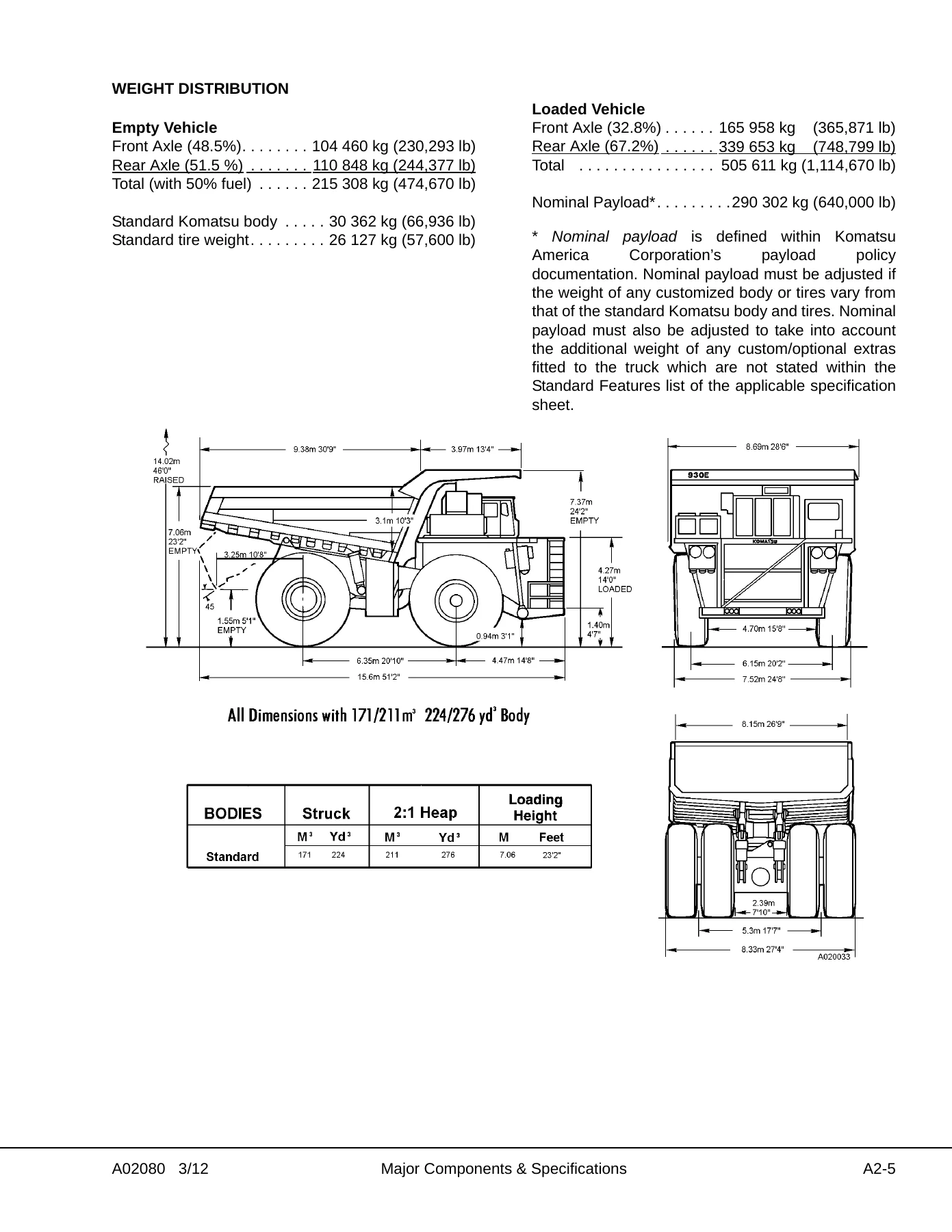
Major component descriptions, full truck and engine specifications, safety and operating instructions, warnings and cautions, standard tightening torque tables for metric and SAE hardware, torque conversion charts, and storage and idle machine preparation procedures. Includes the Komatsu SSDA18V170 engine ratings, AC electric drive system specifications, service capacities, hydraulic system pressures, brake specifications, steering data, tire and rim sizes, dump body capacities, and empty/loaded vehicle weight distribution figures.
Section B – Structures
Diagonal ladder, grille and hood assembly, right-hand deck and retarding grid, left-hand deck, center deck removal and installation. Dump body removal and installation, body pad shimming, body guides, hoist limit switch, body-up switch, body retention sling and rock ejectors. Fuel tank removal, repair, cleaning, installation, vent assembly, fuel gauge sender and quick fill fuel receivers.
Section C – Engine Systems
Power module preparation, removal, installation and hookup using the roll-in/roll-out subframe. Radiator removal, installation, filling, internal inspection, external cleaning, disassembly, assembly and pressure testing. Power train including alternator removal and installation, crankshaft endplay measurement, shim calculation and engine removal. Air cleaners operation, element replacement, cleaning and intake troubleshooting. Fan clutch removal, installation, disassembly, cleaning, inspection, assembly and test procedures.
Section D – Electrical System (24 VDC, Non-Propulsion)
24 VDC electrical supply system, batteries, battery charging alternator, engine start relays, auxiliary battery receptacles, battery disconnect switches, 24 VDC to 12 VDC converter, cranking motor system with prelube, cranking motor troubleshooting, magnetic switch, fuse blocks and circuit breakers, relay boards RB1 through RB9, body-up switch, hoist limit switch, alarm indicating device (AID) system, KOMTRAX Plus, and interface module.
Section E – Electric Propulsion and Control
AC drive system electrical checkout procedure, propulsion system components including Propulsion System Controller (PSC), Truck Control Interface (TCI), Diagnostic Information Display (DID) panel and event codes, alternator field control, propel and retard torque control, wheel slide control, resistor grid control, chopper voltage control, event detection and processing, data packs, serial data communications, and troubleshooting fault codes.
Section G – Drive Axle, Spindles and Wheels
Tires and rims including wheel stud maintenance, front and rear tire and rim removal and installation, rim tire removal and installation. Front wheel hub and spindle removal, spindle removal procedure, installation, disassembly, cleaning and inspection, assembly, wheel bearing adjustment, brake installation, seal assembly gap check and wheel speed sensor testing. Steering cylinders and tie rod service, spherical bearing wear limits, bearing replacement, toe-in adjustment, and tie rod inspection and torque procedure. Rear axle mounting with pivot pin, pivot eye bearing and pivot eye repair. Rear axle and wheel motor including rear axle housing removal, installation and wheel motor service.
Section H – Hydrair II Suspensions
Front and rear suspension removal, installation, inspection, lower bearing and seal service, major suspension rebuild, disassembly, cleaning, inspection, assembly and suspension pressure testing. Suspension oiling and charging procedures with equipment list, Hydrair charging kit, support blocks, front and rear suspension oiling, nitrogen charging, and oil and nitrogen specifications charts.
Section J – Brake Circuit
Service brake circuit, parking brake circuit, brake lock circuit, secondary braking and automatic apply, and warning circuit. Brake circuit component service including brake valve, dual relay valve, brake manifold, brake accumulators, retarder control lever, brake circuit checkout procedure, wet disc brake assembly operation, brake disc wear inspection, brake rebuild, floating ring seal assembly, wet disc brake bleeding procedure and parking brake service.
Section L – Hydraulic System
Hydraulic system overview with pump module, hoist circuit operation, steering circuit operation and disc brake cooling system. Hydraulic system component repair including hoist pump removal, installation, inspection and assembly, hydraulic tank removal, installation, breathers and strainers. Steering circuit, steering control unit, steering circuit component repair, hoist circuit, hoist circuit component repair, hydraulic system filters and hydraulic checkout procedure.
Section M – Options and Special Tools
Hot start system, special tools, radiator shutters, Payload Meter III with operation, calibration, data analysis and troubleshooting, reserve engine oil system, retractable ladder system and camera system.
Section N – Operator’s Cab
Truck cab and components including cab removal and installation, cab door service, door jamb bolt adjustment, door handle plunger adjustment, door glass replacement, door handle or latch assembly, door window regulator, door and hinge seal, glass replacement, windshield and rear glass. Cab components including windshield wipers, wiper motor, wiper arm, wiper linkage, windshield washer, operator seat and passenger seat, seat belt replacement. Heater/air conditioner operation, components, environmental impact, principles of refrigeration, system components, electrical circuit, servicing warnings, service tools, system performance test, system oil, refrigerant, system leak testing, recovery and recycling, system repair, component replacement, evacuating the system, charging the AC system and troubleshooting. Operator cab and controls including steering column, steering wheel, dynamic retarding, grade/speed chart, overhead panel and displays, center console, diagnostic ports, instrument panel, overhead status/warning indicators, rear axle light bar, KOMTRAX Plus and Komatsu Wireless Bridge.
Section P – Lubrication and Service
Lubrication and service general information, service capacities, hydraulic tank service, cooling system service, wheel motor service, reserve engine oil system, quick fill service center, lubrication chart, 10 hour (daily) inspections, 50 hour lubrication and maintenance checks, 100 hour checks, 250 hour checks, 500 hour checks, 1000 hour checks and 5000 hour maintenance checks. Automatic lubrication system general description, system components, operation, lubricant requirements, system priming, filter assembly, lubricant pump, injectors, preventive maintenance procedures, system checkout and system troubleshooting chart.
Section Q – Alphabetical Index
Complete alphabetical index referencing every major subject covered in the shop manual, with cross-references to the relevant section for quick lookup during repairs.
Section R – System Schematics
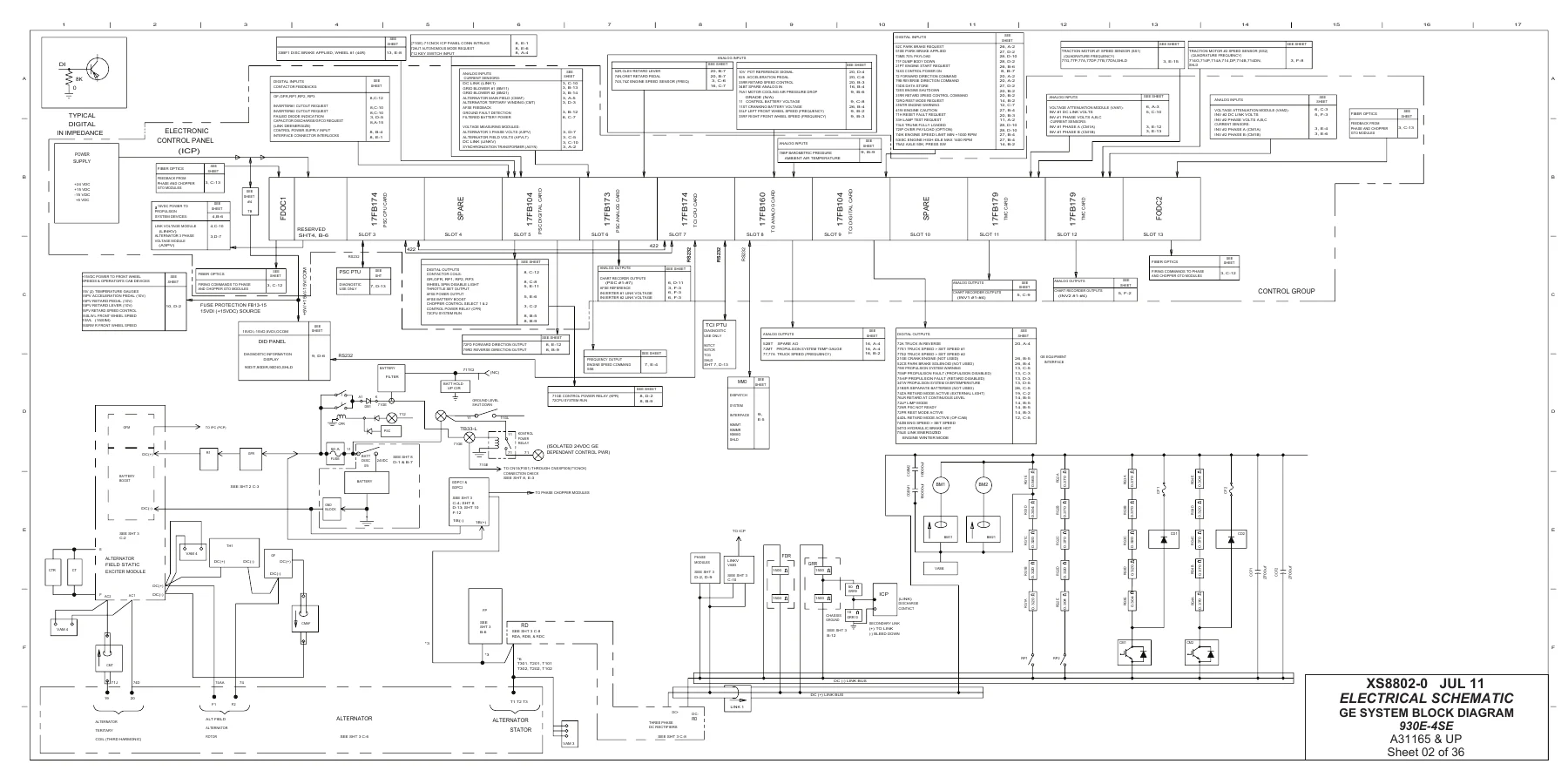
Hydraulic supply, brake cooling, steering and hoist schematic, hydraulic brake system schematic, and full electrical schematics covering 36 sheets: index and symbols, GE system block diagram, main propulsion schematic, 24V/15V power distribution, GE inverter firing, engine I/O, GE/24V digital I/O, control panel analog inputs, 24V power distribution and circuit protection, operator cab overhead warning lights, auto lube system, operator cab gauges and option switches, heater and AC controls, work lights and horn, retard lights, backup lights and horns, operator drive system controls, radio and window controls, clearance lights, fog lights and headlights, operator cab instrument lights, key switch and timed engine shutdown, batteries and engine start circuit, engine circuits, Payload Meter III circuits, diagnostic connectors, MM dispatch system and VHMS/Orbcomm, park brake and GE I/O, windshield wiper and turn signal controls, interface module and RPC/J1939 communication, circuit locator, component locator, hot start and camera system.
What This Komatsu 930E-4SE Shop Manual Lets You Do
With the complete Komatsu 930E-4SE Dump Truck Shop Manual CEBM027101 in hand, you can perform the full range of scheduled and unscheduled maintenance on the truck without guessing. The manual covers the AC electric drive system end to end, including the alternator field control, both inverters, the gate drive power converters, the retarding grid chopper circuits, the traction motorized wheels and the event detection and troubleshooting logic that keeps the truck moving. It also covers the Hydrair II suspensions front and rear, the wet disc service brakes and spring-applied parking brakes, the full hydraulic system from the pump module through the hoist valve and brake cooling circuits, the diesel engine power module, the 24 VDC non-propulsion electrical system, and the operator cab with its heater and air conditioner. You get the torque values, pressure settings, clearances, shim calculations, wheel bearing adjustment procedures, accumulator charging pressures, suspension oiling and nitrogen charging dimensions, and the wiring and hydraulic schematics needed to trace a fault to its source.
Every section in this 930E-4SE shop manual follows the same pattern: component description, removal, installation, disassembly, cleaning and inspection, assembly, testing and troubleshooting. That means whether you are resealing a hoist cylinder, replacing a wet disc brake, setting wheel bearing preload, rebuilding a steering cylinder, charging a suspension accumulator or diagnosing a propulsion system fault code on the DID panel, the procedure is laid out in order with the specifications you need at each step. The 1,366-page Komatsu 930E-4SE service manual is the reference that keeps a 505,611 kg haul truck running safely and productively.
IMAGES PREVIEW
This is a digital PDF download delivered instantly after payment. There is no shipping, no waiting for a physical book, and no risk of a damaged or lost paper copy. The file opens on any device that reads PDFs – desktop, laptop, tablet or phone – and every page can be printed for use in the shop or the field. Whether you need one section on the bench or the whole manual on a rugged laptop in the cab, the format works. Download the Komatsu 930E-4SE Dump Truck Shop Manual CEBM027101 once and keep it for the life of the truck.
Reviews
There are no reviews yet.