
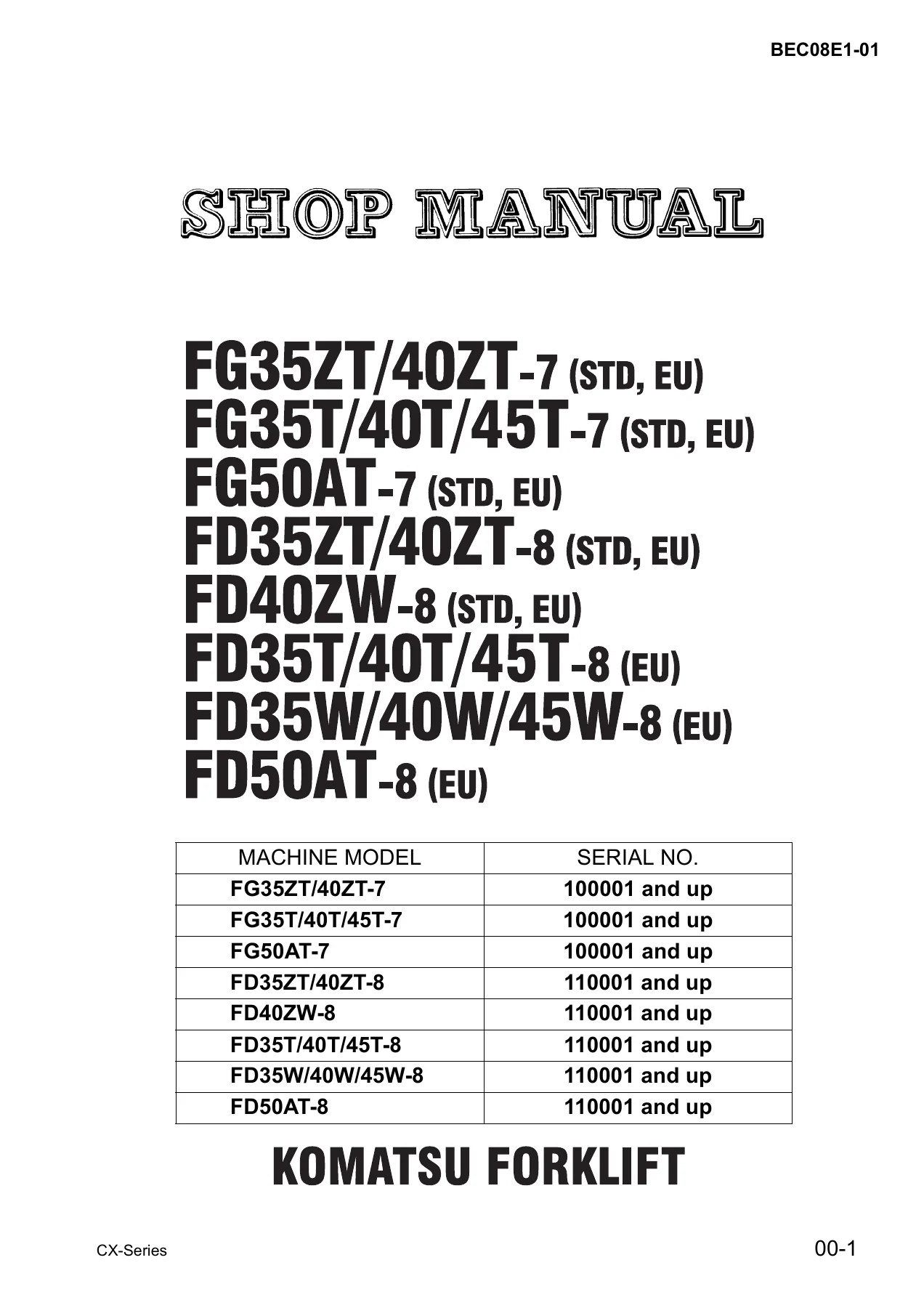
Komatsu CX Series Forklift Shop Manual – FG35ZT to FD50AT-8 Service & Repair PDF (BEC08E1-01)
Original price was: $61.95.$39.95Current price is: $39.95.
Complete Komatsu CX Series forklift shop manual covering FG35ZT/40ZT-7, FG35T/40T/45T-7, FG50AT-7 and FD35ZT/40ZT-8 through FD50AT-8 trucks. 403-page PDF with engine service, TORQFLOW transmission, hydraulics, brakes, steering and troubleshooting for gasoline TB42 and diesel S6D102E machines.
Description
Komatsu CX Series Forklift Shop Manual – Full Workshop Coverage for 3.5 to 5.0 Ton Trucks
This is the complete Komatsu CX Series Forklift Shop Manual (BEC08E1-01), the same factory workshop document used by service technicians working on FG and FD series counterbalance trucks in the 3.5 to 5.0 tonne class. It runs to 403 pages and covers every major assembly on these machines – from the TB42 gasoline and S6D102E diesel engines through the TORQFLOW transmission, drive axle, wheel brakes, power steering and the full hydraulic work equipment circuit. Whether you are servicing a single FG35ZT-7 or running a fleet that spans the entire CX range, this Komatsu CX Series forklift shop manual gives you the specifications, procedures and illustrations needed to do the job correctly.
File Details
- Manual type: Shop / Workshop Service Manual
- Brand: Komatsu Forklift
- Document number: BEC08E1-01
- Models covered: FG35ZT/40ZT-7, FG35T/40T/45T-7, FG50AT-7, FD35ZT/40ZT-8, FD40ZW-8, FD35T/40T/45T-8, FD35W/40W/45W-8, FD50AT-8 (STD and EU specifications)
- Engines covered: NISSAN/TB42 (gasoline), KOMATSU/S6D102E (diesel)
- Language: English
- Page count: 403 pages
- File format: PDF
Chapters Covered
- 00. FOREWORD
- 10. GENERAL AND SPECIFICATIONS
- 20. TESTING AND ADJUSTING
- 30. REMOVAL AND INSTALLATION
- 40. DISASSEMBLY AND ASSEMBLY
- 50. MAINTENANCE STANDARD
- 60. STRUCTURE AND FUNCTION
- 70. TROUBLESHOOTING
- 80. CHECK ITEMS FOR EACH EQUIPMENT
10. General and Specifications
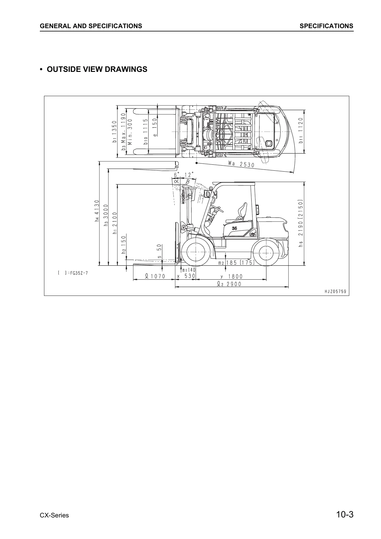
This chapter opens with the safety precautions and symbol conventions used throughout the shop manual, then moves straight into full specification tables for every model in the CX line. Each truck has its own table – the FG35ZT-7 and FD35ZT-8, the FG35T-7/FD35T-7/FD35W-7 group, the FG40ZT-7/FD40ZT-8/FD40ZW-8, the FG40T-7/FD40T-7/FD40W-7, the FG45T-7/FD45T-7/FD45W-7, the FG50AT-7 and FD50AT-7, plus the EU-spec FD35T-8, FD35W-8, FD40T-8, FD40W-8, FD45T-8, FD45W-8 and FD50AT-8. You get rated capacity, load centre, service weight, axle loading, tyre sizes and pressures, mast heights, tilting angles, travel and lift speeds, turning radius, engine output and torque, fuel tank capacity and relief pressure for attachments. Outside view drawings with dimension callouts support each family. The chapter closes with the periodic replacement schedule for consumable parts, safety items for maintenance, the standard tightening torque table, Loctite application procedure and the SI-to-imperial conversion tables.
20. Testing and Adjusting
This is the chapter technicians reach for most often. It opens with a consolidated Service Data table that pulls together the inspection values for the whole machine – idle speed, torque converter stall speed, compression, oil and coolant capacities, injection timing and pressure, valve clearances, TORQFLOW relief pressures, tyre inflation, hub nut torque, brake fluid capacity and lining limits. From there it walks through engine maintenance for both the TB42 and S6D102E – fuel filter, engine oil, oil filter, spark plugs, governor oil, air cleaner element cleaning and replacement, injection timing adjustment (counter mark alignment and dial gauge methods), compression testing and valve clearance setting. It then moves to the accelerator pedal, clutch/brake pedal, inching pedal, wheel brake adjustment, parking brake, TORQFLOW transmission case, differential case, hydraulic tank, hydraulic drift measurement for lift and tilt cylinders, mast synchronous adjustment, finger bar roller setup, radiator cleaning, fuel piping air bleeding, clutch piping, brake piping and lift cylinder bleeding.
30. Removal and Installation
Unit installation positions, the overall disassembly and assembly flowchart, a full weight table by assembly and a set of overall disassembly drawings set the stage. Then the chapter handles the procedures that require lifting gear and care: mast, lift cylinder, engine, clutch or torque converter with transmission and drive axle, steering axle and power steering cylinder, and wheel brake. Each section walks through the removal sequence with the slinging, blocking and pin removal steps spelled out, plus the installation notes and torque values where they matter.
40. Disassembly and Assembly
The largest chapter in the manual. It covers the main clutch, clutch booster and master cylinder, clutch release cylinder, transmission, torque converter, TORQFLOW transmission (including the F1/R1 and F2/R1 input and intermediate shaft sub-assemblies), transmission control valve, differential, wheel brake, brake and clutch boosters, rear axle, steering gear box, combination switch, hydraulic pump, flow divider, control valve, lift cylinder, tilt cylinder, power steering cylinder, mast and fork carriage. For each assembly you get the component parts list, disassembly and assembly drawings with numbered callouts, testing and inspection tables with standard sizes and repair limits, and the reassembly notes – shim selection for the pinion shaft, tooth contact correction, seal ring and cup handling, and the special tool numbers required.
50. Maintenance Standard
A consolidated reference chapter that pulls every check item from the disassembly sections into single tables. Main clutch, transmission, torque converter, TORQFLOW transmission (both F1/R1 and F2/R1), transmission control valve, differential, wheel brake, clutch and brake booster and master cylinder, clutch release cylinder, steering gear box, flow divider, lift cylinder, tilt cylinder, power steering cylinder, mast and fork, fork carriage and steering axle. Each table gives the symbol, the check item, the standard size, the repair limit and the remedy, making it quick to judge whether a part can be reused or must be replaced.
60. Structure and Function
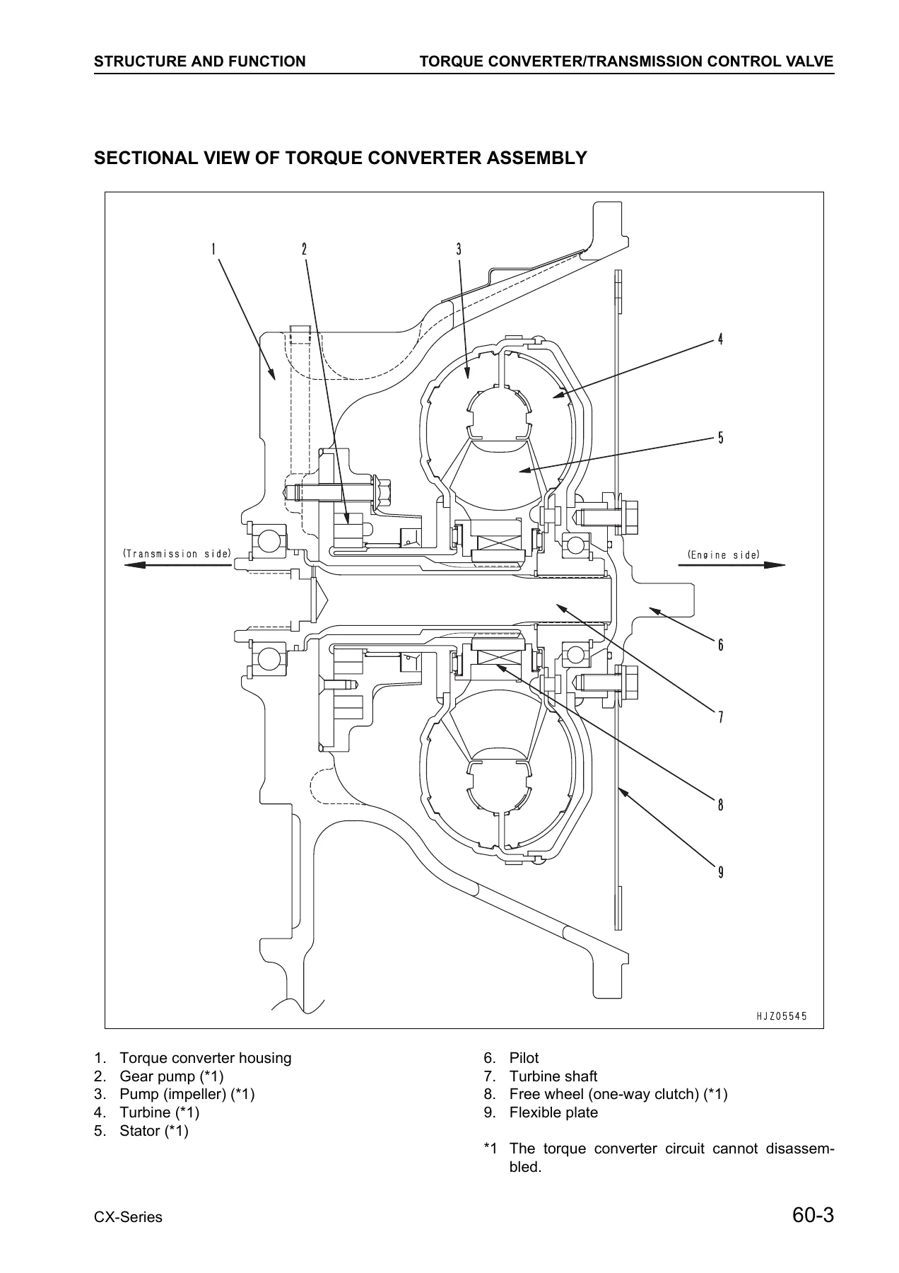
How the machine actually works. This chapter covers the torque converter and transmission control valve, the hydraulic pump, the hydraulic circuit diagram, the flow divider, the control valve (including the load sensing valve and engine stall prevention valve), the brake and clutch booster (flow divider operation and hydraulic booster operation), and the power steering system. Electrical circuit diagrams for both gasoline and diesel engine trucks, including the EU-spec variants, are included, along with a set of assembly drawings covering the TORQFLOW transmission, clutch and transmission, pinion shaft, drive axle, wheel brake, steering axle, frame, piping layouts, control valve, mast and fork carriage.
70. Troubleshooting
A practical fault-finding chapter organised by system. Engine, electrical system, clutch and clutch transmission, TORQFLOW system, steering system, brake system and hydraulic system each get their own problem/cause/remedy tables. The TORQFLOW section is particularly detailed – it separates torque converter and transmission causes for oil temperature rise, noise, lowered horsepower, abnormal oil pressure, power transmission failure and oil leakage, so you can trace a symptom back to the correct component.
80. Check Items for Each Equipment
The periodic inspection chapter. It groups inspection items by component – engine, power train, travel device, steering device, braking device and loading device – and gives the inspection content, the standard value and the adjustment method for each. Starting condition and abnormal sound, idling and acceleration behaviour, exhaust gas colour, air cleaner, valve clearance, compression, governor, lubricating and fuel devices, cooling, electrics, clutch pedal play and pressing effort, clutch transmission, TORQFLOW pressures, directional lever, inching valve, differential, tyres, hub nuts, wheel bearings, steering wheel play, steering gear box, steering linkage, knuckle, rear axle camber and turning radius, power steering pressure, brake pedal, parking brake, brake piping, wheel cylinder, brake drum and shoe, back plate, fork and mast, chain, chain wheel and cylinders.
What This Komatsu CX Series Shop Manual Lets You Do
With this Komatsu CX Series forklift service manual open on your bench or laptop you can carry out a full engine service on the Nissan TB42 or Komatsu S6D102E – set the valve clearances, adjust the injection timing, replace the fuel and oil filters, and test compression. You can pull the TORQFLOW transmission, disassemble the clutch packs, measure the drive and driven plate thickness against the repair limits, reassemble the input and intermediate shaft sub-assemblies and adjust the pinion shaft shim to the correct starting torque. You can service the differential, set the bevel gear backlash and check the tooth contact pattern. You can overhaul the wheel brakes, measure the drum and lining, adjust the automatic adjuster and bleed the brake piping. You can diagnose power steering faults, check the flow divider, test the relief pressures on the hydraulic system and measure the hydraulic drift on the lift and tilt cylinders. And when a fault does appear, the troubleshooting tables let you go straight from symptom to likely cause without guessing.
Why Correct Specifications Matter
Forklifts in this class are worked hard, and a wrong torque value or an out-of-spec clearance can turn a routine repair into a repeat failure. The Komatsu CX Series forklift repair manual gives you the actual values – the cylinder head bolt torque, the pinion shaft starting torque, the clutch plate wear limits, the relief pressures, the backlash figures, the tyre inflation pressures – so you tighten to the correct specification, measure against the correct limit and reassemble in the correct sequence. That is the difference between a truck that goes back to work and a truck that comes back to the workshop.
IMAGES PREVIEW
Instant PDF Delivery
This Komatsu CX Series forklift shop manual is delivered as an instant PDF download – no shipping, no waiting, no physical book to lose. Once payment is complete you can open it on any device: laptop in the workshop, tablet on the machine, or desktop in the office. Every page is printable, so you can pull out the section you need for the job at hand, mark it up and keep it with the truck. Whether you are a single owner-operator looking after one FG35ZT-7 or a fleet workshop supporting FD50AT-8 trucks across multiple sites, this manual puts the full Komatsu CX Series service information in your hands the moment you need it.
Reviews
There are no reviews yet.