
Komatsu D375A-3 Shop Manual SEBM026600 – Complete PDF Service & Repair Guide for S/N 17736 & Up
Original price was: $49.95.$29.95Current price is: $29.95.
Complete Komatsu D375A-3 Shop Manual (SEBM026600) covering structure and function, testing and adjusting, disassembly and assembly, and maintenance standards for machines serial number 17736 and up. 723-page PDF with full troubleshooting sections, hydraulic circuits, wiring diagrams, and technical specifications.
Description
Komatsu D375A-3 Shop Manual – SEBM026600
The Komatsu D375A-3 Shop Manual (document number SEBM026600) is the complete service reference for the D375A-3 crawler dozer from serial number 17736 and up. This shop manual covers the machine’s structure and function, testing and adjusting procedures, disassembly and assembly sequences, and maintenance standards across every major system on the machine – power train, steering and brakes, undercarriage, work equipment hydraulics, and electrical. It is written for the service workshop and the technician who needs accurate specifications, measurement values, and step-by-step teardown and rebuild procedures rather than operator-level information. The engine fitted to the D375A-3 is the SA6D170E-2, and this manual points to the separate 6D170-2 Series Engine Shop Manual for engine-specific details, while still providing engine control and related testing data within its chapters.
File Details
- Manual type: Shop Manual (Service, Repair, Overhaul)
- Brand: Komatsu
- Machine model: D375A-3
- Serial number range: 17736 and up
- Engine reference: SA6D170E-2
- Document number: SEBM026600
- Language: English
- Page count: 723 pages
- File format: PDF
Chapters Covered
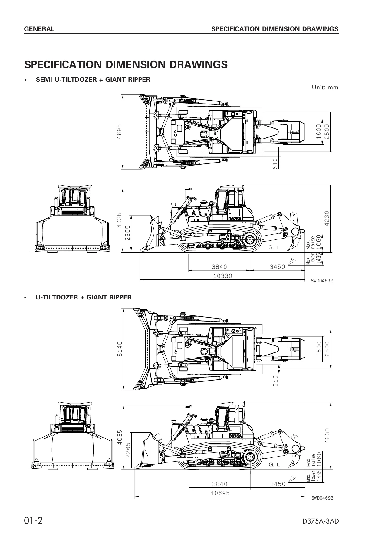
- 01 General – Specification dimension drawings, Specifications, Weight table, Table of fuel/coolant/lubricants
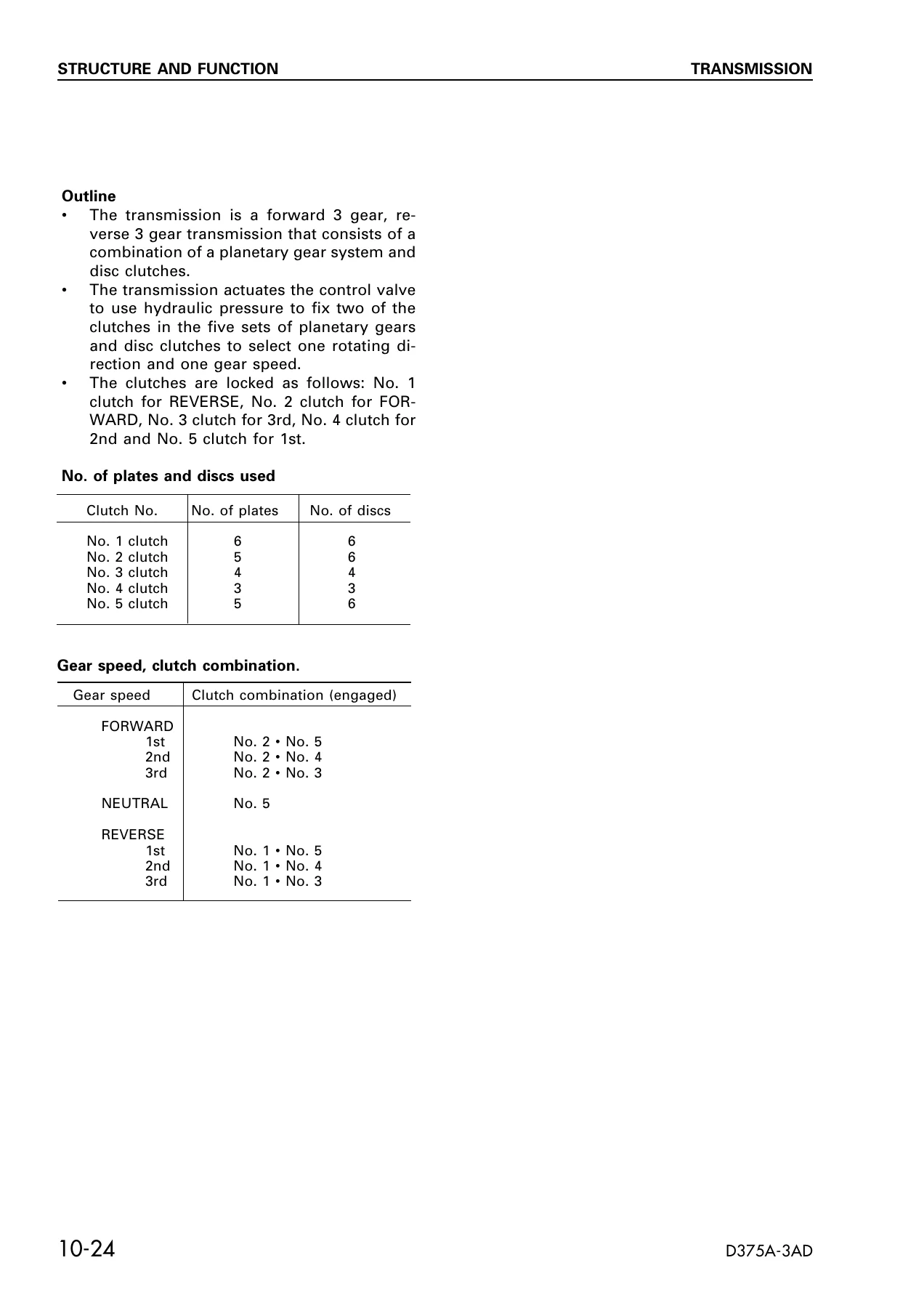
- 10 Structure and Function – Engine control, Power train, Overall power train unit, Torque converter, PTO, Transmission, Transmission control valve, Steering and brake control, Steering control valve, Final drive, Track frame, Recoil spring, Track roller bogie, Main frame, Suspension, Work equipment hydraulic piping and circuits, PPC control, Hydraulic tank, PPC charge valve, Accumulator, PPC lock valve, PPC valve, Piston valve, Quick drop valve, Pin puller, Main control valve, Cylinder stay, Blade, Ripper, Cab, Air conditioner, Monitor system, Switch panel, Fuse box, Engine start safety system, APS
- 20 Testing and Adjusting – Standard value tables (engine, chassis, electrical, monitor), Measuring engine speed, exhaust color, valve clearance, compression pressure, blow-by pressure, engine oil pressure, fuel injection timing, alternator belt tension, air conditioner belt tension, exhaust temperature, air supply pressure, torque converter stall speed, full stall speed, Adjusting fuel control linkage, decelerator pedal, joystick linkage, parking brake lever linkage, brake pedal linkage, work equipment control linkage, Measuring power train oil pressure, work equipment hydraulic pressure, control circuit pressure, PPC valve output pressure, ON-OFF solenoid valve output pressure, Bleeding air, Releasing remaining pressure, Checking hydraulic drift, Measuring cylinder leakage, Adjusting semi U-tiltdozer, idler clearance, brake performance testing, plus full Troubleshooting sections for engine (S mode), hydraulic/mechanical (H mode), machine monitor (M mode), and electrical (E mode)
- 30 Disassembly and Assembly – Starting motor, Alternator, Engine oil cooler, Fuel injection pump, Water pump, Thermostat, Turbocharger, Aftercooler core, Nozzle holder, Engine front seal, Engine rear seal, Cylinder head, Fuel tank, Radiator, Radiator guard, Engine, Damper, Power train unit, PTO, Torque converter, Torqflow transmission, Steering case, Power train lubrication pump, Scavenging pump, Torque converter oil cooler, Torque converter valve, Transmission control valve, Transmission lubrication valve, Steering control valve, Final drive, Track frame, Idler, Recoil spring, Track roller, Bogie, Carrier roller, Track shoe, One link, Master link, Pivot shaft, Equalizer bar, Equalizer bar bushing, Segment tooth, Hydraulic tank, Work equipment PPC pump, Blade lift valve, Blade tilt/ripper Lo valve, Ripper Hi valve, PPC charge valve, Blade PPC valve, Ripper PPC valve, Blade lift cylinder, Blade tilt cylinder, Ripper lift cylinder, Ripper tilt cylinder, Hydraulic cylinder, Ripper pin-puller, Blade, Giant ripper, ROPS guard, Operator’s cab, Floor frame, Dashboard, Monitor panel, APS controller, Air conditioner compressor, Air conditioner condenser, Hood
- 40 Maintenance Standard – Engine mount, Damper and universal joint, Torque converter, Torque converter valve, Transmission, Transmission control valve, Power train lubrication pump, Scavenging pump, Transfer and bevel pinion, Bevel gear shaft, Steering clutch, Brake, Steering control valve, Final drive, Main frame, Track frame, Recoil spring, Idler, Track roller bogie, Track roller, Carrier roller, Track shoe, Single shoe, Equalizer bar, Pivot shaft, Work equipment PPC charge pump, Work equipment control valve, PPC valve, PPC charge valve, Work equipment cylinder, Quick drop valve, Cylinder stay, Blade, Ripper equipment
- 90 Others – Electrical circuit diagram
What This Komatsu D375A-3 Shop Manual Covers
The Komatsu D375A-3 Shop Manual SEBM026600 is organised around the way a service workshop actually works through a machine. The General chapter opens with specification dimension drawings, machine specifications, a component weight table for transport and handling, and the fuel, coolant, and lubricant table. Structure and Function then walks through every major system on the D375A-3, explaining how the power train, torque converter, transmission, steering clutches and brakes, final drive, undercarriage, work equipment hydraulics, and monitor system are built and how they operate. Hydraulic circuit drawings and power train layouts are included to give a clear picture of oil flow and component interaction.
Testing and Adjusting is where the Komatsu D375A-3 shop manual becomes a working tool. Standard value tables give measurement conditions, standard values, and permissible limits for engine, chassis, electrical, and monitor items. Procedures cover engine speed, exhaust color, valve clearance, compression pressure, blow-by, engine oil pressure, fuel injection timing, belt tensions, exhaust temperature, boost pressure, torque converter stall speed, full stall speed, and the adjustment of the fuel control linkage, decelerator pedal, joystick and parking brake linkage, brake pedal linkage, and work equipment control linkage. Power train oil pressure, work equipment hydraulic pressure, control circuit pressure, PPC valve output pressure, and ON-OFF solenoid valve output pressure all have their own measurement procedures. The manual also covers bleeding air from hydraulic cylinders, releasing remaining pressure, checking the location of hydraulic drift, measuring cylinder leakage, adjusting the semi U-tiltdozer, adjusting idler clearance, and a simple procedure for testing brake performance.
Troubleshooting is broken into four modes. S mode handles the engine – starting performance, engine not starting, poor pickup, engine stopping during operation, hunting, lack of output, black exhaust smoke, excessive oil consumption, contaminated oil, excessive fuel consumption, oil in cooling water, oil pressure caution lamp, rising oil level, overheating, abnormal noise, and vibration. H mode covers hydraulic and mechanical systems – machine lacks power, machine does not move in different speed ranges, travels only in one direction, excessive time lag when shifting, machine does not turn or turns only one way, turns too far, brakes do not work, power train oil overheats, all work equipment speeds slow, work equipment does not move, individual blade and ripper functions slow or lacking power, excessive hydraulic drift of blade lift, blade tilt, and ripper, pin-puller cylinder not working, blade pitch not working, and abnormal noise from around the hydraulic pump. M mode covers the machine monitor system – no display, lamps staying lit, caution items flashing, preheating abnormality, buzzer, warning lamp, gauges, service meter, and monitor panel lighting. E mode covers the electrical system – engine does not start, defective APS operation, back-up alarm, lamps, pin-puller cylinder, blade dual tilt, and blade pitch.
Disassembly and Assembly provides the removal, installation, disassembly, and assembly procedures for every major component on the D375A-3. This includes the starting motor, alternator, engine oil cooler, fuel injection pump, water pump, thermostat, turbocharger, aftercooler core, nozzle holder, engine front and rear seals, cylinder head, fuel tank, radiator, radiator guard, engine, damper, power train unit, PTO, torque converter, Torqflow transmission, steering case, power train lubrication pump, scavenging pump, torque converter oil cooler and valve, transmission control and lubrication valves, steering control valve, final drive, track frame, idler, recoil spring, track roller, bogie, carrier roller, track shoe, one link, master link, pivot shaft, equalizer bar, equalizer bar bushing, segment tooth, hydraulic tank, work equipment PPC pump, blade lift valve, blade tilt and ripper Lo valve, ripper Hi valve, PPC charge valve, blade PPC valve, ripper PPC valve, blade lift cylinder, blade tilt cylinder, ripper lift cylinder, ripper tilt cylinder, hydraulic cylinder, ripper pin-puller, blade, giant ripper, ROPS guard, operator’s cab, floor frame, dashboard, monitor panel, APS controller, air conditioner compressor, air conditioner condenser, and hood. Each procedure includes tightening torques, special tool references, coating and sealing instructions, and assembly precautions.
Maintenance Standard provides the judgement criteria for inspection of disassembled parts across every major assembly. This includes wear limits, clearances, interference values, press-fitting forces, spring free lengths and installed loads, and repair limits for the engine mount, damper and universal joint, torque converter and its valve, transmission and control valve, power train lubrication pump, scavenging pump, transfer and bevel pinion, bevel gear shaft, steering clutch, brake, steering control valve, final drive, main frame, track frame, recoil spring, idler, track roller bogie, track roller, carrier roller, track shoe, single shoe, equalizer bar, pivot shaft, work equipment PPC charge pump, work equipment control valve, PPC valve, PPC charge valve, work equipment cylinder, quick drop valve, cylinder stay, blade, and ripper equipment. The Others chapter contains the electrical circuit diagram.
Who This D375A-3 Shop Manual Is For
This is a workshop-level reference for the mechanic, technician, or shop that services the Komatsu D375A-3 crawler dozer. It is not an operator’s manual and does not cover operating techniques or daily checks in the way a machine manual would. The procedures assume access to a service workshop, lifting equipment, special tools, and measuring instruments. The testing and adjusting sections reference specific Komatsu tooling and give measurement conditions such as oil temperatures of 45-55 degrees C, power train oil temperatures of 70-90 degrees C, and engine speeds at low and high idling. The disassembly and assembly sections reference special tool part numbers and list component weights in kilograms, so the technician can plan lifting and handling safely. If you are rebuilding a D375A-3 power train, diagnosing a steering complaint, setting up the blade or ripper hydraulics, or chasing an electrical fault in the monitor system, this manual gives you the sequence, the values, and the limits.
Why the Komatsu D375A-3 Shop Manual Matters
Correct procedures and correct specifications are the difference between a repair that lasts and one that comes back. The Komatsu D375A-3 Shop Manual gives the technician the measurement conditions under which values should be taken, the standard and permissible values themselves, and the assembly torques and clearances that keep the machine within specification. The troubleshooting flowcharts narrow down causes systematically instead of by guesswork, and the disassembly and assembly procedures reduce the risk of damage to seals, bearings, and machined surfaces. For a machine of this size and complexity, working without the shop manual means working blind – the manual is the reference that keeps the job accurate and repeatable.
IMAGES PREVIEW
Instant PDF Delivery
The Komatsu D375A-3 Shop Manual SEBM026600 is delivered as an instant PDF download after payment. There is no shipping, no waiting for a physical book, and no risk of a lost parcel. The file can be opened on any device that reads PDFs – desktop, laptop, tablet, or phone – and can be printed if a paper copy is preferred in the workshop. Keep it on a shop computer, load it onto a tablet for use at the machine, or print the sections you need for the job at hand. This Komatsu D375A-3 shop manual gives you the complete service reference for the D375A-3 in a single file, ready to use the moment you download it.

Reviews
There are no reviews yet.