
Komatsu D475A-2 Bulldozer Shop Manual – PDF Service, Testing & Repair Guide
Original price was: $74.95.$49.95Current price is: $49.95.
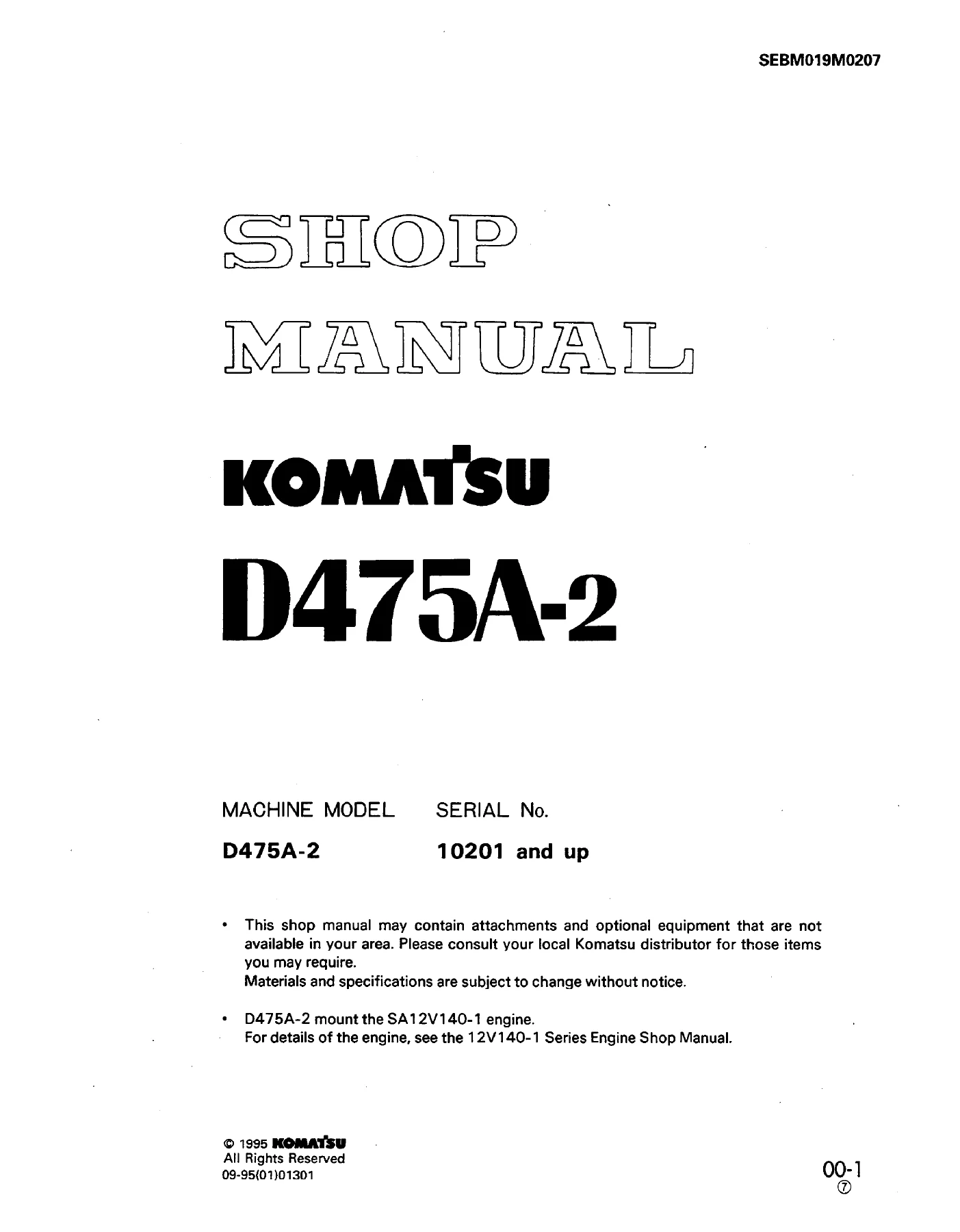
Komatsu D475A-2 Bulldozer Shop Manual PDF for machines from serial 10201 and up. Covers structure and function, testing and adjusting, disassembly and assembly, and maintenance standards.
Description
Komatsu D475A-2 Bulldozer Shop Manual – PDF Service, Testing & Repair Guide
This Komatsu D475A-2 Bulldozer Shop Manual is a 621-page PDF service and repair guide for the D475A-2 bulldozer, covering machines from serial number 10201 and up. It is organized around the four core workshop sections used by technicians: structure and function, testing and adjusting, disassembly and assembly, and maintenance standards. The manual applies to the D475A-2 model, which the PDF notes mounts the SA12V140-1 engine. Engine overhaul details are not included in this chassis shop manual; the first page directs readers to the separate 12V140-1 Series Engine Shop Manual for engine-specific information. That makes this PDF especially useful for chassis, power train, hydraulic, undercarriage, electrical, and work equipment work on the D475A-2.
File Details
- Manual type: Shop Manual
- Document title: SHOP MANUAL KOMATSU D475A-2
- Brand/model: Komatsu D475A-2
- Engine reference: SA12V140-1
- Serial No.: 10201 and up
- Language: English
- Page count: 621 PDF pages
- File format: PDF
Chapters Covered
- 10 STRUCTURE AND FUNCTION
- 20 TESTING AND ADJUSTING
- 30 DISASSEMBLY AND ASSEMBLY
- 40 MAINTENANCE STANDARD
10 STRUCTURE AND FUNCTION
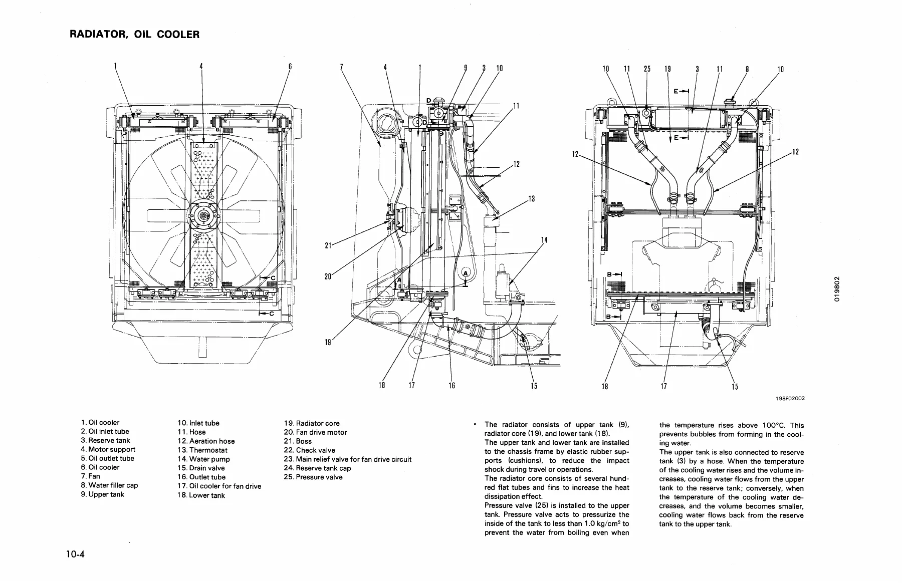
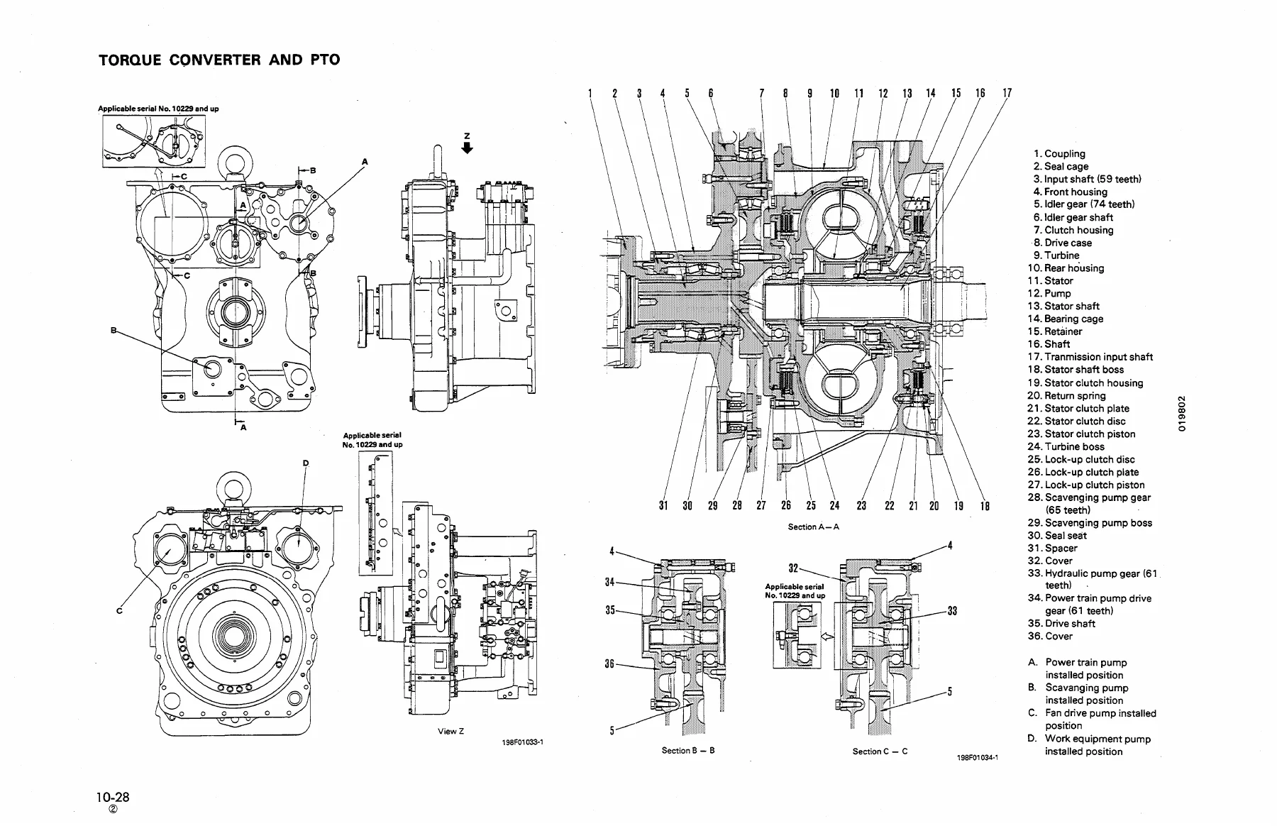
The structure and function chapter explains how the major D475A-2 systems are built and how they operate. It covers the engine mount, radiator and oil cooler, fan drive hydraulic piping, fan drive hydraulic system and circuit, fan drive pump and motor, fan high-low speed selector solenoid valve, check valve, fan drive circuit main relief valve, in-line servo valve, and engine control. The power train section covers the power train layout, power train unit, piping, hydraulic system and circuit, damper and universal joint, torque converter and PTO, torque converter valve, transmission, scavenging pump, power train pump and lubrication pump, strainers, oil filters, transfer, bevel pinion, bevel gear shaft, steering clutch, steering brake, steering control valve, final drive, and power train unit mount. The undercarriage section describes the lubricated track link, track frame, recoil spring, idler, track roller, carrier roller, and suspension. The hydraulic system section covers the hydraulic piping diagram, hydraulic control, circuit system and diagram, hydraulic tank, hydraulic pump, blade lift valve, main relief and shuttle valve, blade tilt and ripper low valve, ripper high valve, hydraulic lever operation, cylinder, ripper cylinder, and pin-puller hydraulic system and solenoid valve. The work equipment section covers dozer equipment, ripper equipment, and cylinder stay. The electric and electronic system section includes the electrical wiring diagram, cab wiring diagram, air conditioner circuit diagram, EVMS, electrical control, sensors, and pin-puller control. Other sections cover the ROPS canopy, cab, and air conditioner.
20 TESTING AND ADJUSTING
The testing and adjusting chapter provides the checks, measurements, and adjustments needed before and after repairs. It begins with standard value tables for the engine, chassis, and electrical judgement values, then moves into specific procedures such as adjusting valve clearance, measuring compression pressure, checking and adjusting fuel injection timing, measuring torque converter stall speed, bleeding air from hydraulic cylinders, measuring oil pressure, and adjusting the fuel control linkage, gear shift lever linkage, steering clutch linkage, brake pedal linkage, blade control linkage, and ripper control linkage. This section also contains troubleshooting charts that relate problems to causes, including troubleshooting for hydraulic and mechanical systems, electrical systems, and the monitor system. For a D475A-2 owner or technician, this is the chapter that supports diagnosis rather than guesswork: it gives the pressure pickup points, linkage dimensions, stall-speed procedure, oil pressure measurement steps, and adjustment sequences needed to bring the machine back to specification.
30 DISASSEMBLY AND ASSEMBLY
The disassembly and assembly chapter is the hands-on removal and installation guide for major D475A-2 components. It opens with the method of using the manual, precautions for operation, piping precautions during disassembly, a special tool list, weight table, lubricant and coolant table, and tightening torques and standard values. It then covers removal and installation of the starting motor, alternator, engine oil cooler, torque converter cooler, fuel injection pump, water pump, turbocharger, aftercooler core, nozzle holder, cylinder head, fuel tank, radiator, radiator guard, fan drive pump, fan motor, engine, damper, power train unit, PTO and torque converter, TORQFLOW transmission, steering case, steering clutch and brake, transfer gear housing, final drive, track shoe, equalizer bar, idler yoke cartridge pin, idler pad, hydraulic pump, blade lift valve, blade tilt and ripper Lo valve, ripper Hi valve, blade lift cylinder, blade tilt cylinder, ripper lift cylinder, ripper tilt cylinder, pin puller cylinder, work equipment, ripper, and ROPS cab. It also includes disassembly and assembly procedures for the torque converter, PTO, TORQFLOW transmission, steering case, steering clutch and brake, transfer gear, final drive, track shoe, and hydraulic valves and cylinders. Component weights are listed where the manual provides them, which is useful when planning lifting equipment and shop space.
40 MAINTENANCE STANDARD
The maintenance standard chapter gives the judgement criteria used when inspecting disassembled parts. It covers engine mount clearances and rubber mount height, fan drive pump and motor clearances, in-line servo valve checks, damper dimensions, torque converter and torque converter valve clearances and spring data, TORQFLOW transmission clutch disc and plate thicknesses, transmission control valve clearances and spring lengths, power train lubrication pump clearances, transfer and bevel pinion backlash, bevel gear and steering clutch and brake dimensions, steering control valve clearances, final drive backlash and bearing clearances, main frame bushing and pin clearances, track frame deformation limits, recoil spring free and installed lengths, idler and track roller wear limits, carrier roller limits, track link pitch and bushing wear, equalizer bar interference and clearances, pivot shaft clearances, work equipment pump clearances, blade lift valve spring data, main relief and shuttle valve spring data, blade tilt and ripper low valve spring data, ripper high valve spring data, hydraulic cylinder clearances, cylinder stay clearances, dozer equipment pin and bushing clearances, cutting edge and end bit wear limits, and ripper equipment pin, bushing, point, and protector wear limits. These are the values a shop needs when deciding whether a part can be reused, repaired, or replaced.
What This D475A-2 Shop Manual Supports in the Workshop
This Komatsu D475A-2 shop manual PDF is aimed at the jobs that keep a large bulldozer productive: tracing a hydraulic fault through the fan drive or work equipment circuit, checking transmission and steering clutch pressures, adjusting control linkages after repair, removing and installing the power train unit, rebuilding a steering clutch and brake assembly, setting final drive backlash, or inspecting undercarriage wear against maintenance standards. Because the manual separates structure and function from testing and adjusting, and then from disassembly and assembly, it supports both diagnosis and repair. A technician can read how a system works, check it against standard values, then follow the removal and assembly sequence without mixing chapters. The maintenance standard chapter is particularly useful when a machine is already apart and the question is not how to remove a part but whether it is still within serviceable limits.
Practical Details for the D475A-2
The PDF identifies the D475A-2 as the machine model and gives a serial number range of 10201 and up. It lists the SA12V140-1 engine and notes that engine details are found in the 12V140-1 Series Engine Shop Manual. The shop manual itself covers the chassis and machine systems, including the power train, undercarriage, hydraulic system, work equipment, and electrical and electronic systems. It includes wiring diagrams, hydraulic circuit diagrams, component cross-sections, exploded views, tightening torque tables, weight tables, lubricant and coolant capacities, special tool lists, and troubleshooting flow charts. For anyone maintaining or repairing a D475A-2, this is the type of reference that keeps procedures, pressures, clearances, and torque values in one place instead of scattered across notes or generic guides.
Get the Komatsu D475A-2 Bulldozer Shop Manual as an Instant PDF
This Komatsu D475A-2 Bulldozer Shop Manual gives you a practical, chapter-by-chapter service reference for structure and function, testing and adjusting, disassembly and assembly, and maintenance standards. It supports real workshop decisions: which pressure to check, which linkage dimension to set, which components to remove in what order, which parts to inspect against wear limits, and which torque values to apply. The PDF is delivered instantly after payment, with no shipping and no waiting for a physical book. You can open it on a laptop, tablet, or phone, print the pages you need for the job, and keep the complete manual available for future repairs. Whether you are servicing the hydraulic system, pulling the power train, rebuilding the steering clutches and brakes, or checking undercarriage wear, this D475A-2 shop manual is a direct, searchable-by-eye workshop companion for the machine.
IMAGES PREVIEW
Reviews
There are no reviews yet.