
Komatsu D475A-5EO D475ASD-5EO Bulldozer Shop Manual PDF (Serial 30001 & Up)
Original price was: $39.95.$23.95Current price is: $23.95.
Complete Komatsu shop manual for the D475A-5EO and D475ASD-5EO bulldozer, serial numbers 30001 and up. 388 pages of specifications, structure and function, maintenance standards, hydraulic and electrical circuit diagrams, work equipment and undercarriage service data.
Description
Komatsu D475A-5EO / D475ASD-5EO Shop Manual – File Details
- Manual type: Shop Manual (workshop service manual, multi-booklet set)
- Brand / manufacturer: Komatsu
- Machines covered: D475A-5EO and D475ASD-5EO Bulldozer
- Serial numbers: D475A-5EO 30001 and up; D475ASD-5EO 30001 and up
- Document form numbers: SEN00203-00 through SEN00226-00
- Language: English
- File format: PDF
- Page count: 388 pages
- Publisher: Komatsu America Corp. – Copyright 2006
Chapters Covered in the Komatsu D475A-5EO / D475ASD-5EO Bulldozer Shop Manual
- 00 Index and foreword – organization list of the shop manual, foreword and general information, safety notice, how to read the shop manual, explanation of terms for maintenance standard, handling electric equipment and hydraulic components, how to read electric wire codes, push-pull type coupler disassembly and connection, standard tightening torque table, conversion tables
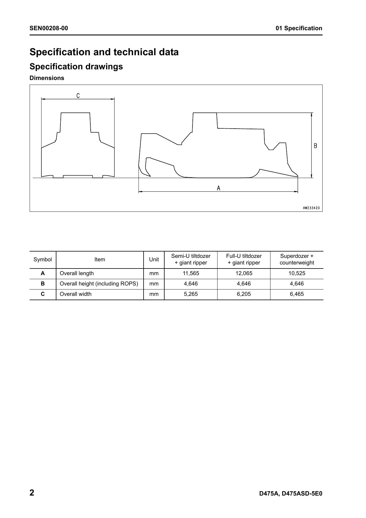
- 01 Specification – specification drawings, specifications, weight table, fuel, coolant and lubricants
- 10 Structure, function and maintenance standard – Engine and cooling system – radiator and oil cooler, engine mount, cooling fan pump, cooling fan motor
- Power train, Part 1 – power train hydraulic equipment arrangement, damper and universal joint, power train system, general view of power train unit, torque converter and PTO, torque converter valve, torque converter lockup control system, scavenging pump, transmission control, transmission
- Power train, Part 2 – transmission control valve, transmission clutch ECMV, priority valve, lubricating oil relief valve, torque converter and power train lubricating oil pump, steering and brake control, final drive
- Undercarriage and frame – track frame, recoil spring, idler, track roller, carrier roller, track roller bogie, track shoe, main frame, suspension
- Hydraulic system, Part 1 – work equipment hydraulic equipment arrangement diagram, PPC control piping diagram, work equipment control, work equipment pump, PPC valve, PCCS lever
- Hydraulic system, Part 2 – control valve, CLSS, unload valve, introduction of LS pressure, LS bypass plug, pressure compensation valve, blade lift valve, merge-divider valve, self pressure reducing valve, pilot solenoid valve
- Hydraulic system, Part 3 – hydraulic tank and hydraulic filter, accumulator, work equipment cylinder, piston valve, quick drop valve, blade control knob (dual tilt specification), blade control knob (superdozer specification), pitch and dual solenoid valve, pin puller hydraulic circuit diagram, pin puller solenoid valve
- Work equipment – cylinder stay, blade, ripper equipment
- Cab and its attachments – cab mount, cab, air conditioner
- Electrical system – engine control, engine control system, deceleration potentiometer, CRI engine control system, monitor system, monitor panel, sensors, mode selection system, electrical equipment, steering electronic control system, VHMS controller, communication (ORB) controller and antenna
- 90 Diagrams and drawings – power train hydraulic circuit diagram, hydraulic circuit diagram (1/3, 2/3, 3/3), electrical circuit diagram (1/13 through 13/13), electrical circuit diagram of inside cab
This Komatsu D475A-5EO D475ASD-5EO bulldozer shop manual is built as a multi-booklet service set, and the PDF delivered here gathers that set into one continuous document. The structure follows the way Komatsu arranged the original material: general information and safety first, then the machine specification section, then the largest block of the manual covering structure, function and maintenance standard for every major assembly, and finally the hydraulic and electrical diagram section. That last section is where the practical work usually starts, because the power train hydraulic circuit diagram and the thirteen-sheet electrical circuit diagram let you trace oil flow and current path from the pump or battery all the way to the actuator, sensor or solenoid without guessing.
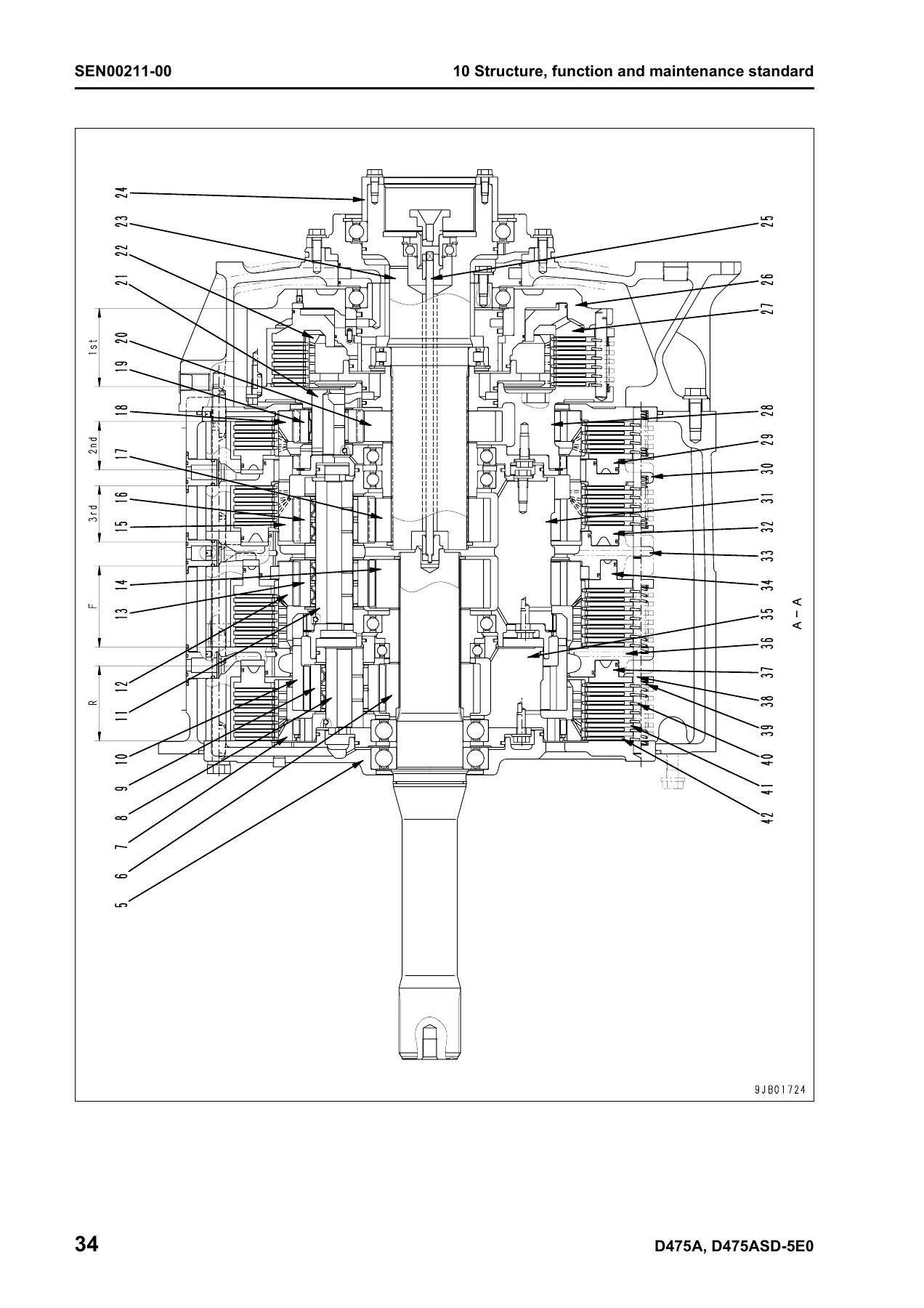
Inside the structure and function chapters, each assembly is presented the same way: an outline of what the component does, an explanation of how it works, exploded and cutaway illustrations with numbered parts, and a maintenance standard table giving standard size, tolerance, standard clearance and clearance limit, plus the remedy when the limit is passed. The transmission, steering clutch and brake, final drive, torque converter, track roller, idler, recoil spring, suspension and work equipment cylinders all get this treatment, which is what makes the manual usable for a rebuild rather than just a teardown.
What This Komatsu Bulldozer Service Manual Supports
The D475A-5EO and D475ASD-5EO are large, heavily loaded machines, and the manual reflects that. The engine chapter covers the Komatsu SAA12V140E-3 powerplant as installed, along with its cooling package – main radiator, sub radiator, oil cooler, water pump, cooling fan pump and cooling fan motor. Because the fan drive on these machines is hydraulic and electronically controlled, the shop manual walks through the LPV90 + LPV30 variable swash plate fan pump, its PC valve, EPC valve and servo piston, and the LMF180 fixed swash plate fan motor with its safety-suction valve and forward/reverse selector circuit. That is the kind of detail you do not find in a generic service book.
The power train chapters go from the damper and universal joint through the three-element, single-stage, single-phase torque converter with lockup clutch, into the planetary transmission with its forward and reverse clutches and three speed clutches, then out through the transfer, bevel gear shaft, steering clutch and brake, and final drive. The torque converter valve, lockup solenoid valve, lockup selector valve, stator clutch modulating valve and lockup clutch modulating valve are all broken out with operation descriptions, so diagnosing a lockup that will not engage or a stator clutch that will not release becomes a matter of following the described oil path rather than trial and error.
Steering and braking on these dozers is electronically managed through the PCCS lever, steering controller, steering clutch ECMV and steering brake ECMV, with a parking brake valve and a sudden stop prevention valve in the circuit. The electrical system chapter covers the monitor panel, monitor system processing, sensors, mode selection, VHMS controller pinouts, communication controller and antenna, and the steering electronic control system – a full picture of how the machine’s electronics talk to each other.
Why the D475A-5EO / D475ASD-5EO Shop Manual Matters
Clearances and torque values on a machine this size are not forgiving. The maintenance standard tables in this shop manual give the numbers a workshop actually needs – for example, the clearance limits for the track roller shaft and bushing, the brake plate and disc thickness limits, the bevel pinion to bevel gear backlash range, and the clutch disc and plate assembly thicknesses for the R, F, 1st, 2nd and 3rd clutches. Using the correct figure the first time avoids pulling a final drive or a steering unit twice.
The diagram section is equally practical. The power train hydraulic circuit diagram and the multi-sheet hydraulic circuit diagrams show how the work equipment pump, control valve, merge-divider valve, pressure compensation valves, quick drop valves and blade lift cylinders are plumbed, while the thirteen electrical circuit sheets and the inside-cab diagram let you trace a fault through the harness rather than replacing parts on suspicion. The foreword also includes guidance on handling wiring harnesses and connectors, drying a water-contaminated connector, handling controllers, and keeping hydraulic circuits clean – all of which matter when you are working on an electronically controlled machine in the field.
Whether the job is a routine filter and oil service, a hydraulic pump reseal, a transmission clutch overhaul, a steering brake rebuild, a track frame and recoil spring service, or electrical fault-finding on the monitor and mode selection system, this Komatsu D475A-5EO D475ASD-5EO bulldozer shop manual is the reference that keeps the work inside the manufacturer’s specification.
IMAGES PREVIEW
Instant PDF Delivery
The manual is supplied as a PDF download. There is no shipping and no waiting – the file is available immediately after checkout and can be opened on a workshop laptop, a tablet on the machine, or a phone, and any page or diagram can be printed for use at the bench. Keep the full 388-page set on hand and work through the D475A-5EO or D475ASD-5EO with the same information a Komatsu service workshop would use.
Reviews
There are no reviews yet.