
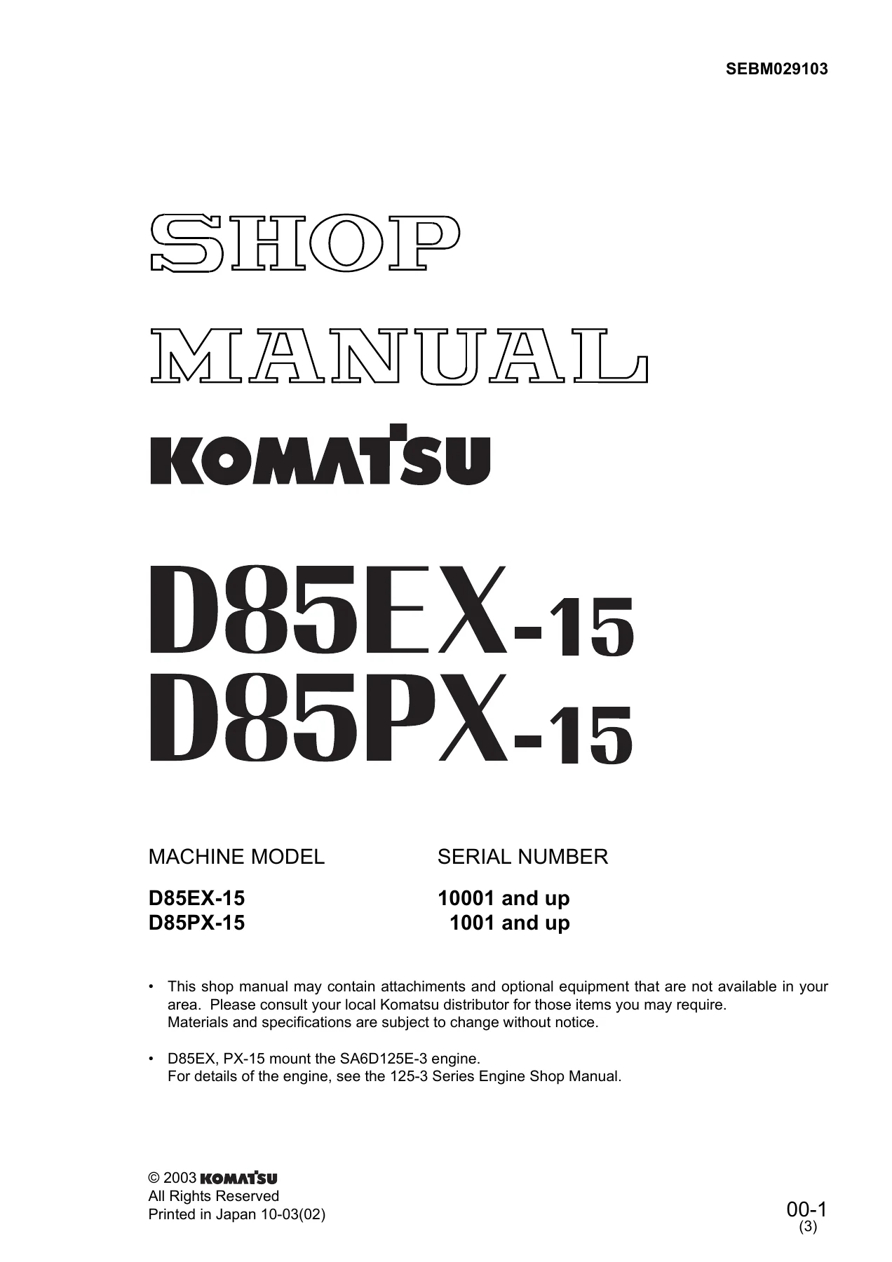
Komatsu D85EX-15 D85PX-15 Dozer Shop Manual SEBM029103 – Full PDF Repair Guide
Original price was: $39.95.$23.95Current price is: $23.95.
Complete Komatsu shop manual for the D85EX-15 and D85PX-15 dozers (serial 10001-up / 1001-up). Covers structure, function, testing, adjusting, disassembly, assembly, hydraulic and electrical circuit diagrams. Instant PDF download of document SEBM029103.
Description
Komatsu D85EX-15 D85PX-15 Shop Manual – Document SEBM029103
This is the complete Komatsu shop manual for the D85EX-15 and D85PX-15 dozers, published under document number SEBM029103. It is the workshop reference Komatsu service personnel use when diagnosing, testing, adjusting, disassembling and rebuilding these crawler dozers, and it applies to D85EX-15 serial number 10001 and up and D85PX-15 serial number 1001 and up. The manual is written for the SA6D125E-3 engine, with engine internals covered in the companion 125-3 Series Engine Shop Manual.
File Details
- Manual type: Komatsu Shop Manual (service, testing, adjusting, disassembly and assembly)
- Brand: Komatsu
- Models covered: D85EX-15, D85PX-15
- Serial numbers: D85EX-15 – 10001 and up; D85PX-15 – 1001 and up
- Engine referenced: SA6D125E-3
- Document number: SEBM029103
- Language: English
- Format: PDF (instant download, printable, viewable on any device)
- Coverage structure: 01 General / 10 Structure, Function and Maintenance Standard / 20 Testing and Adjusting / 30 Disassembly and Assembly / 90 Others
Chapters Covered
- 01 General – Specification drawing, Specifications, Weight Table, Table of fuel, coolant and lubricant
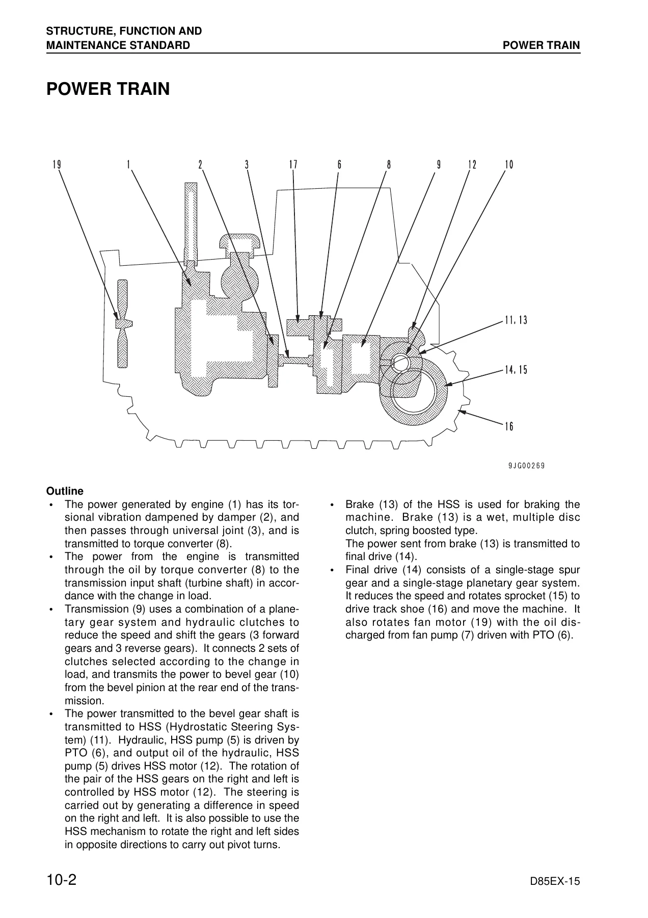
- 10 Structure, Function and Maintenance Standard – Power train overall, Damper and universal joint, Torque converter and PTO, Scavenging pump, Transmission control, Transmission, Transmission ECMV, Main relief valve, Lubrication relief valve, Power train pump, HSS system, Hydraulic HSS pump, HSS motor, HSS oil cooler bypass valve, Steering and brake control, Bevel gear shaft, Brake valve, Final drive, Sprocket, Track frame, Recoil spring, Idler, Track roller, Carrier roller, Track shoe, Main frame, Suspension, Work equipment hydraulic piping, PPC control, Cooling fan pump and motor, Hydraulic tank, Accumulator, PPC lock valve, Hydraulic cylinder, Piston valve, Quick drop valve, PPC valve, PCCS lever, Control valve, Self pressure reducing valve, Cylinder stay, Blade, Ripper, Cab mount, Cab, Air conditioner, Engine control, CRI engine control system, Monitor system, Monitor panel, Sensors, Palm Command Control System
- 20 Testing and Adjusting – Standard value tables for engine and chassis, Tools for testing/adjusting/troubleshooting, Measuring engine speed, Measuring intake air pressure (boost), Measuring exhaust temperature and gas color, Adjusting valve clearance, Measuring compression pressure, Measuring blow-by pressure, Measuring engine oil pressure, Handling of fuel system devices, Releasing residual pressure from fuel system, Measuring fuel pressure, Bleeding air from fuel circuit, Reduced cylinder mode operation, Alternator and air conditioner belt tension, Adjusting fuel control dial and decelerator pedal, Measuring power train oil pressure, Adjusting transmission speed sensor, Brake performance testing, Adjusting brake pedal, Emergency escape method when power train has trouble, Adjusting idler clearance, Inspecting wear of sprocket, Track shoe tension, Work equipment and HSS oil pressure, Control circuit main pressure, PPC valve output pressure, Work equipment PPC valve play, Hydraulic drift testing, Measuring internal leakage of work equipment cylinder, Bleeding air from cylinders, Adjusting safety lock lever, Measuring fan motor speed and fan pump circuit pressure, Adjusting blade, Operator’s cab testing, Special functions of monitor panel (EMMS), Handling of high-voltage circuit of engine controller, Adjustment method of replaced controller, Pm clinic service, Undercarriage troubleshooting report
- 30 Disassembly and Assembly – Fuel supply pump, Fuel injector, Nozzle tip, Engine front seal, Engine rear seal, Engine cylinder head, Engine oil pan, Fuel tank, Radiator, Engine, Damper, Power train unit, Torqflow transmission, HSS, PTO, Torque converter, Scavenging pump, HSS and work equipment pump, Fan pump, Power train and lubricating oil pump, HSS motor, Final drive, Track frame, Idler, Recoil spring, Track roller, Carrier roller, Track shoe, Pivot shaft, Equalizer bar, Work equipment control valve, Hydraulic cylinder, Blade, Ripper, ROPS guard, Operator’s cab, Operator’s cab glass (stuck glass), Floor frame, Engine controller, Steering and transmission controller, Engine hood, Fan drive, Fan motor
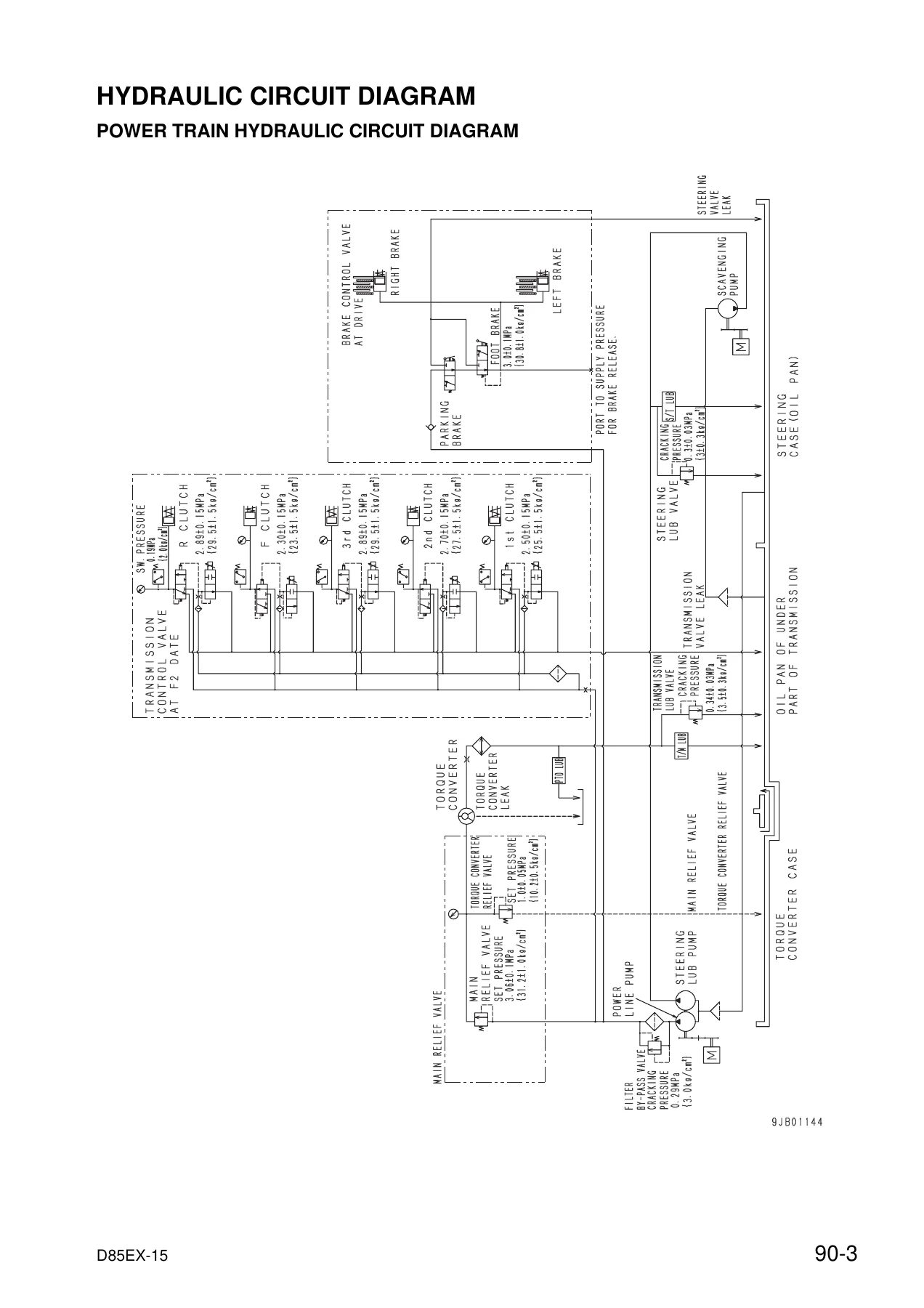
- 90 Others – Power train hydraulic circuit diagram, Work equipment hydraulic circuit diagrams (fixed multiple shank ripper, variable multiple shank ripper, general), Electrical circuit diagrams (6 sheets), Cab electrical circuit diagram
Coverage is deep enough that a technician can take the machine from a routine pressure check all the way to a full transmission or final drive rebuild. The structure and function chapter explains how the torque converter, Torqflow planetary transmission, HSS hydrostatic steering system, bevel gear shaft, spring-applied brake, final drive and the closed-center load-sensing work equipment control valve actually behave, then the testing and adjusting chapter gives the standard values, service limits, adjustment screw procedures and monitor panel EMMS service functions needed to prove the fault. From there, the disassembly and assembly chapter walks through the order of work for every major assembly, including the tightening torques, shim and preload adjustments, seal handling and the special tools Komatsu recommends. The 90 section closes the loop with the hydraulic and electrical circuit diagrams a technician needs to trace a fault through the machine rather than guess at it.
The chapters are cross-referenced, so a symptom found during testing can be chased straight into the component-level disassembly procedure and back to the specifications table without leaving the document. Serial number ranges are stated up front, and the tables call out the differences between the D85EX-15 and D85PX-15 where they matter.
What This Komatsu D85EX-15 D85PX-15 Shop Manual Enables You To Do
With the Komatsu D85EX-15 D85PX-15 shop manual on hand, an owner or workshop technician can perform the full spread of scheduled maintenance and repair jobs on these dozers: set valve clearance, measure compression and blow-by, bleed the CRI fuel circuit, test the torque converter and transmission clutch pressures, adjust the brake pedal and parking brake linkage, correct track shoe tension, measure work equipment and HSS relief pressures, and interpret the monitor panel’s EMMS service mode codes to find faults that would otherwise require a dealer visit.
On the repair side, the same manual supports the harder jobs – removing the Torqflow transmission, splitting the power train unit, rebuilding the HSS unit and bevel gear shaft, replacing final drive bearings and floating seals, rebuilding blade lift, blade tilt and ripper cylinders, removing the operator’s cab, and replacing the stuck cab glass – using the exact sequences, press forces, shim selection tables and torque values Komatsu specifies.
Getting these procedures right matters. Komatsu’s gear train, hydraulic and electrical systems on the D85EX-15 and D85PX-15 are heavily interdependent, and tightening a bearing without the correct preload, mixing up shims, or skipping the air-bleed steps after a hydraulic repair can turn a straightforward job into a repeat failure. A workshop manual written for the exact serial range removes that risk and keeps the machine running to specification.
IMAGES PREVIEW
The manual is delivered as an instant PDF download after payment – no shipping, no waiting. It can be read on a laptop, tablet or phone in the workshop, printed page by page for the job at hand, or kept as an archive copy for the whole life of the machine.

Reviews
There are no reviews yet.