
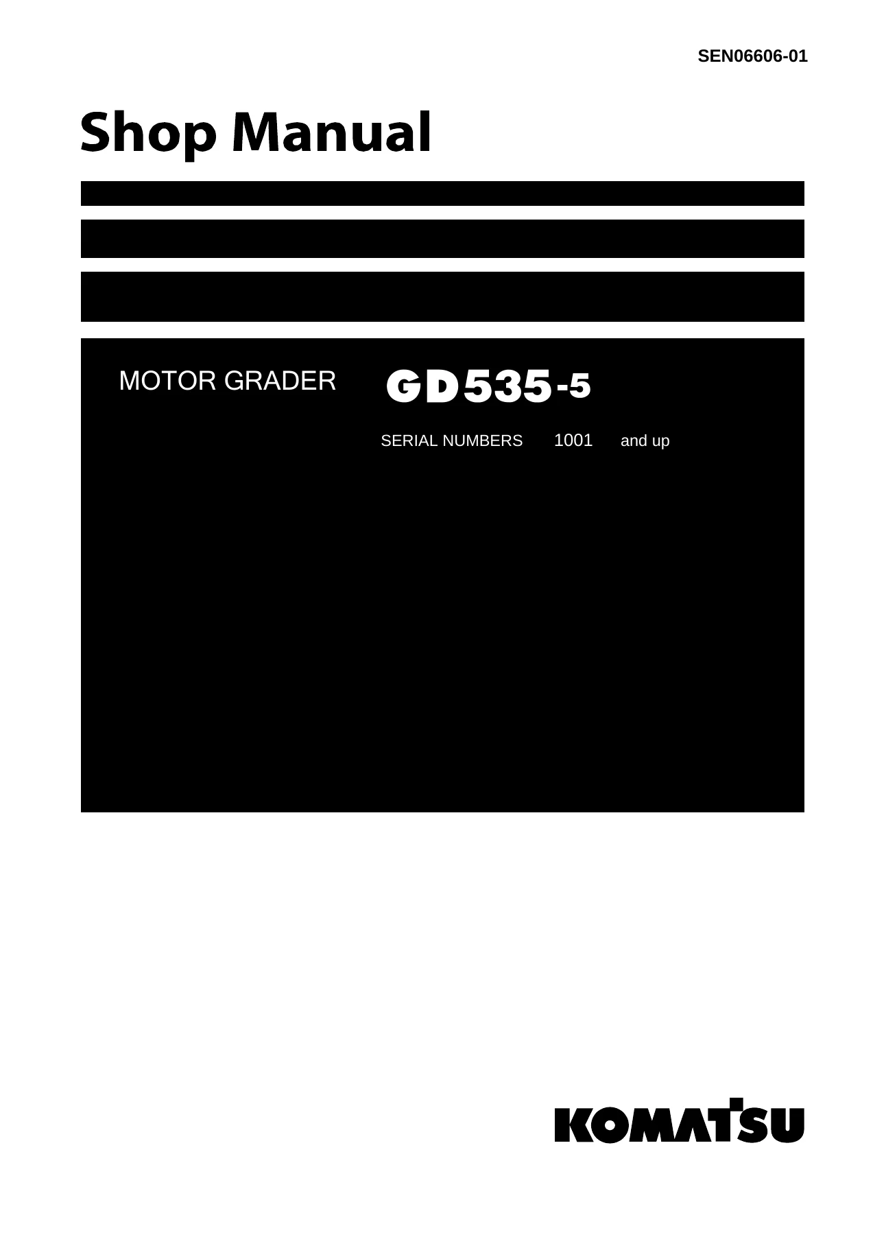
Komatsu GD535-5 Motor Grader Shop Manual SEN06606-01 PDF
Original price was: $39.95.$24.95Current price is: $24.95.
Complete Komatsu GD535-5 Motor Grader Shop Manual (SEN06606-01) for serial numbers 1001 and up. 1,310 pages covering specifications, structure and function, testing and adjusting, troubleshooting, disassembly and assembly, maintenance standards, and hydraulic/electrical diagrams. Instant PDF download.
Description
Komatsu GD535-5 Motor Grader Shop Manual – Complete Service & Repair Reference
This Komatsu GD535-5 Motor Grader Shop Manual is the complete workshop reference for machines with serial numbers 1001 and up. Published under document number SEN06606-01 (1st revision, September 2016), it spans 1,310 pages covering specifications, structure, testing, troubleshooting, disassembly, maintenance standards, and diagrams for the GD535-5. Every section is written for the technician working on the machine, not for the operator looking for a quick answer.
File Details
- Manual type: Shop Manual (workshop service and repair)
- Brand: Komatsu
- Model: GD535-5 Motor Grader
- Serial numbers: 1001 and up
- Engine: Komatsu SAA6D107E-1 diesel
- Document number: SEN06606-01
- Revision: 1st revision
- Publication date: September 2016
- Language: English
- Page count: 1,310
- File format: PDF
Chapters Covered
The Komatsu GD535-5 shop manual is organized into ten top-level sections. Each is built for a different stage of the repair process, from understanding what the machine is meant to do through tearing it down and putting it back together to the correct clearances and torques.
- 00 Index and foreword — Acronyms, foreword and general information, safety notice, how to read the shop manual, explanation of terms for maintenance standard, handling of electric equipment and hydraulic components, handling of connectors newly used for engines, how to read electric wire code, precautions when carrying out work, disassembly and connection of push-pull type couplers, standard tightening torque table, conversion table.
- 01 Specification — Acronyms, specifications, specification drawing, weight table, table of fuel, coolant, and lubricants.
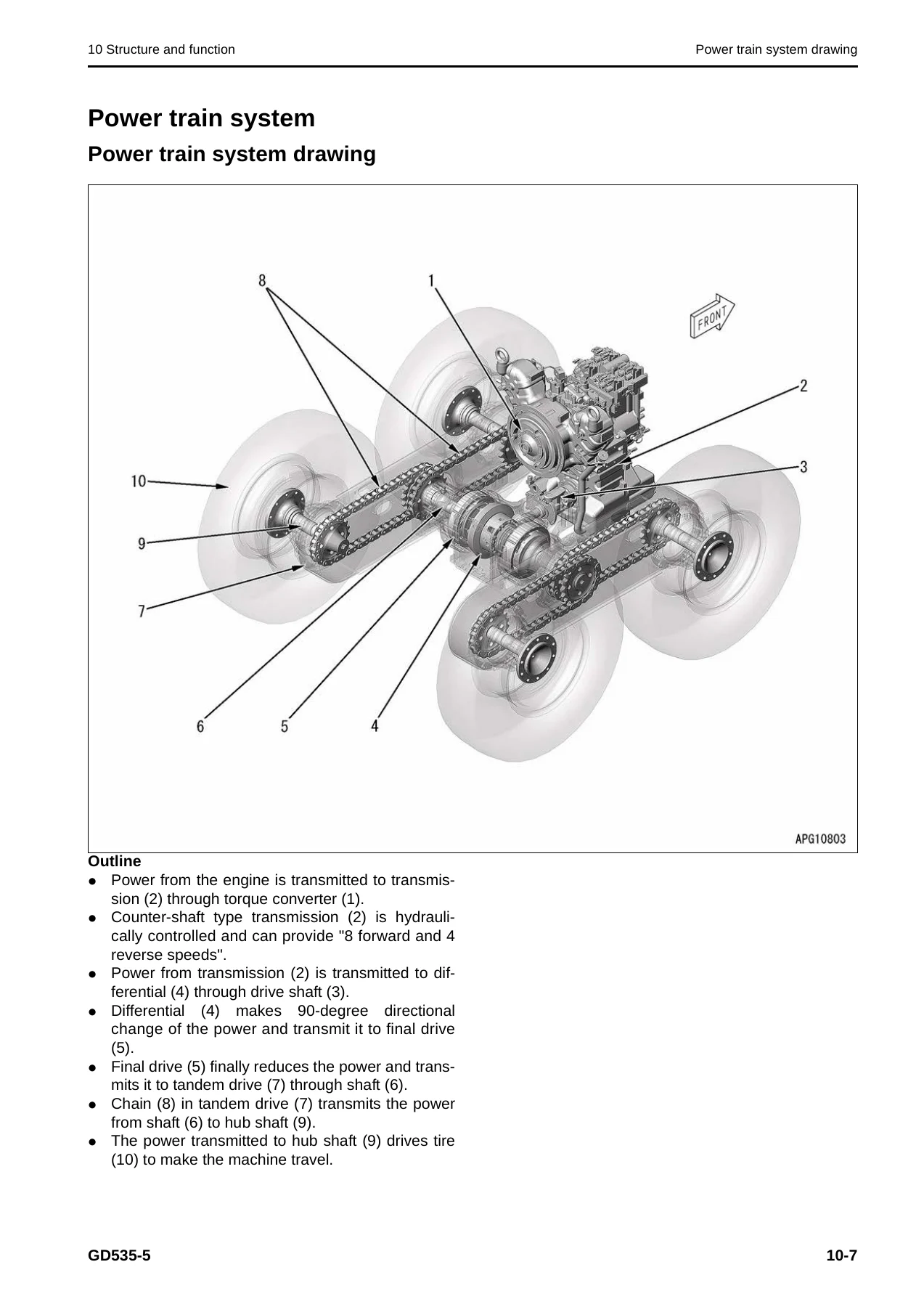
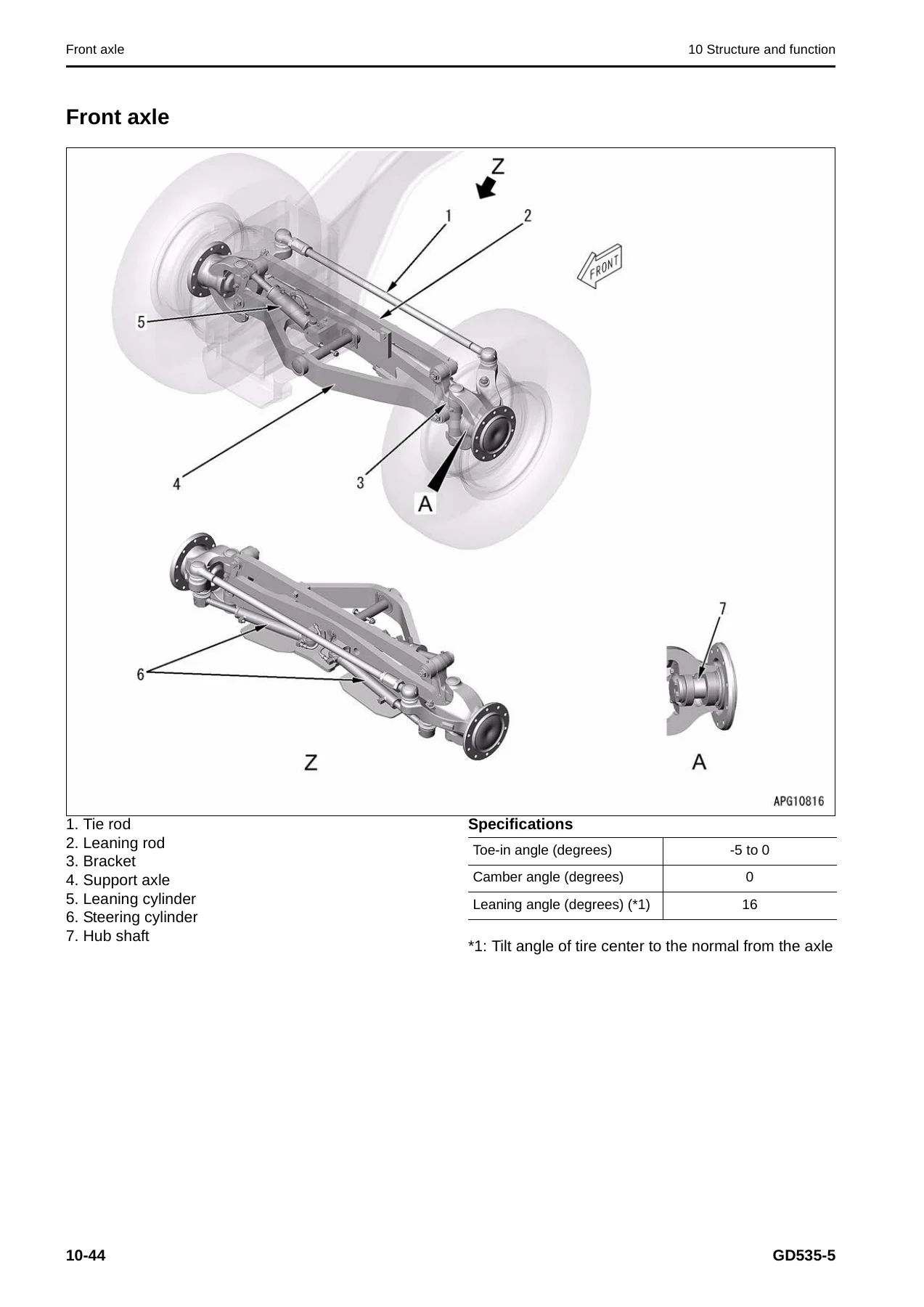
- 10 Structure and function — Engine and cooling system, cooling system, fan drive; power train system, power train system drawing, power train piping drawing, transmission control, torque converter, transmission, transmission control valve, ECMV, main relief valve and torque converter relief valve; front axle, rear axle, differential (non-differential and differential lock specifications), differential lock solenoid valve, final drive, tandem drive; steering system, steering piping drawing, priority valve, steering valve; brake system, hydraulic piping drawing of brake system, brake valve, brake circuit accumulator, brake circuit accumulator charge valve, wheel brake, parking brake solenoid valve and lifter lock pin solenoid valve, parking brake; frame, tire; hydraulic system, hydraulic piping drawing of work equipment, work equipment control, hydraulic tank, work equipment pump and steering pump, power train pump, power train pump and differential lock pump, brake pump, control valve, functions and valve operations, hydraulic cylinder, swivel joint, pilot check valve; work equipment system, circle and drawbar, blade, lifter, circle rotation motor, circle rotation gear; canopy and related parts, ROPS canopy; electrical system, machine monitor, automatic gear shift control system, transmission controller, engine controller, KOMTRAX system, KOMTRAX terminal, engine starting circuit, engine stop circuit, preheating circuit, sensors, engine power mode selector circuit.
- 20 Standard value table — Acronyms, standard value table for engine, standard value table for machine.
- 30 Testing and adjusting — Tools for testing, adjusting, and troubleshooting; engine and cooling system (testing engine speed, boost pressure, exhaust gas temperature, exhaust gas color, adjusting valve clearance, compression pressure, blowby pressure, engine oil pressure, handling fuel system devices, releasing remaining pressure, testing fuel pressure, bleeding air from fuel circuit, testing fuel circuit for leakage, cylinder cutout mode, no-injection cranking, voltage circuit of engine controller, muffler testing, installed condition of cylinder heads and manifolds, engine piping, fuel discharge and return rate, replacing fan belt); power train (testing power train oil pressure, adjusting transmission speed sensor, retrieval of disabled machine due to transmission valve failure, flushing procedure, toe-in, differential lock oil pressure); steering system (steering oil pressure, oil leakage, bleeding air); brake system (releasing remaining pressure, brake oil pressure, bleeding air, wheel brake disc wear, parking brake pad, manual release, charging brake accumulator with gas); hydraulic system (work equipment oil pressure, lifter lock pin circuit pressure, oil leakage of work equipment cylinder, bleeding air); work equipment (drawbar ball joint clearance, circle guide clearance, slip clutch type circle drive); electrical system (testing diodes, special functions of machine monitor, high-voltage circuit, KOMTRAX terminal start-up, preparatory work for troubleshooting); Pm Clinic.
- 40 Troubleshooting — Acronyms, information related to troubleshooting, points to remember, how to proceed, checks before troubleshooting, inspection procedure, troubleshooting procedure, failure code list, symptoms and troubleshooting numbers, information described in troubleshooting table, diagnosis of open harness in pressure sensor system, connector list and layout, connector pin layout, T-box and T-adapter list, locations of fuses; troubleshooting by failure code (engine and transmission failure codes); electrical system (E-mode) with E-1 to E-28; hydraulic and mechanical system (H-mode) with H-1 to H-27; engine (S-mode) with S-1 to S-16.
- 50 Disassembly and assembly — Acronyms, related information, how to read, coating materials list, special tool list, sketches of special tools; engine and cooling system (supply pump, injector, cylinder head, alternator belt, engine front and rear oil seals, radiator, aftercooler, power train oil cooler, fuel tank, engine hood); power train (engine, transmission and torque converter assembly, torque converter, transmission, tandem drive and final drive); steering system (Orbitrol valve); brake system (wheel brake); undercarriage and frame (center hinge pin); hydraulic system (hydraulic tank, battery and frame, control valve, hydraulic cylinders); work equipment (blade, circle drawbar, circle rotation gear); canopy and attachments; electrical system (engine controller, machine monitor, transmission controller, KOMTRAX terminal).
- 60 Maintenance standard — Acronyms, engine mount and transmission mount, cooling system, torque converter, transmission, main relief valve and torque converter relief valve, front axle, rear axle, differential (non-differential and differential lock specifications), final drive, differential lock solenoid valve, tandem drive, steering cylinder, wheel brake, parking brake, frame and center hinge pin, hydraulic tank, work equipment pump and steering pump, power train pump, power train pump and differential lock pump, parking brake solenoid valve and lifter lock pin solenoid valve, leaning cylinder, articulate cylinder, blade lift cylinder, drawbar shift cylinder, blade side shift cylinder, power tilt cylinder, scarifier cylinder, circle and drawbar, blade, lifter, circle rotation gear.
- 90 Diagrams and drawings — Acronyms, symbols used in hydraulic circuit diagrams, hydraulic circuit diagram, power train hydraulic circuit diagram, symbols used in electric circuit diagrams, chassis electric circuit diagram, floor electric circuit diagram.
That’s the complete architecture of the GD535-5 shop manual: ten sections that cover every system on the machine from the SAA6D107E-1 engine and its cooling package through the power train, steering, brakes, hydraulics, work equipment, and the electrical/electronic control layer that ties them together. The specification and standard value tables give the technician the numbers; the structure and function chapters explain how each assembly works; testing and adjusting tells you how to verify and correct it; troubleshooting locates faults by failure code, symptom, or system; disassembly and assembly walks through the physical work; and maintenance standard gives the wear limits and repair criteria that determine whether a part is reusable or must be replaced. The diagrams section provides both hydraulic and electrical circuit drawings for the complete machine.
What This Manual Covers in Practice
The GD535-5 is a Komatsu motor grader powered by the SAA6D107E-1 diesel engine, a 6-cylinder unit with 107 mm bore and 124 mm stroke (6.69 L displacement). The manual covers both the E mode and P mode engine ratings, the 8-forward/4-reverse countershaft transmission, the torque converter with lockup clutch, the rear axle differential (both non-differential and differential lock variants), tandem drive, front axle with hydraulic leaning, full hydraulic power steering, wet multiple-disc service brakes, and the open-center work equipment hydraulic system with its 9-spool control valve.
Every major procedure in the GD535-5 shop manual is documented with the special tools required, the tightening torques, the coating materials, and the measurement points. Whether you’re adjusting valve clearance, testing boost pressure, retrieving a disabled machine after a transmission valve failure, flushing the torque converter and transmission circuits, testing the differential lock oil pressure, bleeding the brake circuit, adjusting the parking brake pad, or disassembling the transmission assembly — the procedure and its acceptance criteria are in this manual.
The troubleshooting section is particularly extensive. Failure codes are listed with their action level and history category, and each code has a dedicated troubleshooting table with causes, measurement locations, criteria, and remedies. The electrical system troubleshooting (E-mode) covers everything from engine does not start to KOMTRAX system does not operate normally. The hydraulic and mechanical system troubleshooting (H-mode) uses a matrix approach to isolate problems in the power train, steering, brakes, and work equipment. The engine troubleshooting (S-mode) covers startability, power loss, exhaust smoke, oil consumption, overheating, and abnormal noise or vibration.
Why This Manual Matters
Motor grader repair without the correct specifications is guesswork. The GD535-5 has specific clearances, preloads, backlash values, oil pressures, and electrical signal ranges that determine whether the machine will operate correctly after a repair. The maintenance standard chapter gives the standard dimensions, tolerances, repair limits, and allowable clearances for every major component. The standard value table provides the engine and machine performance data — speeds, pressures, temperatures, travel speeds, work equipment speeds, hydraulic drift limits — with both the standard value for a new machine and the repair limit.
For a machine with serial numbers 1001 and up, this manual is the reference that matches the specific build. It covers the optional differential lock, the power tilt mechanism, and the scarifier where equipped, and it distinguishes between configurations where the procedure or specification differs.
IMAGES PREVIEW
Instant PDF Delivery
The Komatsu GD535-5 Motor Grader Shop Manual is delivered as an instant PDF download after purchase. No shipping, no waiting. The file works on any device — desktop, laptop, tablet, or phone — and every page is printable for use in the workshop. Keep it on a shop computer, print the sections you need for a specific job, or reference it from a tablet at the machine. The 1,310-page document is fully navigable and organized by section so you can go straight to the system you are working on.
Whether you are maintaining a single GD535-5 or running a fleet, this manual gives you the complete Komatsu service information for the machine in one file — the same technical depth that a workshop needs to diagnose, repair, and verify the motor grader correctly.
Reviews
There are no reviews yet.