
Komatsu GD555-5 GD655-5 GD675-5 Motor Grader Shop Manual SEN05215-04
Original price was: $79.95.$54.95Current price is: $54.95.
Complete 1468-page shop manual for Komatsu GD555-5, GD655-5 and GD675-5 motor graders from serial number 55001 and up. Covers specifications, structure and function, standard values, testing and adjustment, troubleshooting, component removal and installation, disassembly and assembly, maintenance standards, air conditioning, and hydraulic/electrical diagrams.
Description
Komatsu GD555-5 GD655-5 GD675-5 Motor Grader Shop Manual SEN05215-04
This 1468-page Komatsu GD555-5 GD655-5 GD675-5 Motor Grader Shop Manual SEN05215-04 provides the technical information used for workshop service of the three covered grader models. Coverage applies to GD555-5 55001 and up, GD655-5 55001 and up, and GD675-5 55001 and up. It brings together machine specifications, system construction and operation, service standards, testing procedures, fault diagnosis, removal and installation work, component disassembly and assembly, maintenance limits, air-conditioning information, and circuit drawings in one extensive reference.
The manual is especially useful when a repair requires more than a basic parts view or maintenance checklist. It explains how major systems operate before moving into measurements, adjustment procedures, diagnostic logic and mechanical service work. The specification section identifies the Komatsu SAA6D107E-1 diesel engine used across the covered models and provides machine dimensions, performance data, hydraulic information, work-equipment dimensions, component weights, and fluid capacities.
File Details
- Manual type: Shop Manual
- Equipment: Motor Grader
- Models: GD555-5, GD655-5, GD675-5
- Serial coverage: GD555-5 55001 and up; GD655-5 55001 and up; GD675-5 55001 and up
- Document number: SEN05215-04
- Revision: 4th revision, 2010/11
- Language: English
- Pages: 1468
- File format: PDF
Machine and Service Information Inside
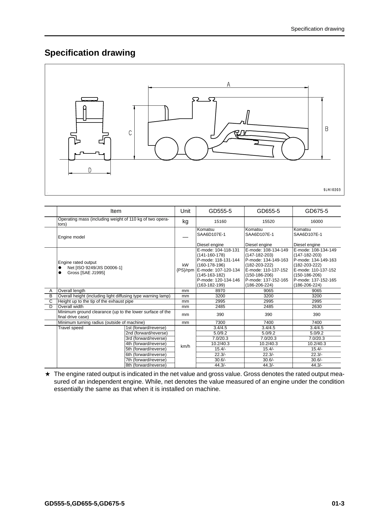
The specification material establishes the differences and common service data for the three graders. It includes operating and machine mass figures, axle loads, travel speeds, drawbar pull, gradeability, turning radius, overall dimensions and wheelbase information. Engine data covers the SAA6D107E-1 engine, its 4-cycle water-cooled direct-injection turbocharged and air-aftercooled configuration, cylinder bore and stroke, displacement, rated output, torque, idle speeds, starting motor, alternator and battery information.
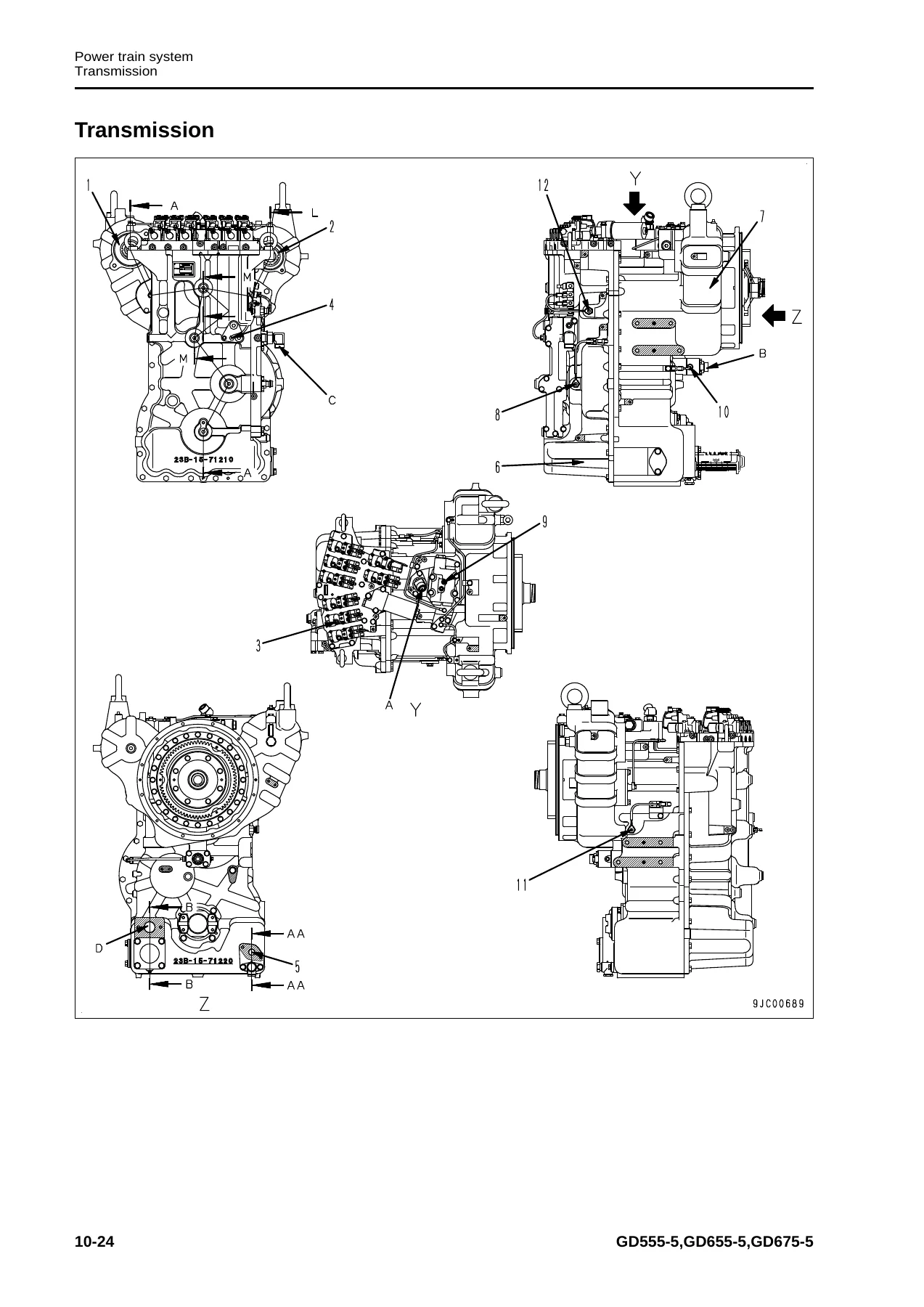
Power-train information describes the torque converter, electronically controlled counter-shaft transmission, final reduction gear, tandem drive and axle arrangements. The transmission is covered as an 8-speed-forward and 4-speed-reverse unit, with detailed clutch layouts, power-transmission routes, control valves and ECMV operation. Hydraulic specifications extend through work-equipment, steering and brake pump arrangements, control-valve and steering-valve pressures, and dimensional data for steering, leaning, articulation, blade-lift, blade-shift, power-tilt and drawbar-shift cylinders.
The work-equipment specification pages include blade dimensions and working movement data for the three models. A component weight table provides workshop handling weights for items including the engine, cooling package, transmission, final drive, tandem drive, front axle, hydraulic pump, tanks, cylinders, blade, drawbar, circle, frames, ripper and cab. Fluid-capacity information covers the engine oil pan, transmission case, hydraulic system, final drive, tandem cases, blade rotation gear case, cooling system and fuel tank.
Chapters Covered
- 00 Index and foreword
- 01 Specification
- 10 Structure, function and maintenance standard
- 20 Standard value table
- 30 Testing and adjusting
- 40 Troubleshooting
- 50 Disassembly and assembly
- 60 Maintenance standard
- 80 Appendix
- 90 Diagrams and drawings
Index, Foreword and Specification
The opening material sets out workshop safety, interpretation of maintenance standards, electrical and hydraulic component handling, connector procedures, wire-code interpretation, work precautions and standard tightening-torque tables. The specification chapter then provides dimensional, performance, engine, power-train, axle, tire, braking, steering, hydraulic-cylinder and work-equipment data. It also includes individual component weights and fuel, coolant and lubricant capacities. These sections are useful before repairs begin because they establish the model coverage, machine configuration, standard terminology and reference values used throughout the remainder of the Komatsu GD555-5, GD655-5 and GD675-5 shop manual.
Structure, Function and Maintenance Standard
This extensive chapter explains how the grader’s major assemblies are built and how they function. Coverage starts with engine cooling and the cooling fan hydraulic circuit, then proceeds through the power train, torque converter, transmission, transmission control valve and ECMVs. Front axle, final drive, differential-lock equipment and tandem drive information follows. Steering and brake sections include hydraulic piping, steering and brake valves, accumulators, wheel brakes and parking brake components.
The hydraulic-system material covers work-equipment piping and control, hydraulic tank, main and power-train pumps, control valve, CLSS operation, hydraulic cylinders, swivel joint, pilot check valve and blade accumulator. Work-equipment sections address the circle, drawbar, blade, lifter, circle rotation motor and circle rotation gear. The electrical portion explains the machine monitor, automatic shift control, transmission and engine controllers, KOMTRAX, starting and stopping circuits, preheating, sensors, engine power-mode selection and cooling-fan control. Numerous sectional views, hydraulic paths and component diagrams make this part of the GD555-5 GD655-5 GD675-5 shop manual valuable for understanding a system before testing or dismantling it.
Standard Value Table
The standard-value chapter supplies reference figures used when testing, adjusting and troubleshooting. It contains separate standard-value information for the engine and machine, with values intended as judgement criteria when assessing operation, wear and repair condition. This gives the technician a defined reference instead of relying only on symptoms or visual inspection.
Testing and Adjusting
Practical diagnostic work is covered in considerable depth. Engine and cooling procedures include engine-speed testing, intake-air boost pressure, exhaust temperature and color, valve-clearance adjustment, compression and blowby pressure, engine-oil pressure, fuel pressure, fuel-circuit bleeding and leakage checks, cylinder cut-out testing and fuel-system checks. The chapter also covers alternator-belt replacement and air-conditioner compressor belt adjustment where applicable.
Power-train procedures include oil-pressure testing, transmission speed-sensor adjustment, an emergency method for transmission-valve failure, torque-converter and transmission circuit flushing, toe-in adjustment and differential lock-up pressure testing where fitted. Steering, brake and hydraulic checks cover steering pressure and cylinder leakage, brake pressure, brake-circuit bleeding, wheel-brake disc wear, parking-brake adjustment, accumulator service, work-equipment pressure, pump LS differential pressure and cylinder leakage. Work-equipment adjustments include drawbar ball-joint clearance, circle-guide clearance and circle-rotator checks. Electrical-system testing and machine-monitor service functions are also incorporated.
Troubleshooting
A major portion of SEN05215-04 is dedicated to diagnosing faults. It explains troubleshooting sequence, preliminary checks, failure-code interpretation, connector locations, connector pin tables, fuse locations and wiring-harness testing. Detailed failure-code pages cover transmission clutch and ECMV faults, engine controller and sensor faults, injector circuits, common-rail pressure faults, CAN communication, transmission controller circuits, temperature sensors, speed sensors, solenoids and other monitored systems.
Symptom-based troubleshooting is separated into electrical, hydraulic/mechanical and engine modes. Electrical cases include starting faults, monitor and gauge problems, transmission and engine-mode switching, differential-lock operation, lighting, alarms, wipers and KOMTRAX. Hydraulic and mechanical diagnosis addresses travel and shifting problems, torque-converter lockup, steering performance, service and parking brakes, hydraulic work-equipment speed or power, blade lift and shift, articulation, leaning, circle rotation and cooling-fan behavior. Engine troubleshooting covers poor starting, no-start, rough running, power loss, smoke, oil or fuel consumption, oil pressure, overheating, unusual noise and excessive vibration.
Disassembly and Assembly
The disassembly and assembly chapter is built around actual workshop operations, beginning with general procedures, coating materials and special tools. Engine-related work includes removal and installation of the fuel supply pump, injectors, cylinder head, front and rear oil seals, cooling fan components, radiator, aftercooler, oil cooler, fuel tank and engine hood. Power-train procedures cover removal of the combined engine/transmission/torque-converter assembly, torque-converter and transmission disassembly, and tandem and final-drive service.
Further procedures address the steering valve, wheel brake, center hinge pin, hydraulic tank, control valve, hydraulic cylinders, blade, circle and drawbar, circle rotation gear and ripper. Cab work includes removal and installation of the operator cab, floor frame, adhered glass and air-conditioning unit. Electrical component procedures cover the engine controller, machine monitor, transmission controller and KOMTRAX terminal. The chapter identifies special tools and includes tightening, coating, oil, grease, coolant and component-handling information where required by the procedure.
Maintenance Standard
Maintenance-standard information provides service criteria for components after inspection or dismantling. Systems represented include engine and transmission mounts, cooling equipment, transmission controls, torque converter, transmission, relief valves, front axle, final drives, differential-lock components, tandem drive, wheel and parking brakes, pumps, control valve, hydraulic cylinders, circle and drawbar, blade, lifter and circle rotation gear. These values support decisions about adjustment, reuse, repair or replacement during workshop service.
Appendix and Diagrams
The appendix concentrates on the air-conditioning system. It describes refrigerant precautions, system construction, compressor, condenser, receiver drier, control panel, diagnostic checks, connector-pin layouts and system diagrams. Testing covers leakage, self-diagnosis, temperature control, fresh/recirculated air changeover, sensors, relays, blower amplifier and gauge-pressure troubleshooting, along with service-tool connection and refrigerant-piping precautions.
The diagrams and drawings chapter provides hydraulic and electrical circuit references. It includes hydraulic symbols, the main hydraulic circuit, power-train hydraulic circuit, differential hydraulic circuit, electrical symbols and the electrical circuit diagram. These drawings complement the diagnostic and structure sections by allowing technicians to trace fluid and electrical paths while investigating system faults.
Important Engine Coverage Note
This manual identifies the Komatsu SAA6D107E-1 diesel engine installed in the GD555-5, GD655-5 and GD675-5 and contains substantial engine-related testing, troubleshooting and machine-side service procedures. The manual itself states that Komatsu shop manuals are divided into chassis and engine volumes and directs the reader to the appropriate engine volume for the engine unit. Buyers undertaking work that specifically requires the separate engine-volume procedures should take this division into account.
A Practical Workshop Reference for GD555-5, GD655-5 and GD675-5 Repairs
For technicians working on these graders, the value of the Komatsu GD555-5 GD655-5 GD675-5 Motor Grader Shop Manual SEN05215-04 is the connection between system theory and hands-on service information. You can follow a hydraulic, transmission, steering, brake or electrical system from its construction and operating principle through standard values, pressure or electrical checks, fault diagnosis and the relevant removal or disassembly procedure. That continuity is particularly useful when a fault cannot be solved by replacing a single obvious component.
Whether the job involves transmission diagnosis, hydraulic pressure testing, steering or brake work, blade and circle repairs, controller and wiring faults, machine-monitor diagnostics, cooling-system service or major component removal, this manual provides the procedures, diagrams and reference values needed to work methodically. Correct specifications, adjustment values and documented sequences help reduce trial-and-error repairs and provide a consistent basis for inspection and reassembly.
IMAGES PREVIEW
Your purchase is supplied as an instant PDF download, so there is no shipping delay and no physical book to wait for. Open it on a computer, tablet or compatible mobile device, keep it available in the workshop, and print the pages you need for a particular repair. For anyone maintaining or repairing a serial-55001-and-up Komatsu GD555-5, GD655-5 or GD675-5 motor grader, this comprehensive shop manual puts an extensive body of service, diagnostic and repair information within immediate reach.
Reviews
There are no reviews yet.