
SANY SMG200 Series Motor Grader Service Manual – January 2021 PDF
Original price was: $44.95.$26.95Current price is: $26.95.
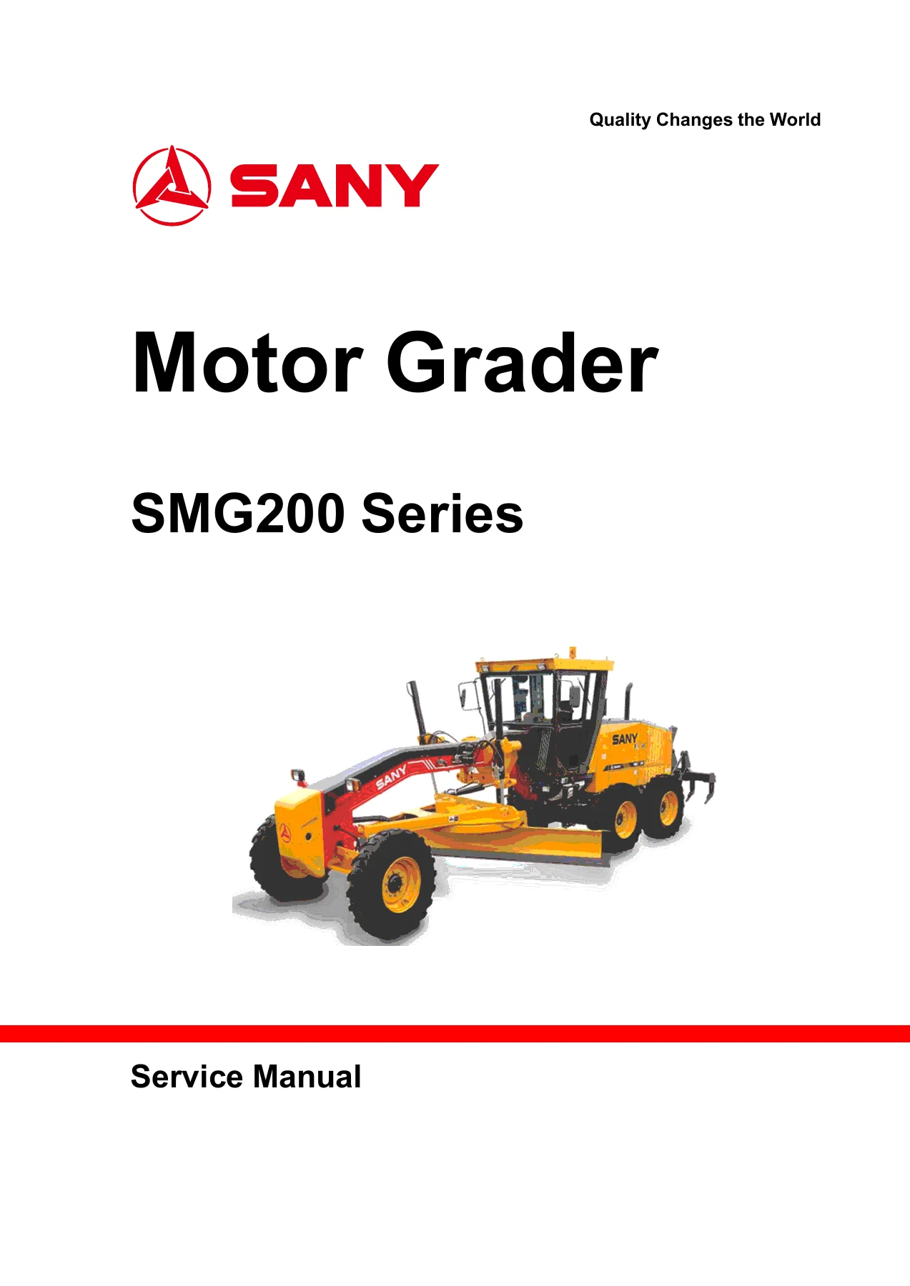
Complete 346-page service manual for the SANY SMG200 Series Motor Grader, including SMG200 and SMG200-LR(LA) coverage. It contains electrical and hydraulic schematics, mechanical working principles, extensive transmission and component disassembly and assembly procedures, troubleshooting guidance, torque and fitting data, and technical parameters.
Description
SANY SMG200 Series Motor Grader Service Manual – January 2021 PDF
The SANY SMG200 Series Motor Grader Service Manual – January 2021 PDF is a detailed 346-page service reference for the SMG200 Series. The manual specifically provides information for the SMG200 and SMG200-LR(LA), with dedicated electrical and hydraulic drawings and separate technical-parameter sections for these configurations. Its coverage moves from service safety and general repair practices into mechanical principles, climate-control systems, extensive component removal and installation work, transmission overhaul procedures, troubleshooting, and machine specifications.
A large part of this SANY SMG200 service manual is devoted to practical workshop procedures. The disassembly and assembly chapter documents operations with photographs, component identification, special-tool information, parts and auxiliary-material lists, tightening values, checks, and step-by-step instructions. This makes the manual particularly useful when work goes beyond routine inspection and requires dismantling, reassembly, adjustment, or diagnosis of major grader systems.
File Details
- Manual type: Service Manual
- Brand: SANY
- Series: SMG200 Series Motor Grader
- Models identified: SMG200 and SMG200-LR(LA)
- Language: English
- Pages: 346
- File format: PDF
- Manual date: January 2021
Workshop Repair and Service Coverage
The manual begins by establishing the service-preparation and safety practices used throughout the repair procedures. It covers machine shutdown and preparation, lockout/tagout precautions, hydraulic-pressure relief, electrical isolation, battery safety, handling of hot or pressurized fluids, and precautions for maintenance work. General information then provides tightening sequences and extensive torque references for metric and standard fasteners as well as many hydraulic fitting types.
The hydraulic connection information is unusually detailed. Coverage includes cone-seat connectors, O-ring boss fittings, flared connections, O-ring face-seal fittings, fittings in aluminum housings, SAE and metric high-pressure connections, split flanges, four-fastener flange fittings, DIN 20078 O-ring seals, adjustable banjo fittings, and O-ring boss fittings with shoulders. The manual supplies procedures and torque tables for these connections so repairs can be completed using the specified assembly practices rather than relying on general estimates.
Electrical and Hydraulic Schematics
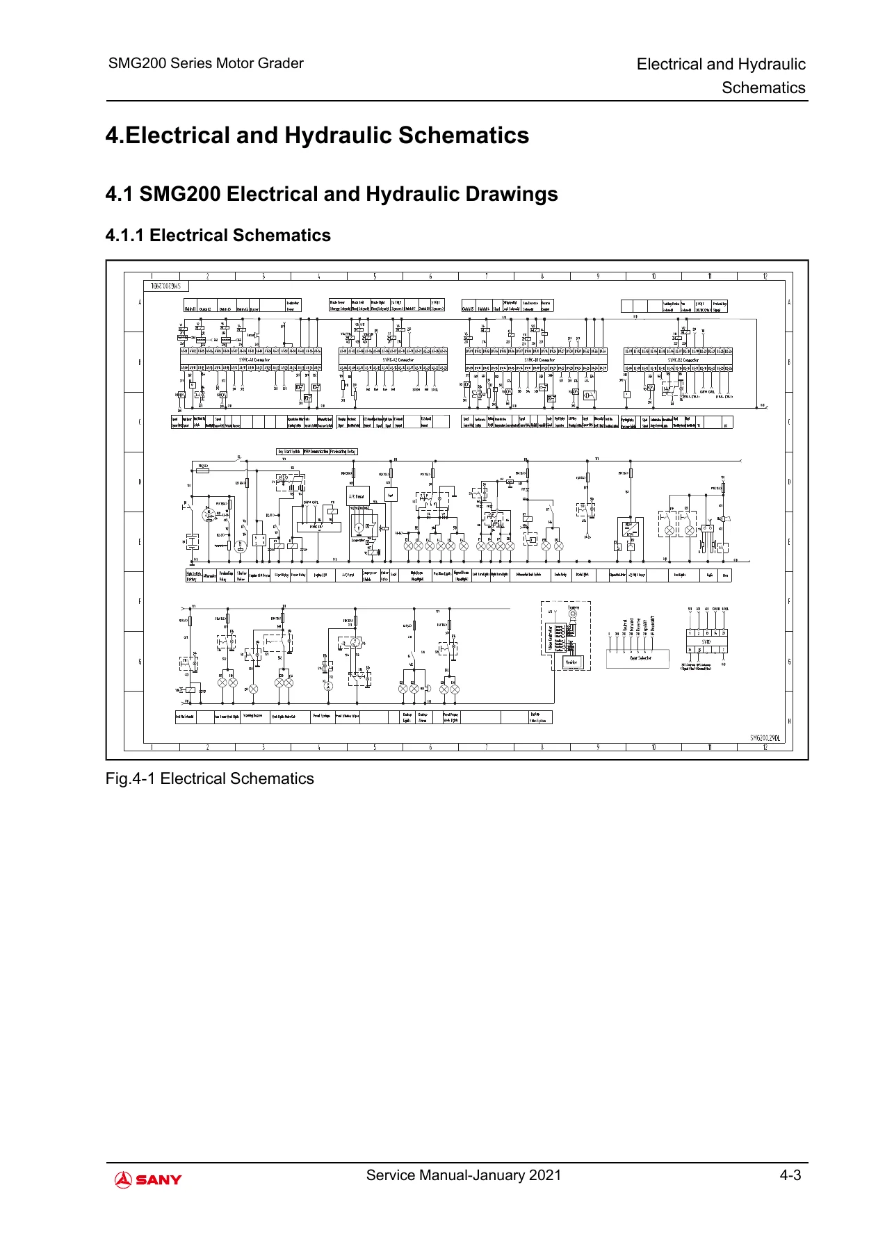
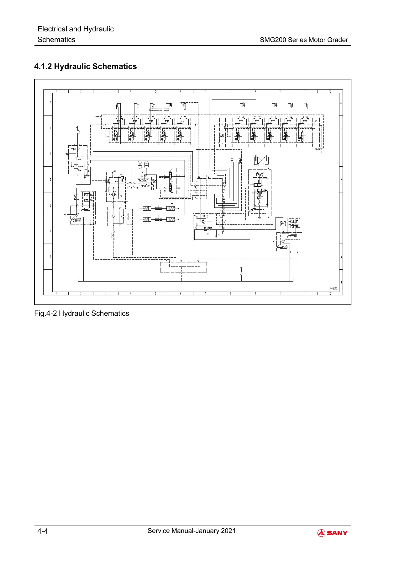
Dedicated schematic pages are supplied for both machine configurations. The SMG200 section contains an electrical schematic and hydraulic schematic, while SMG200-LR(LA) receives its own electrical and hydraulic drawings. These diagrams provide a system-level reference when tracing circuits, understanding component relationships, or following hydraulic paths during fault diagnosis and repair.
Transmission, Steering and Power Flow
The mechanical working-principle chapter explains transmission operation and illustrates the converter, clutches, shafts, output path and related elements. It also describes articulation steering, front-wheel steering, and the power-transmission route from the transmission through the output shaft, rear axle and tandem drive cases to the wheels. These explanations give useful context before moving into the much more extensive disassembly and assembly procedures later in the manual.
Transmission overhaul is one of the deepest areas of the SANY SMG200 Series Motor Grader Service Manual – January 2021 PDF. The manual provides procedures for transmission disassembly and reassembly, including the input shaft and second shaft. The work is supported by special-tool lists, component and parts information, photographs of the actual assemblies, lifting instructions, sealing and lubrication directions, inspection steps, clutch and friction-disc work, bearing installation, clearance checks and specified tightening torques. Individual procedures identify parts such as shaft assemblies, gears, bearings, seals, pumps, parking-brake components, sensors and the transmission harness.
Hydraulic Components, Axles, Steering and Grader Structure
Beyond the transmission, the manual covers removal, installation, disassembly or assembly of numerous hydraulic components used for grader functions. These include blade lift, blade side shift, blade tilt, circle side shift, articulation, wheel lean and steering cylinders, together with counterbalance valves, the steering valve, circle rotate motor, swivel joint, hydraulic fan motor, hydraulic fan pump and swing lock cylinder.
Axle and driveline work includes the transmission-to-rear-axle driveshaft, front wheel hub and knuckle assembly, front axle, drive chain, tandem wheel hub assembly, tandem drive sprockets, tandem drive case, tandem pivot, rear axle and planetary-drive components. Separate steering procedures address the steering shaft, steering-console tilt, steering wheel, steering console, front wheel lean bar, tie rod and toe-in checking and adjustment.
The frame and working-equipment procedures extend to the draft and circle frame, pin joints, swing frame, lift arms, blade pitch frame, blade side-shift wear inserts, circle drive gearbox and blade. The manual also contains removal and installation coverage for the front counterweight, cab, throttle pedal and inching pedal.
Electrical Components and Cab Climate System
Electrical component procedures include the batteries, air-filter restriction switch, fuel-level sensor, engine-coolant-level sensor, transmission-oil-temperature sensor, windshield-washer-fluid tank, radio, speakers and radio antenna. The heating and air-conditioning chapter separately explains the heating and refrigeration principles and identifies the operation of the compressor and clutch, condenser, evaporator, expansion valve, receiver-drier and pressure switch.
The HVAC material is supported by heating-cycle and air-conditioning-cycle diagrams as well as component illustrations. Climate-control coverage includes the panel, fan-speed control, heater control, temperature control, fresh-air and recirculation selection, and air-conditioning compressor control.
Chapters Covered
- 1 Foreword
- Introduction
- Record of Serial Number and Dealer Information
- Correction Request Form
- 2 Safety
- General Safety
- Machine Safety
- Machine Decals
- Maintenance Safety
- Job Safety
- 3 General Information
- Park and Prepare Machine for Service
- Tightening Sequence of Multiple Fasteners
- Metric Fastener Torque Values
- Standard Fastener Torque Values
- 37° and 30° Cone Seat Connectors
- O-ring Boss and O-ring Face Seal Fittings
- Flared Connections
- SAE and Metric Standard/High-Pressure Fittings
- Maintenance of Split Flanges
- Four Fastener Flange Fittings
- Metric 24° O-ring Seal DIN 20078
- Non-Restricted Banjo Fittings
- 4 Electrical and Hydraulic Schematics
- SMG200 Electrical and Hydraulic Drawings
- SMG200-LR(LA) Electrical and Hydraulic Drawings
- 5 Mechanical Working Principle
- Transmission
- Articulation Steering
- Front Wheel Steering
- Power Transmission
- 6 Heating and Air Conditioning
- Heating and Refrigeration Principle
- Compressor and Clutch
- Condenser, Evaporator and Expansion Valve
- Receiver-Drier and Pressure Switch
- Climate Control and Air Conditioning Diagrams
- 7 Disassembly and Assembly
- Transmission Disassembly and Assembly
- Input Shaft and Second Shaft Procedures
- Electrical Components Remove and Install
- Hydraulic Components Remove and Install
- Axle Remove and Install
- Steering System Remove and Install
- Frame Remove and Install
- Circle Drive Gearbox Remove, Install, Disassemble and Assemble
- Blade Remove and Install
- Front Counterweight Remove and Install
- Cab Remove and Install
- Throttle Pedal Remove and Install
- Inching Pedal Remove and Install
- 8 Troubleshooting
- Steering response, vibration, kickback and hard-steering faults
- Service-brake response, dragging, lockup, noise and delay
- Cooling-fan speed and operation faults
- Slow, drifting, erratic or inoperative hydraulic functions
- Work-pump displacement problems and hydraulic overheating
- 9 Technical Parameters
- SMG200 Machine Dimensions and Technical Specifications
- SMG200-LR(LA) Equipment Dimensions and Technical Parameters
Taken as a whole, these chapters give a technician both system understanding and procedure-level repair information. The manual connects diagrams and working principles with actual component work, while the troubleshooting section provides symptom-based guidance for steering, brakes, cooling-fan operation and hydraulic functions. Technical-parameter pages at the end provide machine dimensions, performance data, travel speeds, tire information and engine details for the configurations covered.
Troubleshooting and Technical Reference
The troubleshooting chapter is organized around recognizable machine symptoms rather than broad theory. Steering subjects include excessive steering-wheel turns, continued wheel movement after steering input stops, vibration, kickback, erratic steering, slow or hard steering and loss of steering. Brake problems include weak response, aggressive operation or lockup, dragging, cavitation or noise and delayed application.
Hydraulic diagnosis covers slow individual functions, hydraulic drift, no hydraulic operation, cavitation, excessive or insufficient operating speed, a work pump stuck at minimum or maximum displacement and hydraulic-system overheating. Cooling-fan troubleshooting addresses limited speed, full-speed-only operation and a fan that does not operate. This symptom-oriented material complements the hydraulic schematics and component procedures elsewhere in the manual.
The technical-parameter section identifies Cummins engine applications shown in the manual: the SMG200 table lists the QSC, while the SMG200-LR(LA) table lists the QSB6.7-C220. The section also provides grader dimensions, steering and articulation angles, blade movement data, travel speeds and other machine parameters for the applicable configuration.
Service the SMG200 with the Procedures and Data in One Manual
IMAGES PREVIEW
The SANY SMG200 Series Motor Grader Service Manual – January 2021 PDF supports substantial workshop work ranging from circuit tracing and fault diagnosis to transmission teardown, shaft and clutch work, hydraulic-cylinder service, axle and steering repairs, frame and blade-component removal, climate-system understanding and correct reassembly. Having the specified procedures, diagrams, tightening information, checks and machine parameters together helps reduce guesswork when diagnosing faults or rebuilding components. The manual is supplied as an instant PDF download after purchase, with no physical shipping required. It can be viewed on compatible computers, tablets and phones and pages can be printed when a paper reference is useful at the machine or workbench.


Reviews
There are no reviews yet.