
Komatsu GD555-3A GD655-3A GD675-3A Motor Grader Shop Manual PDF – SEBM021007 Download
Original price was: $59.95.$39.95Current price is: $39.95.
Complete Komatsu Shop Manual (SEBM021007) for GD555-3A, GD655-3A and GD675-3A motor graders, serial number 10001 and up. Covers general data, structure and function, testing and adjusting, disassembly and assembly, plus hydraulic and electrical circuits – delivered as an instant PDF download.
Description
Komatsu GD555-3A, GD655-3A & GD675-3A Motor Grader Shop Manual (SEBM021007)
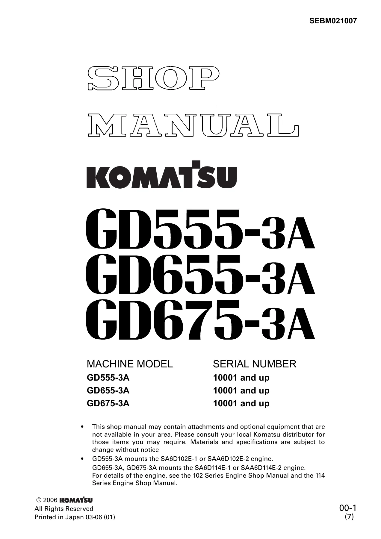
This is the complete Komatsu GD555-3A, GD655-3A and GD675-3A Motor Grader Shop Manual, issued under document number SEBM021007 and covering machines from serial number 10001 and up. It is the shop manual Komatsu service technicians work from to test, adjust, disassemble, assemble and repair these three motor grader models, and it is delivered to you as an instant PDF download.
The manual spans engine, power train, steering, brakes, hydraulics, work equipment and electrical systems in one document. GD555-3A machines mount the SA6D102E-1 or SAA6D102E-2 engine, while GD655-3A and GD675-3A machines mount the SA6D114E-1 or SAA6D114E-2 engine.
File Details
- Manual type: Shop Manual
- Brand: Komatsu
- Models covered: GD555-3A, GD655-3A, GD675-3A
- Serial number range: 10001 and up
- Document number: SEBM021007
- Language: English
- File format: PDF
- Page count: Approximately 680 pages
Chapters Covered
- 01 General
- 10 Structure, Function and Maintenance Standard
- 20 Testing and Adjusting
- 30 Disassembly and Assembly
- 90 Others
01 General
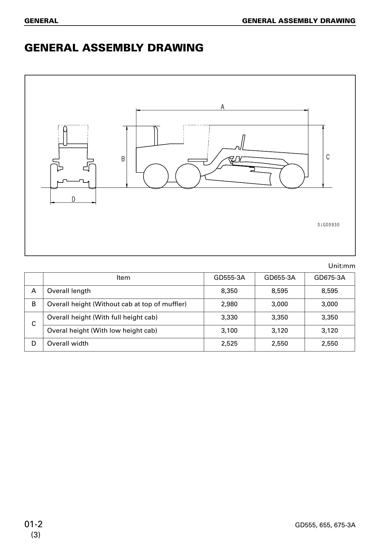
Begins with the general assembly drawing and overall machine dimensions, then moves into the full specification set for all three graders. You get machine weight and axle distribution, blade dimensions and blade load, all eight forward and four reverse travel speeds, maximum drawbar pull, gradeability, minimum turning radius, engine horsepower and torque ratings, torque converter and transmission data, tire sizes and inflation pressures, hydraulic pump discharge and set pressure, and cylinder bore and stroke figures for every work equipment function. A complete fuel, coolant and lubricant chart lists capacities together with the correct oil grade for each ambient temperature range. A dry weight table breaks the machine down into individual components – engine, radiator, transmission, final drive, tandem drive, blade, circle, drawbar, ripper, scarifier and more – which is what you need when planning a lift, a removal or a transport.
10 Structure, Function and Maintenance Standard
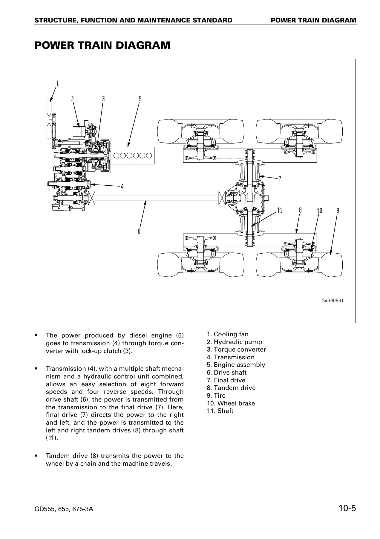
This is the theory-of-operation and wear-limit chapter. It explains how the accelerator linkage, fan drive, power train, torque converter and lock-up clutch, transmission, ECMV, final drive, tandem drive, steering valve, priority valve, front axle, brake system, hydraulic pump, CLSS control valve, blade float and accumulator circuits, circle rotation motor, hydraulic cylinders, circle drawbar, blade, scarifier, ripper and main frame actually work. Alongside each explanation sit the maintenance standards used to judge wear – standard sizes, tolerances, standard and limit clearances, spring free and installed lengths and loads, bearing preloads and tightening torques – so a removed part can be measured and accepted or rejected on the spot. The automatic shift control system, transmission controller, monitor, sensors and the engine starting, stopping and preheat circuits are covered in the same chapter.
20 Testing and Adjusting
Contains the standard value tables for the engine, chassis and electrical system, followed by the actual test and adjustment procedures. It shows you how to measure exhaust colour, blowby pressure, engine oil pressure and engine speed; how to test fan and air conditioner belt tension; how to measure torque converter stall speed; and how to check clutch oil pressure and torque converter pressures. You also get procedures for adjusting speed sensors, flushing the torque converter and transmission circuit, adjusting the accelerator control linkage, testing the brake disc, adjusting parking brake pad clearance, testing accumulator charge pressure, adjusting work equipment oil pressure and LS differential pressure, adjusting the PC valve, bleeding air from the hydraulic and brake circuits, measuring internal cylinder leakage, and charging the brake and work equipment accumulators with nitrogen. The chapter closes with the transmission controller learning and memory procedures, a diode checking procedure, and the method for moving a machine when the transmission valve fails.
30 Disassembly and Assembly
The largest chapter, and the one you will live in during a rebuild. It walks through removal and installation of the engine hood, radiator, fuel and hydraulic tanks, engine assembly (on its own or together with the transmission), transmission assembly, torque converter, final drive, side cases, differential gear, bevel gear and bevel pinion, operator’s cab and floor, steering valve, blade assembly, circle drawbar, circle rotation gear and the slip clutch-type rotary device. Each procedure carries the component weights, the special tools needed, the tightening torques, the clearances to check after press-fitting bearings, and the air-pressure checks used to confirm clutch operation before reassembly. Wiring and piping connection points, blind plug sizes and coating materials are listed where they apply.
90 Others
Provides the transmission hydraulic circuit and brake oil circuit diagrams, the full hydraulic circuit diagram in two parts, and the complete electrical circuit diagram set in six sheets for both the 10001 – 11000 and 11001 and up serial ranges. These are the schematics to trace a fault through when a pressure or electrical problem will not show itself with a gauge alone.
What You Can Do With This Komatsu Motor Grader Shop Manual
With this manual open you can service and repair the GD555-3A, GD655-3A and GD675-3A motor graders to the same procedures and tolerances used in a Komatsu service workshop. You can diagnose a transmission that will not upshift or downshift, a torque converter lock-up fault, a circle that will not rotate, a blade that drifts, a brake that lacks force, or a hydraulic system that is slow or noisy, by following the testing and troubleshooting charts rather than guessing. You can pull the transmission and torque converter, split the final drive, rebuild a clutch pack, re-set bevel gear backlash and tooth contact, and then verify your work against the standard clearances and preloads given in the manual. For a machine that works for a living, that difference between a measured repair and an assumed one is the difference between a comeback and a finished job.
IMAGES PREVIEW
This Komatsu motor grader shop manual is delivered as an instant PDF download after payment – no shipping, no waiting, no binder to lose. Read it on a laptop in the shop, on a tablet at the machine, or print the pages you need for the job at hand. Everything is in one file, so the same document that gets you through a routine adjustment also gets you through a full power train overhaul.
Reviews
There are no reviews yet.