
Komatsu HD255-5 Dump Truck Shop Manual – PDF Workshop Repair Guide
Original price was: $39.95.$23.95Current price is: $23.95.
Complete Komatsu HD255-5 shop manual covering serial numbers 1001 and up with SA6D125E-2 and SAA6D125E-3 engines. Includes structure and function, testing and adjusting, disassembly and assembly, maintenance standards, troubleshooting, and full hydraulic and electrical circuit diagrams.
Description
Komatsu HD255-5 Shop Manual – File Details
- Manual Type: Shop Manual (Chassis Volume)
- Brand: Komatsu
- Machine Model: HD255-5
- Serial Number Range: 1001 and up
- Engine Models: SA6D125E-2 and SAA6D125E-3
- Language: English
- File Format: PDF
- Page Count: Approximately 975 pages
- Document Sections: 01 General, 10 Structure and Function, 20 Testing and Adjusting, 30 Disassembly and Assembly, 40 Maintenance Standard, 90 Others
Chapters Covered in the Komatsu HD255-5 Shop Manual
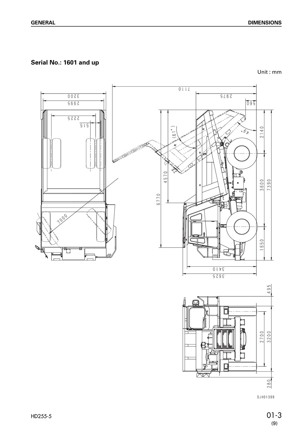
- 01 General – Dimensions, Specifications, Weight table, List of lubricants and coolant
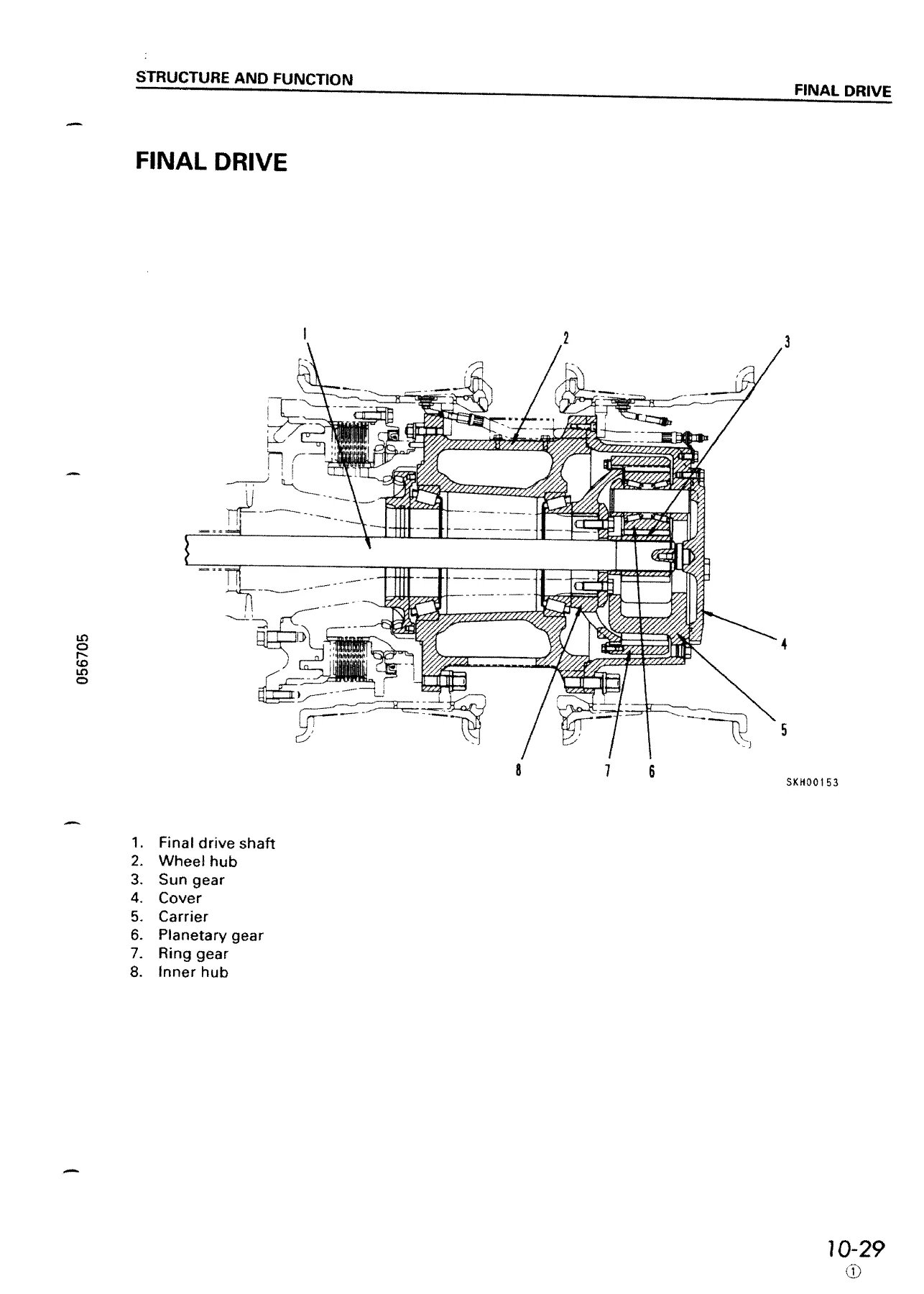
- 10 Structure and Function – Radiator, torque converter and brake oil cooler, aftercooler, power train skeleton, hydraulic system diagram for torque converter, transmission and brake cooling, torque converter, main relief valve, torque converter valve, transmission, transmission valve, ECMV (Electronic Control Modulation Valve), front axle, rear axle, differential, final drive, front brake, rear brake, parking brake, steering column, steering linkage, demand valve, crossover relief valve, steering valve, front suspension cylinder, rear suspension cylinder, air governor, safety valve, check valve, double check valve, hand brake valve (retarder control valve), brake valve, parking brake control valve, brake relay valve, parking relay valve, parking brake quick release valve, spring cylinder, slack adjuster, front brake chamber, rear brake chamber, air drier, air system diagram, hoist valve, hoist cylinder, automatic shift control system, automatic retarder valve, horn valve, wiper switch, sensors and switches, meter lamps
- 20 Testing and Adjusting – Standard value tables for engine related parts, chassis, and electrical system; testing and adjusting procedures for engine speed, valve clearance, compression pressure, blow-by, belt tension, oil pressure, exhaust gas temperature, exhaust gas color, fuel injection timing, air bleeding, torque converter stall speed, oil pressure of torque converter valve, brake pressure, parking brake performance, brake pad and disc wear, suspension cylinder, air governor set pressure, air drier inspection, hoist lever linkage, body positioner, hydraulic pressure in steering and hoist circuit, emergency travel procedures, flushing torque converter and transmission hydraulic circuit; troubleshooting for engine system (D mode), engine controller system (G mode), engine electrical system for start/stop (ENG mode), transmission controller system (A mode), meter panel system (E mode), pilot lamp system (F mode), machine air compressor air system (C mode), hydraulic and mechanical system (H mode), and ARSC automatic retarder speed controller system (R mode)
- 30 Disassembly and Assembly – Special tool list and sketches, starting motor, alternator, engine oil cooler, fuel injection pump, fuel supply pump, air compressor, air conditioner compressor, air conditioner condenser, water pump, aftercooler core, exhaust brake cylinder, turbocharger, nozzle holder, fuel injector, nozzle tip, cylinder head, engine front seal, engine rear seal, engine, radiator, oil cooler, output shaft, torque converter and transmission, PTO, transmission control valve (ECMV), transmission main relief valve, differential, front wheel, rear wheel, front brake caliper pad, front brake caliper, front wheel hub, final drive carrier, rear wheel brake, rear brake, front suspension cylinder, rear suspension cylinder, air governor, brake valve, parking brake spring cylinder, parking brake chamber, front brake chamber, rear brake chamber, slack adjuster, air drier (desiccant type), transmission control and retarder brake cooling pump and hoist and steering pump, emergency steering motor pump, steering valve, demand valve, relief valve, hoist valve, steering cylinder, hoist cylinder, dump body, transmission controller, engine controller, shift indicator controller, parking brake shoe
- 40 Maintenance Standard – Damper, torque converter, transmission, main relief valve, transmission valve and ECMV, front axle, differential, final drive, front brake, rear brake, parking brake, rear brake chamber, front brake chamber, slack adjuster, hydraulic pump, steering and hoist pump, steering cylinder, demand valve, crossover relief valve, hoist valve, hoist cylinder, steering linkage, rear axle support, front suspension cylinder, rear suspension cylinder
- 90 Others – Air circuit diagrams for standard and emergency brake specifications across serial number ranges, hydraulic circuit diagram for torque converter, transmission and brake cooling, steering and hoist hydraulic circuit diagrams, electric circuit diagrams for all serial number ranges, electric circuit diagram for transmission controller system, electric circuit diagrams for air conditioner
The Komatsu HD255-5 Shop Manual is the comprehensive technical reference for this rigid dump truck, covering every major system from the SA6D125E-2 and SAA6D125E-3 engines through the power train, brakes, suspension, steering, hydraulic and electrical systems. Each of the six main sections builds on the others: General establishes dimensions, capacities and lubricant specifications; Structure and Function explains how each component works with detailed cutaway illustrations; Testing and Adjusting provides the measurement procedures, standard values and troubleshooting flowcharts needed to diagnose problems; Disassembly and Assembly gives step-by-step removal and installation procedures with tightening torques and special tool requirements; Maintenance Standard supplies the wear limits and service data for inspection; and Others collects the complete hydraulic and electrical circuit diagrams.
What This Komatsu HD255-5 Shop Manual Enables You to Do
This manual supports the full range of service work on the HD255-5 dump truck. In the engine section you can adjust valve clearance, measure compression pressure and blow-by, test the torque converter stall speed, set fuel injection timing, and diagnose starting, performance, exhaust, oil consumption, overheating, noise and vibration complaints through the D-mode troubleshooting charts. The transmission and torque converter chapters cover the TCA43-11A torque converter, the F6 R1 planetary transmission, the ECMV control valves and the lock-up clutch system, with the A-mode troubleshooting charts linking symptoms to the electronic control system.
Brake and suspension work is covered with detailed procedures for the air-over-hydraulic front caliper disc brakes, the oil-cooled multiple disc rear brakes, the parking brake, the hydropneumatic suspension cylinders, the air governor, air drier and the complete air circuit. The hydraulic section includes the demand valve, steering valve, hoist valve and crossover relief valve, with pressure testing and adjustment procedures. Electrical troubleshooting spans the engine controller (G mode), meter panel (E mode), pilot lamp (F mode), air compressor air system (C mode), hydraulic and mechanical system (H mode) and the automatic retarder speed controller (R mode).
Why the Right Komatsu HD255-5 Workshop Manual Matters
The HD255-5 is a 25-tonne payload rigid dump truck, and the difference between a correct repair and an approximation shows up in component life, machine availability and safety. This shop manual gives the exact tightening torques for cylinder head bolts, drive shaft bolts, wheel nuts and brake caliper bolts; the correct oil and coolant capacities; the specified pressure settings for the main relief valve, torque converter relief valve, hoist relief and brake circuits; and the valve clearance and compression pressure limits. It also includes the emergency travel procedures for transmission valve failure and electrical system failure, which can get a machine out of a dangerous working area when it cannot be driven normally.
IMAGES PREVIEW
Instant PDF Delivery of the HD255-5 Repair Guide
This Komatsu HD255-5 shop manual is delivered as an instant PDF download after purchase. There is no shipping and no waiting for a physical book. The PDF works on any device that can display or print a PDF, including laptops, tablets and smartphones. You can print individual pages for use in the workshop, keep the complete manual on a device for reference, or search the text for a specific specification or procedure. The complete structure and function, testing and adjusting, disassembly and assembly, maintenance standard, troubleshooting and circuit diagram content is contained in a single file that covers serial numbers 1001 and up with both engine variants.


Reviews
There are no reviews yet.