
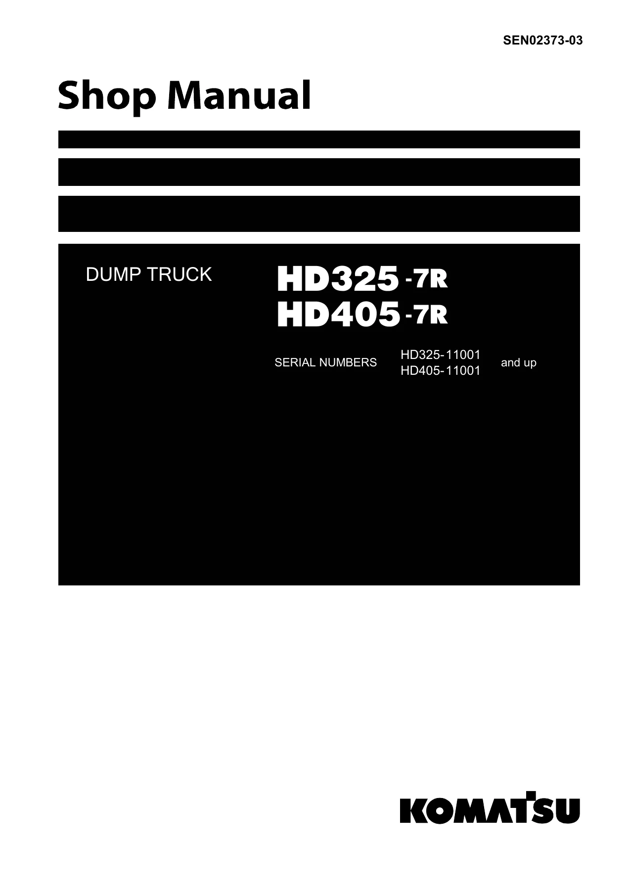
Komatsu HD325-7R HD405-7R Dump Truck Shop Manual SEN02373-03 – PDF Download
Original price was: $59.95.$39.95Current price is: $39.95.
Complete Komatsu HD325-7R and HD405-7R dump truck shop manual (SEN02373-03). Covers engine, power train, brakes, hydraulics, electrical, troubleshooting, disassembly and assembly for serial numbers 11001 and up. Instant PDF download.
Description
Komatsu HD325-7R & HD405-7R Shop Manual — SEN02373-03
This is the complete Komatsu shop manual for the HD325-7R and HD405-7R dump trucks, covering machines from serial number HD325-7R 11001 and up and HD405-7R 11001 and up. Published under document number SEN02373-03, this manual is the same technical reference used by professional service technicians for workshop repairs, scheduled maintenance, diagnostics and complete overhaul procedures.
The manual is written in English and delivered as a downloadable PDF. It covers every major system on the truck — engine and cooling, torque converter and transmission, axles and final drives, steering, brakes, suspension, hydraulic hoist and steering circuits, cab, and the full electrical and electronic control architecture. Whether you are servicing a single machine or running a fleet of HD325-7R and HD405-7R trucks, this manual gives you the Komatsu procedures, torque values, tolerances, and diagnostic workflows needed to do the job correctly.
File Details
- Manual type: Shop Manual (Service / Workshop)
- Brand: Komatsu
- Models covered: HD325-7R, HD405-7R
- Serial numbers: HD325-7R 11001 and up; HD405-7R 11001 and up
- Document number: SEN02373-03
- Language: English
- File format: PDF
- Publication date: 2008 (printed in Japan, 09-08)
Chapters Covered
- 00 Index and foreword
- 01 Specification
- 10 Structure, function and maintenance standard
- 20 Standard value table
- 30 Testing and adjusting
- 40 Troubleshooting
- 50 Disassembly and assembly
- 90 Diagrams and drawings
00 Index and Foreword
The opening section provides the manual composition table, revision history, a full table of contents, and the general information every technician needs before starting work. It covers safety notices, how to read the shop manual, explanation of terms used in maintenance standards, handling of electric equipment and hydraulic components, handling of engine connectors, how to read electric wire codes, precautions during operation, push-pull coupler procedures, standard tightening torque tables, and conversion tables. This is the reference foundation for the rest of the manual.
01 Specification
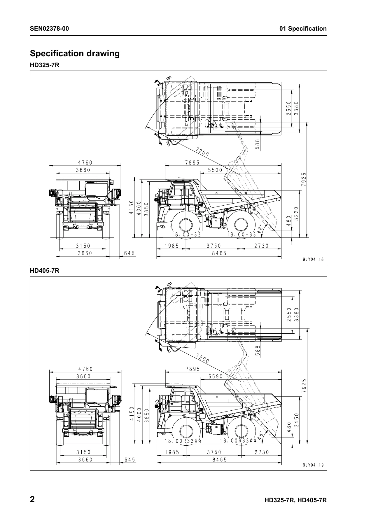
Contains the specification drawings for both the HD325-7R and HD405-7R, full specifications tables (weights, payload, dump body capacity, travel speeds, gradeability, dimensions, engine data), a weight table of major components and assemblies, and the fuel, coolant and lubricants chart with ambient temperature ranges and recommended Komatsu fluids. This is the section to consult when you need factory-rated capacities, load distribution figures, or approved fluid specifications.
10 Structure, Function and Maintenance Standard
The largest section of the manual, broken down by system:
- Engine and cooling system — radiator, oil cooler, aftercooler, output shaft, with specification data and standard values.
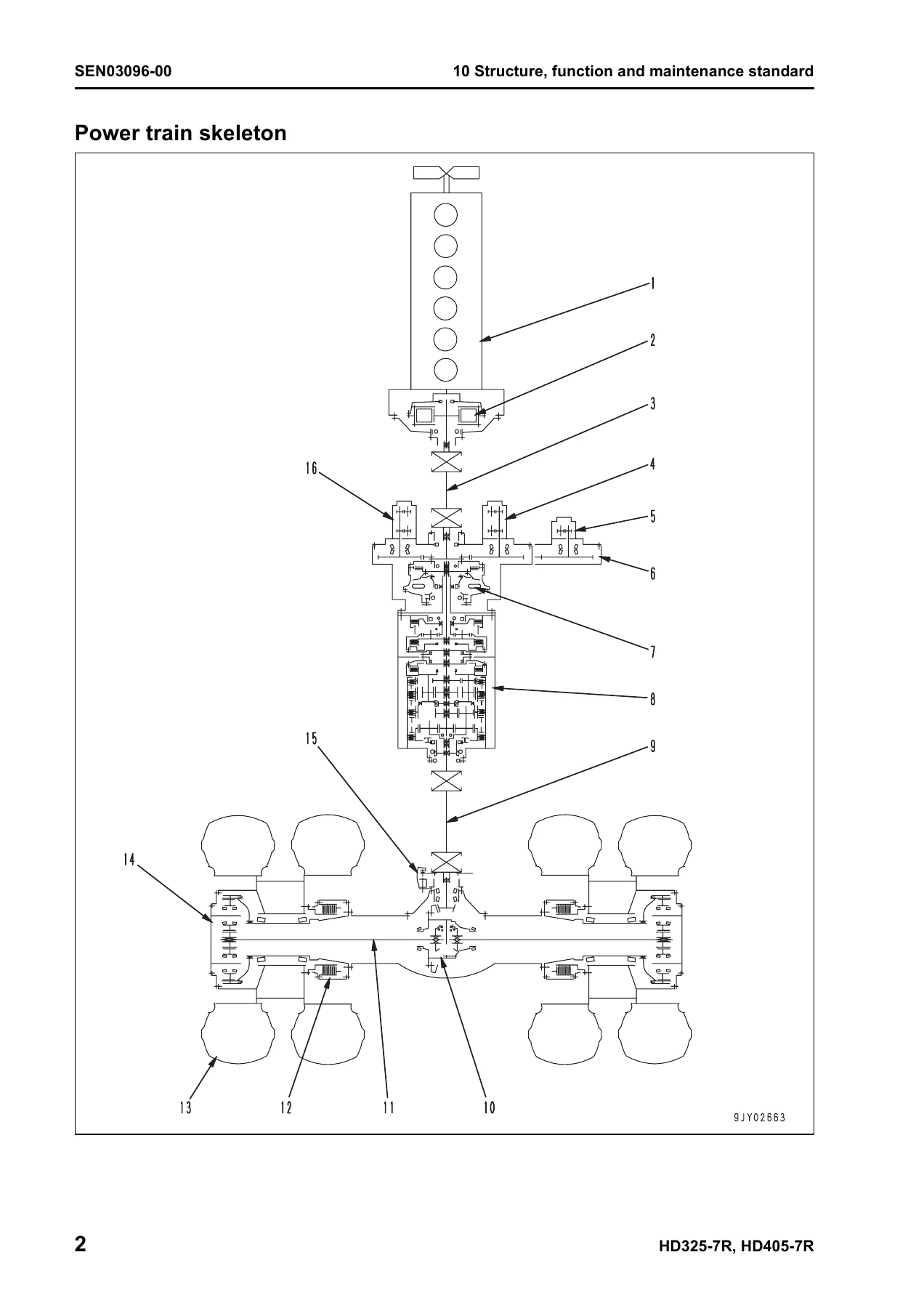
- Power train Part 1 — power train skeleton, drive shaft, torque converter and transmission hydraulic piping, power train charge pump, retarder cooling pump, torque converter, torque converter valve, transmission, transmission control valve, and ECMV. Includes power-flow schematics for each forward and reverse speed.
- Power train Part 2 — axle, differential, final drive, and wheel, with cross-sectional views and standard values.
- Steering system — steering column and steering linkage with clearance and bushing data.
- Brake system — brake piping, brake valve, secondary brake valve, relay valve, front brake cut valve, accumulator charge valve, accumulator, slack adjuster, brake, proportional reducing valve, parking brake, parking brake solenoid, and hand brake (retarder).
- Undercarriage and frame — suspension, suspension cylinder, rear axle support, and the variable damping selector valve.
- Hydraulic system — steering and hoist oil pressure piping diagram, dump body control, hydraulic tank, steering valve, cross-over relief valve, steering control valve, hoist valve, EPC valve, steering cylinder, hoist cylinder, and work equipment / steering pump.
- Cab and its attachments — ROPS cab, air conditioner, rear view monitor.
- Electrical system Parts 1–4 — machine monitor system, automatic shift control system, transmission controller, auto emergency steering system, retarder control system, dump control lever, auto suspension system, payload meter II (card type), sensors and switches, and KOMTRAX terminal system.
20 Standard Value Table
Provides the standard service value tables for the engine and for the machine. These are the reference values used during testing, adjusting, and troubleshooting to judge whether a component is within specification or has reached its service limit. Essential when checking wear, clearances, pressures, and performance.
30 Testing and Adjusting
Split into four parts covering the full range of measurement and adjustment procedures: tools for testing, adjusting and troubleshooting; engine speed, intake air pressure, exhaust temperature, exhaust gas color, valve clearance, compression pressure, blow-by pressure, engine oil pressure, fuel system handling and pressure/return/leakage testing, air bleeding, belt tension (alternator, fan, air conditioner compressor); torque converter stall speed, power train oil pressure, transmission speed sensor adjustment, brake oil pressure, accumulator nitrogen gas pressure and charging, brake performance, parking brake adjustment, brake circuit air bleeding, brake wear inspection, emergency parking brake release, suspension cylinder testing and adjusting (front, inverted rear, mode selector), steering and hoist circuit pressure, dump EPC circuit pressure, steering cylinder air bleeding, emergency body raising, body positioner sensor adjustment, high voltage circuit handling, transmission controller adjustment, and emergency escape procedures.
40 Troubleshooting
One of the most valuable sections for diagnosing faults. Includes the complete failure code table, fuse locations, general troubleshooting information, and detailed troubleshooting by failure code broken into five parts. Failure codes cover the transmission system (dual engagement, clutch slipping, ECMV solenoid issues, fill switch faults), engine controller codes (sensor circuits, injectors, common rail pressure, speed sensors), transmission and retarder controller codes (power supply, CAN communication, model selection), and sensor/actuator codes. Also includes E-mode troubleshooting of the electrical system, H-mode troubleshooting of the hydraulic and mechanical system, and S-mode troubleshooting of the engine. Each entry lists contents of trouble, action of controller, problem that appears on machine, possible causes, and standard values in normal state.
50 Disassembly and Assembly
Provides the special tools, procedures, precautions, tightening torques, coating materials, and quantities of oil, grease and coolant required for removal, installation, disassembly and assembly of every major component. Covers the engine and cooling system, power train Part 1 and Part 2, steering system, brake system, undercarriage and frame, hydraulic system, body, cab and its attachments, and electrical system. Includes component weights, forcing screw procedures, press-fit temperatures, and step-by-step instructions with figures.
90 Diagrams and Drawings
Contains the hydraulic circuit diagrams (power train hydraulic circuit, steering and hoist hydraulic circuit for early and later serial ranges, brake hydraulic circuit) and the complete electrical circuit diagrams (inside cab 1–5, outside cab 1–3) plus connector tables and arrangement drawings. These schematic diagrams are essential for tracing circuits, understanding hydraulic flow, and diagnosing electrical faults.
What This Komatsu HD325-7R / HD405-7R Shop Manual Enables You to Do
With this manual in hand, you can perform the full range of professional service work on your HD325-7R or HD405-7R dump truck:
- Run scheduled maintenance — fluid changes, filter replacement, belt tension checks, valve clearance adjustment — using the correct capacities and intervals.
- Diagnose faults accurately using the failure code tables and step-by-step troubleshooting charts, narrowing down electrical, hydraulic and mechanical issues instead of guessing.
- Test and adjust every major system — engine speed, torque converter stall, transmission oil pressure, brake oil pressure, steering and hoist circuit pressure, suspension cylinder nitrogen charge — using the specified values and procedures.
- Remove, disassemble, inspect, reassemble and install components from the engine, torque converter, transmission, differential, final drive, brakes, suspension, hydraulic cylinders and electrical system using the correct special tools and tightening torques.
- Understand how the machine is built — power flow, hydraulic circuits, electrical networks and electronic control systems — through the structure and function sections.
- Trace hydraulic and electrical circuits using the complete diagrams and drawings, including the connector pin-out tables.
Why This Manual Matters
Heavy equipment repairs are expensive, and a wrong torque value, an incorrect oil capacity, or a misdiagnosed fault can lead to premature failure, downtime, and costly damage. The Komatsu HD325-7R / HD405-7R Shop Manual gives you the manufacturer’s exact specifications, procedures and diagnostic logic. It removes guesswork from maintenance and repair, helps you avoid unnecessary parts replacement, and lets you complete jobs confidently the first time.
Whether you are a fleet maintenance manager, an independent mechanic, or an owner-operator who prefers to do your own servicing, having the correct Komatsu shop manual for your serial number range is the difference between a repair that lasts and one that comes back.
IMAGES PREVIEW
Instant PDF Delivery — No Shipping, No Waiting
This listing is for the downloadable PDF version of the manual. After payment you receive the file immediately — no physical shipping, no customs delays, no waiting for a package. The PDF can be viewed on any device (PC, Mac, tablet, smartphone), printed for the workshop if you prefer paper, and stored for quick reference whenever you need it. Keep it on a USB stick, save it to your service laptop, or print only the pages you need for the job at hand.
If you are maintaining a Komatsu HD325-7R or HD405-7R dump truck, this shop manual is the technical reference you will reach for again and again.



Reviews
There are no reviews yet.