
Komatsu PC300-7 PC300LC-7 PC350-7 PC350LC-7 Shop Manual SEBM025804 PDF
Original price was: $44.95.$26.95Current price is: $26.95.
Comprehensive 643-page Komatsu shop manual for PC300-7, PC300LC-7, PC350-7 and PC350LC-7 machines, covering chassis specifications, structure and function, testing and adjusting, troubleshooting, disassembly and assembly, hydraulic systems, electrical circuits and service standards. Covers PC300-7/PC300LC-7 serial 40001 and up and PC350-7/PC350LC-7 serial 20001 and up.
Description
Komatsu PC300-7 PC300LC-7 PC350-7 PC350LC-7 Shop Manual SEBM025804 PDF
The Komatsu PC300-7 PC300LC-7 PC350-7 PC350LC-7 Shop Manual SEBM025804 PDF is a detailed workshop reference for service, inspection, adjustment, troubleshooting, removal, installation, disassembly and assembly work on the covered machines. It applies to PC300-7 and PC300LC-7 machines from serial number 40001 and up, and PC350-7 and PC350LC-7 machines from serial number 20001 and up. The manual combines machine specifications and maintenance standards with extensive hydraulic, control, travel, swing, work-equipment and electrical information.
Komatsu identifies the SAA6D114E engine for these models. The manual includes engine-related specifications, tests and selected removal and installation procedures, but it also states that detailed engine information is contained in the separate 114 Series Engine Shop Manual. This makes SEBM025804 especially useful as the chassis and machine-system shop manual for the PC300/350(LC)-7 series while clearly defining where separate engine-series information may be required.
File Details
- Manual type: Shop Manual
- Brand: Komatsu
- Models: PC300-7, PC300LC-7, PC350-7, PC350LC-7
- Serial coverage: PC300-7 and PC300LC-7: 40001 and up; PC350-7 and PC350LC-7: 20001 and up
- Engine identified: SAA6D114E
- Language: English
- Pages: 643
- File format: PDF
- Document number: SEBM025804
- Publication marking: 2002; Printed in Japan 11-02 (01)
Machine and Service Information
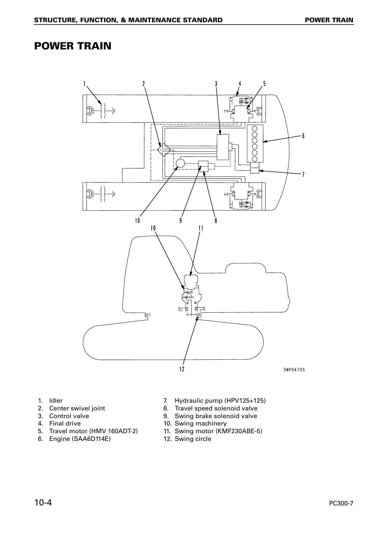
The manual begins with dimensional drawings, working ranges, specifications, component weights, and fuel, coolant and lubricant data. The specification pages distinguish the standard and LC configurations and provide values for machine dimensions, operating weight, digging ranges, travel and swing performance, engine data, electrical equipment, undercarriage arrangement and hydraulic equipment. The SAA6D114E data includes engine type, bore and stroke, displacement, output and torque figures, while hydraulic pages identify major components such as the HPV125+125 main pump, HMV160ADT-2 travel motor and KMF230ABE-5 swing motor.
Maintenance-standard sections go beyond basic component identification. They show construction, operating principles, clearances, wear limits, spring dimensions, gear backlash, track and roller criteria, hydraulic-cylinder clearances and work-equipment pin and bushing limits. This gives the technician reference values for deciding whether parts are within standard, require adjustment, or have reached a repair limit.
Hydraulic, Control and Electronic Coverage
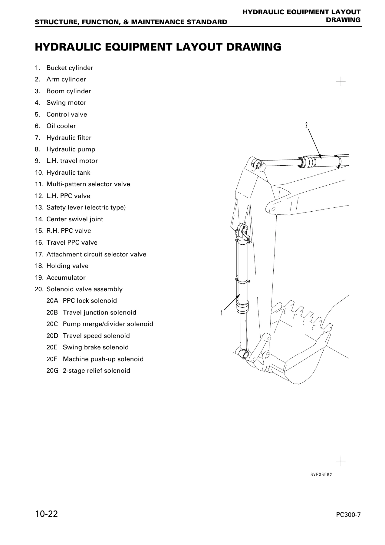
A large portion of this Komatsu PC300-7 and PC350-7 shop manual is devoted to hydraulic operation. It explains the hydraulic pump, LS and PC control, variable-volume control, the control valve, Closed Center Load Sensing System (CLSS), self-pressure reducing valve, travel and swing circuits, PPC valves, solenoid valves, hydraulic drift prevention, quick-return functions and attachment circuit selection. Diagrams trace component layouts and oil flow so that pressure checks and operating symptoms can be related to the system involved.
The electronic-control material includes engine control, the electronic control system, multi-monitor and 7-segment monitor functions, sensors and service-menu functions. Testing and troubleshooting sections use monitor information, service codes, failure histories, wiring checks, resistance and voltage measurements, and system-specific diagnostic procedures. The final Others section provides a hydraulic circuit diagram plus four parts of the electrical circuit diagram.
Chapters Covered
- 01 General
- Specification dimension drawings and working ranges
- Specifications for PC300-7 / PC300LC-7
- Specifications for PC350-7 / PC350LC-7
- Weight tables for the covered models
- Fuel, coolant and lubricants
- 10 Structure, Function and Maintenance Standard
- Engine related parts; radiator, oil cooler and aftercooler
- Power train, final drive, swing machinery and swing circle
- Track frame and recoil spring; idler, carrier roller, track roller and track shoe
- Hydraulic equipment layout, hydraulic tank and HPV125+125 hydraulic pump
- Variable volume valve, control valve and CLSS
- Self pressure reducing valve and swing motor
- Reverse prevention valve and center swivel joint
- HMV160ADT-2 travel motor and travel junction valve
- Travel PPC shuttle valve and valve control
- Work equipment / swing PPC valve, travel PPC valve and service PPC valve
- Solenoid valve, PPC accumulator and return oil filter
- Boom hydraulic drift prevention valve, quick return valve and lift check valve
- Attachment circuit selector valve, hydraulic cylinders and work equipment
- Air conditioner, engine control and electronic control system
- Multi-monitor system, 7-segment monitor system and sensors
- 20 Testing and Adjusting
- Standard value tables for engine-related and chassis-related parts
- Tools for testing, adjusting and troubleshooting
- Engine RPM inspection and adjustment; air boost pressure and exhaust gas color measurement
- Valve clearance, compression pressure, blow-by pressure and fuel injection timing checks
- Engine oil pressure, engine speed sensor and air-compressor belt inspection
- Swing-circle bearing clearance, track shoe tension and sprocket wear
- Hydraulic pressure checks for work equipment, swing and travel
- Control circuit, pump PC control and pump LS control pressure checks
- Solenoid valve and PPC valve output pressure measurements
- Work equipment and swing PPC valve adjustment
- Hydraulic drift checks, residual-pressure release, oil-leakage measurement and air bleeding
- Diode inspection, multi-monitor special functions and 7-segment monitor functions
- Electrical-system troubleshooting preparation and detailed troubleshooting
- 30 Disassembly and Assembly
- How to read the procedures, operating precautions and special tool list
- Starting motor and fuel injection pump assemblies
- Engine front seal, engine rear seal and cylinder head assembly
- Radiator and hydraulic oil cooler assemblies
- Engine and hydraulic pump assemblies
- Final drive; swing motor and swing machinery
- Carrier roller, track roller, idler and recoil spring assemblies
- Sprocket, track shoe and swing circle assemblies
- Revolving frame and center swivel joint assemblies
- Hydraulic tank, control valve and hydraulic pump assemblies
- Work equipment PPC valve and travel PPC valve assemblies
- Hydraulic cylinder and work equipment assemblies
- Air conditioner unit, counterweight and operator cab assemblies
- Monitor and governor pump controller assemblies
- 90 Others
- Hydraulic circuit diagram
- Electrical circuit diagram, parts 1 through 4
Taken together, these chapters let a technician move from identifying the machine and checking standard values to understanding system operation, measuring pressures and performance, tracing faults, and carrying out component removal or overhaul procedures. The maintenance-standard material is particularly valuable during inspection because it supplies concrete criteria for wear, clearance and adjustment rather than relying only on visual judgement.
Repair Procedures and Diagnostic Support
The disassembly and assembly chapter is built around workshop jobs. Procedures cover removal and installation of major machine assemblies, along with dedicated disassembly and reassembly instructions where the manual provides them. Special tools, component weights, tightening instructions, oil refilling, air bleeding, sealing and lubrication notes are included around relevant operations. Examples of covered areas include final drives, swing machinery, undercarriage components, center swivel joint, hydraulic tank, control valve, hydraulic pump, cylinders and work equipment.
Testing and adjusting content supports fault diagnosis before parts are removed. Standard-value tables establish reference conditions, while dedicated procedures address engine-related measurements, swing and travel behavior, hydraulic pressures, PPC outputs, pump control pressures, work-equipment drift and electronic monitoring. The troubleshooting material then links machine symptoms and service information to checks of mechanical, hydraulic and electrical causes. This structure is useful when the goal is to confirm the fault first and avoid replacing components without a measured basis.
Get the Correct PC300/350(LC)-7 Service Reference
The Komatsu PC300-7 PC300LC-7 PC350-7 PC350LC-7 Shop Manual SEBM025804 PDF supports a wide range of workshop tasks, from checking service limits and hydraulic pressures to diagnosing control faults, removing assemblies, rebuilding selected components and following specified installation procedures. Having the correct serial-range manual matters because repair decisions depend on the right procedures, tightening information, circuit layouts, clearances, pressures and inspection standards for the machine being serviced.
After payment, the manual is delivered as an instant PDF download with no physical shipping. It can be opened on any compatible device, including phones, tablets and computers, kept available for workshop reference, and printed when a paper copy of selected procedures or diagrams is more convenient.



Reviews
There are no reviews yet.