★ TRUSTED BY 321,897+ PROFESSIONALS WORLDWIDE
🏢
Trusted Business
Verified & Licensed
🛡️
Virus Free Files
100% Safe Downloads
🔒
Secure Payment
SSL Protected
⚡
Instant Delivery
Available Immediately
Sale!

Komatsu 730E Dump Truck Shop Manual – CEBM018000 Complete Service & Repair PDF

Original price was: $49.95.Current price is: $29.95.

The complete Komatsu 730E Dump Truck Shop Manual (CEBM018000) covering serial numbers A30427 & UP. This 1102-page PDF service manual provides full disassembly, assembly, testing, adjustment, and troubleshooting procedures for the 730E electric drive off-highway truck, powered by the Komatsu SSA16V159 engine and equipped with GE GTA-22 alternator and GE 788 wheel motors.

⚡
Instant PDF Download
Available immediately
💾
Save to Your Device
Download & keep forever
🛡️
Antivirus Scanned
100% virus-free
🌍
Trusted Worldwide
175,000+ customers

Description

Komatsu 730E Dump Truck Shop Manual – CEBM018000

This is the full Komatsu 730E Dump Truck Shop Manual with document number CEBM018000, covering serial numbers A30427 & UP. The manual is written for the service technician and is designed to help personnel become fully knowledgeable of the truck and all its systems in order to keep it operating safely and efficiently. Every major serviceable component has its own dedicated section, with disassembly, service, and reassembly procedures provided in full detail.

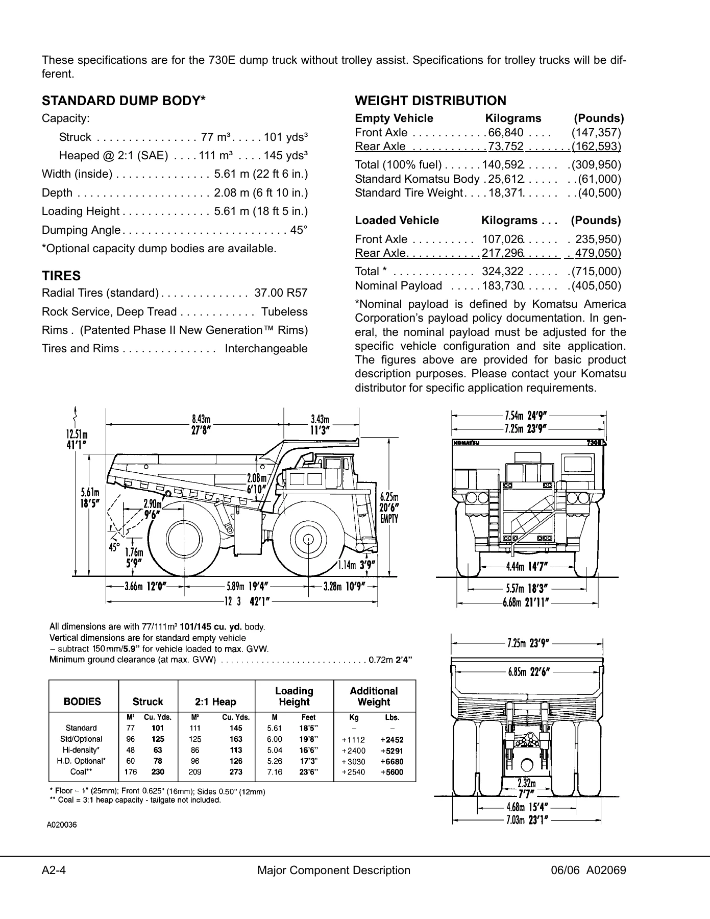
The 730E is an electric drive, off-highway rear dump truck with a gross vehicle weight of 324,322 kg (715,000 lbs) and a nominal payload of 185 t (203 tons). It is powered by the Komatsu SSA16V159 engine rated at 2000 HP (1492 kW), driving a General Electric GTA-22 alternator and two General Electric 788 wheel motors. All procedures, specifications, torque values, and safety notices in this manual apply directly to that machine.

File Details

  • Manual Type: Shop Manual (Service & Repair)
  • Brand: Komatsu
  • Model: 730E Dump Truck
  • Document Number: CEBM018000
  • Serial Numbers Covered: A30427 & UP
  • Language: English
  • File Format: PDF
  • Page Count: 1102 pages

Chapters Covered

This Komatsu 730E Shop Manual is organised into the following major sections:

  • Section A – General Information: Major components and specifications, general safety and operation, warnings and cautions, standard torque charts and conversion tables, storage procedures.
  • Section B – Structures: Structural components (ladders, grille and hood, right-hand deck, center deck, left-hand deck), dump body, fuel tank (removal, repair, cleaning, installation, fuel gauge sender, low fuel sender, tank breather valve).
  • Section C – Engine, Fuel, Cooling and Air Cleaner: Power module (general information, removal, installation), cooling system (radiator removal, service, installation, fill procedure, repair, pressure testing, coolant system troubleshooting), power train (alternator removal and installation, engine removal and installation), air cleaners (service checks, filter element replacement, main filter cleaning, precleaner section, air intake troubleshooting), fan drive clutch (general description, components, operation modes, maintenance, troubleshooting, disassembly, reassembly, inspection).
  • Section D – Electric System (24 VDC, Non-Propulsion): 24VDC electric supply system (batteries, maintenance, troubleshooting, battery charging alternator, 24VDC electric start system, cranking motors, engine prelub system), 24VDC electrical system components (passenger seat base compartment, battery equalizer box, body-up switch, hoist limit switch, relay boards, diode board, circuit breakers), battery charging alternator (testing, regulator testing, bench testing, static testing, field coil tests, stator tests, thermal switch test, troubleshooting, repair), VHMS components, VHMS software, VHMS checkout and troubleshooting, VHMS forms, Payload Meter III (operation, component description, operator display and switch, payload operation and calculation, haul cycle data, PC software, downloading, troubleshooting, checkout procedure).
  • Section E – Electric Propulsion and Control: Electrical propulsion components (general system description, control system, FL275 panel, card replacement, computer description, software, two-digit display panel, portable test unit, configuration files, programming the truck, statistical data, electrical control cabinet, abbreviations, card identification), Statex III electrical system checkout procedure (communications port check, sequence tests, control system self-test, throttle system check and adjustment, retard system check and adjustment, reverser and propulsion contactors check, retard contactors operation check, ground fault sensing check, ground fault in retard operation check, override operation check, anti-reversal function check, overspeed retard operation check, hoist interlock operation check, motor blower fault light operation check, digital input/output signals test, analog input signals test, speed event checks, retard speed control system check, load test using truck retard grids, motor field current check in retarding, miscellaneous component test and adjustment, miscellaneous charts).
  • Section G – Drive Axle, Spindle, and Wheels: Tires and rims (general information, handling tires, tire maintenance, storing tires, front tires and rims, rear tires and rims, rim, tire removal, rim and tire preparation, lubricants, tire installation), front wheel hub and spindle (removal, installation, disassembly, cleaning and inspection, assembly, wheel bearing adjustment, steering cylinders and tie rod, spherical bearing wear limits, toe-in adjustment), rear axle housing attachment (pivot pin, pivot eye bearing, pivot eye repair, anti-sway bar), rear axle housing (removal, installation, wheel motor removal and installation, bumper pad).
  • Section H – Suspensions: Front suspension (removal, installation, turn-of-the-nut tightening procedure, disassembly, cleaning and inspection, assembly, suspension pressure test), rear suspensions (removal, installation, disassembly, cleaning and inspection, assembly, suspension pressure test), oiling and charging procedures (general, equipment list, Hydrair charging kit, front suspension oiling and nitrogen charging, rear suspension oiling and nitrogen charging, oil and nitrogen specifications).
  • Section J – Brake Circuit: Brake circuit (general description, service brake circuit, secondary braking and automatic apply, parking brake circuit, brake lock circuit, warning circuit), brake circuit component service (brake valve, rebuild criteria, removal, installation, disassembly, cleaning and inspection, assembly, differential pressure switch, valve bench test and adjustment, hydraulic brake accumulators, brake accumulator charging, accumulator storage), brake circuit check-out procedure (equipment required, initial system set-up, parking brake, service brakes, brake lock/secondary, low brake pressure and auto apply, reapplications, differential pressure switch, troubleshooting, check-out procedure, hydraulic brake system data sheet), Rockwell wheel speed front disc brakes (brake caliper removal, installation, disassembly, cleaning and inspection, assembly, brake lining replacement, front service brake burnishing, brake bleeding procedure), Rockwell armature speed rear disc brakes (caliper, disc, and parking brake removal and installation, caliper piston, functional test of piston assembly, brake lining replacement, service brake burnishing, brake bleeding procedure), Rockwell disc parking brake (general information, lining thickness inspection, removal, installation, adjustment, disassembly, cleaning and inspection, assembly, lining replacement, burnishing procedure, brake bleeding procedure).
  • Section L – Hydraulic System: Hydraulic system (general information, hoist circuit operation, steering circuit operation), hydraulic component repair (hoist pump removal, installation, disassembly, inspection, assembly, troubleshooting; hydraulic tank filling, removal, installation, strainer and diffuser), steering circuit (operation, component description, steering control valve, unloader valve, bleed-down manifold valve, flow amplifier, flow amplifier system operation, steering pump, high pressure filter, accumulators, low precharge warning switch), steering control unit (general information, removal, installation, rebuild, disassembly, cleaning and inspection, assembly, steering/brake pump removal, installation, disassembly, inspection, assembly), steering circuit component repair (bleed-down manifold, accumulator, flow amplifier, steering cylinders, troubleshooting chart), hoist circuit (operation, component description, hydraulic tank, hydraulic pump, high pressure filter, hoist valve, hoist pilot valve, bleed-down manifold, counterbalance manifold, hoist-up limit solenoid, pilot operated check valve, hoist valve operation, float operation, power up operation, hold operation, power down operation), hoist circuit component repair (hoist valve, inlet section, rear spool section, hoist pilot valve, hoist up limit solenoid valve, hoist cylinders, counterbalance manifold), hydraulic system filters (hoist circuit filter, steering circuit filter, indicator switch), hydraulic check-out procedure (initial start up and flushing, component checkout and adjustment, adjustment procedure for hoist counterbalance cartridge valve, oil cleanliness check, disabled truck dumping procedure).
  • Section M – Options and Special Tools: Engine oil heaters (general information, troubleshooting, heater element removal and installation), special tool group (accumulator charging valve, roll-out assembly, offset wrench, torque adapter, handle, seal installer, sleeve alignment tools, harness, quick disconnect coupling, sockets and adapters, eye bolt, accumulator wrench, miscellaneous tools, pusher tools, front spindle removal).
  • Section N – Operator’s Cab: Truck cab (description, removal, installation, cab door removal, installation, adjustment, door jam bolt adjustment, door handle plunger adjustment, replace door glass, replace door window regulator, replace door handle or latch assembly, door and door hinge seal replacement, door opening seal removal, installation, glass replacement, adhesive-bonded windows, windshield and rear glass removal and installation), cab components (windshield wipers, wiper motor replacement, wiper arm replacement, wiper linkage replacement, windshield washer operation and service), operator comfort (heater/air conditioner controls, components, air conditioning system, principles of refrigeration, air conditioner system components, electrical circuit, thermostat, compressor clutch, Trinary switch, system servicing, service tools and equipment, system performance test, system oil, refrigerant, system leak testing, recovering and recycling the refrigerant, system repair, component replacement, evacuating the system, charging the A/C system, air conditioner drive belt, pulley alignment, belt tension, troubleshooting, preventative maintenance schedule), operator controls and equipment (steering wheel and controls, steering wheel, horn button, tilt/telescope lever, multi-function turn signal switch, steering column removal, inspection, installation, pedals, service brake pedal, dynamic retarder pedal, throttle pedal, overhead panel controls and components, grade/speed warning chart, radio speakers, warning alarm buzzer, cab radio, warning lights dimmer control, warning/status indicator light panel, air cleaner vacuum gauges, windshield wipers, center console, truck controls, F-N-R selector switch, hoist control lever, console switches and controls, payload meter, cab climate control, heater/air conditioner vents, operator seat adjustment, instrument panel, control symbols, control switches and gauges, overhead status/warning indicator light panel, Centry fuel system diagnostics, Vehicle Health Monitoring System).
  • Section P – Lubrication and Service: Lubrication and service (general information, hydraulic tank service, cooling system, 10 hour lube and maintenance checks, 50 hour, 100 hour, 250 hour, 500 hour, 1000 hour, 1500 hour, 2500 hour, 5000 hour, 10,000 hour lubrication and maintenance checks), automatic lubrication system (general description, system components, filter assembly, hydraulic motor and grease pump, reservoir, fixed pressure reducing valve, flow control valve, solenoid valve, vent valve, 24VDC lubrication cycle timer, time delay module, pump cutoff pressure switch, unloader valve, pressure switch, pressure gauge, manual override button, injectors, system operation, pressure failure detection circuits, general instructions, lubricant required, system priming, lubricant pump, filter and reservoir, injectors, system checkout, lubrication cycle timer check and adjustment, preventive maintenance inspection, pump rebuild, vent valve rebuild, troubleshooting chart), motorized wheel maintenance schedule (axle box, armature area, at tire change, generator/alternator, grid blower motor, control equipment checks, auxiliary equipment and air ventilation system, vehicle operations tests).
  • Section R – System Schematics: Hydraulic brake system schematic, hydraulic system schematic, electrical schematic (33 sheets covering power distribution, retarding grids, drive system control circuits, two-digit display, G.E. analog inputs, G.E. digital inputs and lube control, rear tail lights and dimmer control, 5 minute timer and spares, windows, radio, gauges, contactor feedback, contactor coil, machine control circuits, accelerator and retard pedals, hydraulic controls and alarms, heater/AC and windshield wiper controls, light control circuits, instruments and diagnostic ports, modular mining dispatch, Cummins K2000 engine, Payload Meter III installation, Cummins QSK engine with HVP prelube, wiper turn signal, wiper washer turn signal, heater/AC controls, power retarding), VHMS system schematic (5 sheets).

Complete PDF Bookmark Tree

Complete Bookmarks

The complete bookmarks in the “Komatsu 730E Dump Truck Shop Manual – CEBM018000 Complete Service & Repair PDF” are as follows:

MAIN MENU
COVERp. 1
FOREWORDp. 5
TABLE OF CONTENTSp. 7
SECTION A – GENERAL INFORMATION – INDEXp. 9
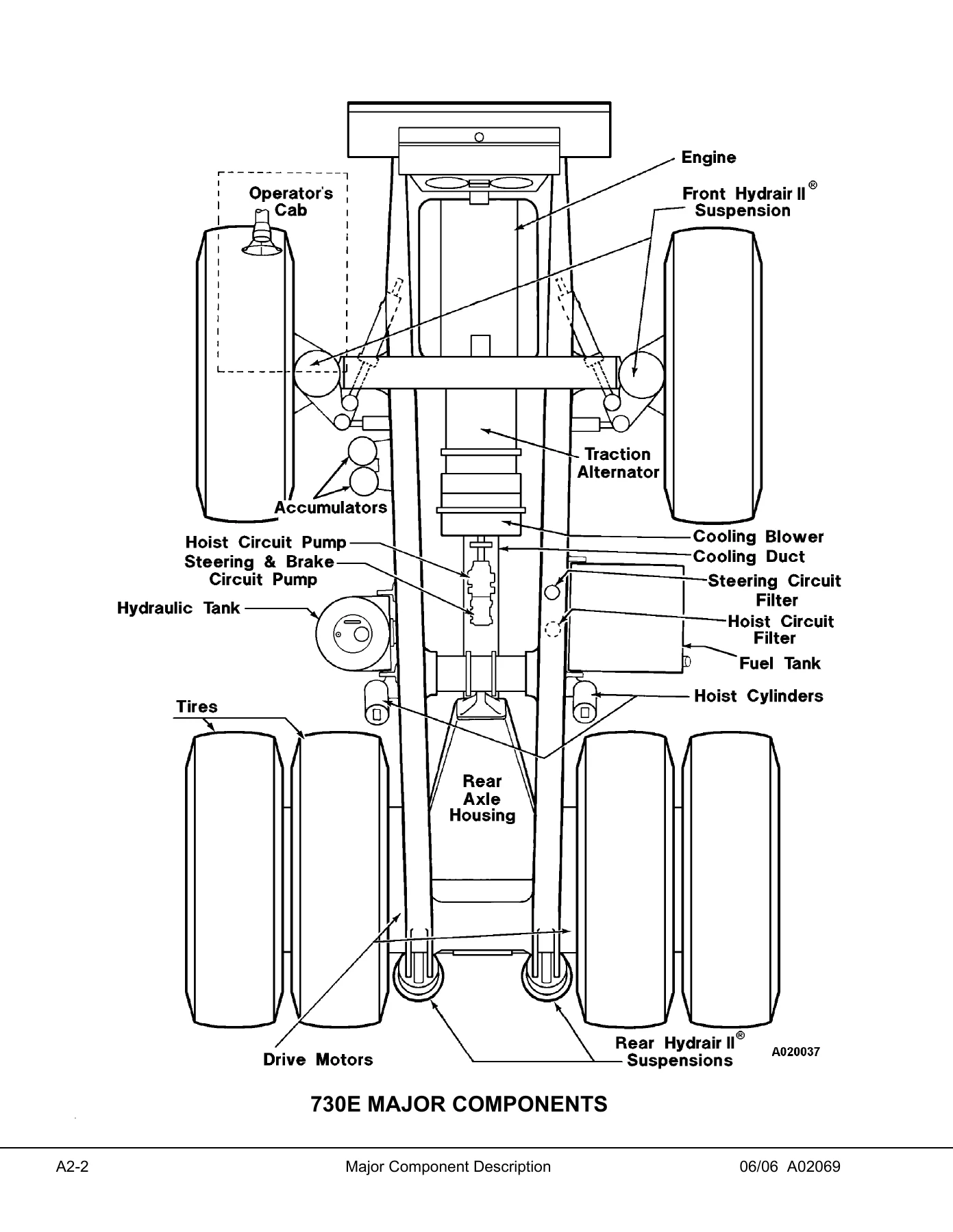
SECTION A2 – MAJOR COMPONENT DESCRIPTIONp. 11
SECTION A3 – GENERAL SAFETYp. 15
GENERAL SAFETY AND OPERATIONp. 17
PERSONAL SAFETYp. 17
Safety Rulesp. 17
Truck Safety Featuresp. 17
Clothing And Personal Itemsp. 17
Unauthorized Modificationp. 17
Leaving The Operator’s Seatp. 17
Mounting And Dismountingp. 18
Fire Extinguishers And First Aid Kitsp. 18
Precautions For High Temperature Fluidsp. 18
Asbestos Dust Hazard Preventionp. 19
Fire Prevention For Fuel And Oilp. 19
ROPS Precautionsp. 19
Preventing Injury From Work Equipmentp. 19
Precautions For Optional Attachmentsp. 19
Precautions When Starting The Machinep. 20
PRECAUTIONS FOR TRUCK OPERATIONp. 20
Safety Is Thinking Aheadp. 20
Safety At The Work Sitep. 20
Fire Preventionp. 20
Preparing For Operationp. 20
Ventilation For Enclosed Areasp. 20
Mirrors, Windows, And Lightsp. 21
In The Operator’s Cab – Before Starting The Enginep. 21
OPERATING THE MACHINEp. 21
Starting The Enginep. 21
Truck Operation – Generalp. 21
Traveling In The Truckp. 22
Precautions When Traveling In Reversep. 22
Traveling On Slopesp. 22
Ensuring Good Visibilityp. 23
Operating On Snowp. 23
Avoid Damage To The Dump Bodyp. 23
Driving Near High-Voltage Cablesp. 23
When Loading The Truckp. 23
When Dumpingp. 23
Working On Loose Groundp. 24
Parking The Machinep. 24
TOWINGp. 24
WORKING NEAR BATTERIESp. 24
Battery Hazard Preventionp. 24
Jump-Starting With Booster Cablesp. 25
PRECAUTIONS FOR MAINTENANCEp. 26
BEFORE PERFORMING MAINTENANCEp. 26
Stopping The Engine Before Servicep. 26
Warning Tagp. 26
Proper Toolsp. 26
Securing The Dump Bodyp. 26
DURING MAINTENANCEp. 27
Personnelp. 27
Attachmentsp. 27
Working Under The Machinep. 27
Keeping The Machine Cleanp. 27
Rules To Follow When Adding Fuel Or Oilp. 27
Radiator Coolant Levelp. 27
Use Of Lightingp. 28
Precautions With The Batteryp. 28
Handling High-Pressure Hosesp. 28
Precautions With High-Pressure Oilp. 28
Maintenance Near High Temperatures And High Pressuresp. 28
Rotating Fan And Beltsp. 28
Waste Materialsp. 28
TIRESp. 29
Handling Tiresp. 29
Tire Maintenancep. 29
Storing Tires After Removalp. 30
ADDITIONAL JOB SITE RULESp. 31
WHEN REPAIRS ARE NECESSARYp. 32
OPERATING INSTRUCTIONSp. 33
PREPARING FOR OPERATIONp. 33
SAFETY IS THINKING AHEADp. 33
WALK-AROUND INSPECTIONp. 33
ENGINE START-UPp. 37
AFTER ENGINE HAS STARTEDp. 38
MACHINE OPERATION SAFETY PRECAUTIONSp. 39
LOADINGp. 39
HAULINGp. 40
PASSINGp. 40
DUMPINGp. 40
To Raise The Dump Body:p. 41
To Lower The Dump Body: (When dumping over a berm or into a crusher):p. 41
To Lower The Dump Body (When dumping on flat ground):p. 42
TOWINGp. 42
SAFE PARKING PROCEDURESp. 43
ENGINE SHUTDOWN PROCEDUREp. 43
DELAYED ENGINE SHUTDOWN PROCEDUREp. 43
SUDDEN LOSS OF POWERp. 44
EMERGENCY STEERING SYSTEMp. 44
Operationp. 44
Testingp. 45
SECTION A4 – WARNINGS AND CAUTIONSp. 47
SECTION A5 -STANDARD TORQUE CHARTS AND CONVERSION TABLESp. 55
SECTION A7 – STORAGE AND IDLE MACHINE PREPARATION – INDEXp. 61
STORAGE AND IDLE MACHINE PREPARATIONp. 63
SHORT TERM IDLE PERIODSp. 63
PREPARATION FOR STORAGEp. 64
REMOVAL FROM STORAGEp. 65
RECONDITIONING AN IDLE VEHICLEp. 66
ENGINE OPERATIONp. 69
After The Engine Has Startedp. 69
ENGINE STORAGEp. 70
Temporary Storage (30 Days Or Less)p. 70
Extended Storage (More Than 30 Days)p. 71
RESTORING AN ENGINE AFTER EXTENDED STORAGEp. 72
ELECTRIC DRIVE TRUCKSp. 73
Storing A Truck That Is Operationalp. 73
Storing A Truck That Is Not Operationalp. 74
Storing A Major Componentp. 75
Periodic Inspectionsp. 75
Placing Equipment Into Service After Storagep. 75
SECTION B – STRUCTURES – INDEXp. 77
SECTION B2 – STRUCTURAL COMPONENTS – INDEXp. 79
STRUCTURAL COMPONENTSp. 81
LADDERSp. 81
Removalp. 81
Installationp. 81
GRILLE AND HOODp. 82
Removalp. 82
Installationp. 82
RIGHT-HAND DECKp. 82
Removalp. 82
Installationp. 84
CENTER DECKp. 84
LEFT-HAND DECKp. 85
Removalp. 85
Installationp. 85
SECTION B3 – DUMP BODY – INDEXp. 87
DUMP BODYp. 89
DUMP BODYp. 89
Removalp. 89
Installationp. 90
BODY SLINGp. 90
BODY PADSp. 91
Adjustmentp. 91
BODY GUIDEp. 92
BODY POSITION INDICATORp. 92
HOIST LIMIT SWITCHp. 92
ROCK EJECTORSp. 92
Inspectionp. 92
SECTION B4 – FUEL TANK – INDEXINDEXp. 93
FUEL TANKp. 95
Removalp. 95
Repairp. 95
Cleaningp. 95
Installationp. 96
FUEL GAUGE SENDERp. 97
Removalp. 97
Installationp. 97
LOW FUEL SENDERp. 98
Removalp. 98
Installationp. 98
FUEL RECEIVERp. 99
TANK BREATHER VALVEp. 100
Removalp. 100
Installationp. 100
Disassemblyp. 100
Assemblyp. 100
SECTION C – ENGINE – INDEXp. 101
SECTION C2 – POWER MODULE – INDEXp. 103
POWER MODULEp. 105
GENERAL INFORMATIONp. 105
POWER MODULE SERVICEp. 106
Removalp. 106
Installationp. 110
SECTION C3 – COOLING SYSTEM – INDEXp. 113
COOLING SYSTEMp. 115
RADIATORp. 115
Removalp. 115
Servicep. 116
Installationp. 116
RADIATOR FILL PROCEDUREp. 117
RADIATOR REPAIRp. 117
Internal Inspectionp. 117
External Cleaningp. 118
Disassemblyp. 118
Cleaning and Inspectionp. 119
Assemblyp. 119
Additional Service Informationp. 121
PRESSURE TESTINGp. 121
COOLANT SYSTEM TROUBLESHOOTINGp. 121
SECTION C4 – POWER TRAIN – INDEXp. 123
POWER TRAINp. 125
ALTERNATOR REMOVAL AND INSTALLATION PROCEDUREp. 125
General Informationp. 125
Removalp. 125
ALTERNATOR INSTALLATIONp. 127
Engine/Alternator Matingp. 127
Alternator Measurementp. 127
Engine End Play Measurementp. 128
Determining Shim Requirementsp. 129
Installing Alternator On Enginep. 130
ENGINEp. 131
Removalp. 131
Installationp. 131
SECTION C5 – AIR CLEANERS – INDEXp. 133
AIR CLEANERSp. 135
Service Checksp. 135
Filter Element Replacementp. 136
Main Filter Element Cleaningp. 138
Precleaner Sectionp. 139
Cleaning Precleaner Tubesp. 139
Air Intake Troubleshootingp. 140
SECTION C7 – FAN DRIVE CLUTCH – INDEXp. 141
FAN DRIVE CLUTCHp. 143
GENERAL DESCRIPTIONp. 143
COMPONENTSp. 143
Inputp. 143
Outputp. 143
Stationary Componentsp. 144
OPERATION MODESp. 145
Fully Engagedp. 145
Modulated Variable Speedp. 145
Fully Releasedp. 146
Remember:p. 146
Lubricating and Cooling Oilp. 147
MAINTENANCEp. 148
Maintenance Checks To Be Madep. 148
TROUBLESHOOTINGp. 149
Basic Preliminary Checksp. 149
FIELD CHECK DIAGNOSISp. 150
Preliminary Checks With Engine Offp. 150
Check Clutch Releasep. 150
Check Clutch Lock-upp. 151
Overheating Complaintp. 152
Thermal Sensor and Solenoid Valvep. 152
On Truck Testp. 152
Off Truck Testp. 153
Test Conditions and Requirements:p. 153
Test:p. 153
TROUBLESHOOTING CHARTp. 154
FAN CLUTCH DISASSEMBLY INSTRUCTIONSp. 157
REASSEMBLY OF THE FAN CLUTCHp. 164
INSPECTION OF PARTSp. 175
REBUILD TOOLSp. 178
SECTION D – ELECTRICAL SYSTEM – INDEXp. 181
SECTION D2 – 24 VDC ELECTRICAL SUPPLY SYSTEM – INDEXp. 183
24VDC ELECTRIC SUPPLY SYSTEMp. 185
ELECTRICAL SYSTEM DESCRIPTIONp. 185
BATTERIESp. 185
Maintenance and Servicep. 185
Troubleshootingp. 185
BATTERY CHARGING ALTERNATORp. 187
24VDC ELECTRIC START SYSTEMp. 187
CRANKING MOTORSp. 187
Removalp. 187
Installationp. 188
CRANKING MOTOR TROUBLESHOOTINGp. 188
Preliminary Inspectionp. 189
No-Load Testp. 189
Interpreting Results of Testsp. 189
Disassemblyp. 190
Cleaning and Inspectionp. 190
Armature Servicingp. 190
Field Coil Checksp. 193
Field Coil Removalp. 193
Solenoid Checksp. 193
Testp. 193
Assemblyp. 194
Pinion Clearancep. 195
MAGNETIC SWITCHp. 196
Coil Testp. 196
Electric Start System Wiring Diagramsp. 196
ENGINE PRELUB SYSTEMp. 196
OPERATIONp. 196
Pressure Switchp. 197
Suction Linep. 197
Outlet Linep. 197
Check Valvep. 197
Solenoid Timerp. 197
TROUBLESHOOTING PRELUB STARTER CIRCUITp. 199
SECTION D3 – 24VDC ELECTRICAL SYSTEM COMPONENTS – INDEXp. 203
24VDC ELECTRICAL SYSTEM COMPONENTSp. 205
PASSENGER SEAT BASE COMPARTMENTp. 205
COMPONENTSp. 205
Taillight Resistor Diode Assembliesp. 205
Inclinometerp. 205
Brake Warning Buzzer (BWB)p. 205
Lubrication System Timerp. 205
Five Minute Idle Timer Componentsp. 205
Five Minute Idle Timerp. 207
Five Minute Idle Relayp. 207
Five Minute Idle Contactorp. 207
Five Minute Idle Circuit Testp. 207
Data Store Switchp. 207
Komatsu Engine Quantum Connector (Not Used)p. 207
Komatsu Engine Cense Connectorp. 207
STATEX III Propulsion System Diagnostic Connectorp. 207
Spare Connector Locationp. 207
Alarm Indicating Device (AID) Systemp. 208
Diode Matrix (Without Sound)p. 208
Diode Matrix (With Sound)p. 209
Hot Switch Inverterp. 209
Hot Switch Inverter Card (Slot 4) (Not Used)p. 209
Temperaturep. 209
Oil Levelp. 209
Temperature and Latchp. 209
Coolant Level/Flasherp. 210
Lamp Testp. 210
BATTERY EQUALIZER BOXp. 210
Troubleshootingp. 210
BODY-UP SWITCHp. 211
Adjustmentp. 211
Servicep. 211
HOIST LIMIT SWITCHp. 212
Adjustmentp. 212
Servicep. 212
24-VOLT RELAY AND DIODE BOARDSp. 212
RELAY BOARDSp. 213
Descriptionp. 213
SERVICEp. 213
To Replace A Relay:p. 213
To Replace A Circuit Breaker:p. 213
To Replace A Circuit Panel Cardp. 214
Relay Board Componentsp. 214
Installing Additional Circuitsp. 215
DIODE BOARD 1p. 216
Diode Testingp. 216
CIRCUIT BREAKERSp. 218
SECTION D10 – BATTERY CHARGING ALTERNATOR – INDEXp. 219
BATTERY CHARGING SYSTEMp. 223
ELECTRICAL SYSTEM DESCRIPTIONp. 223
CHARGE VOLT AND AMP VALUESp. 223
BATTERYp. 223
Maintenance and Servicep. 223
Troubleshootingp. 224
Underchargingp. 224
Overchargingp. 224
Corrosionp. 224
Acid Levelsp. 224
Non-Use or Storagep. 224
Freezingp. 225
BATTERY CHARGING ALTERNATORp. 226
GENERAL INFORMATIONp. 226
General Descriptionp. 226
Terminal Identification and Locationp. 227
Battery Positive (B+)p. 227
Battery Negative (B-)p. 227
DC Output (D+)p. 227
AC Output (R)p. 227
Regulator Harness Plug Identificationp. 227
Alternator Specificationsp. 227
Performance Curvep. 227
Battery/Alternator Terminologyp. 228
WIRING DIAGRAMp. 230
DIMENSIONS AND TORQUE VALUESp. 231
PERIODIC MAINTENANCEp. 232
TESTINGp. 232
GENERAL INFORMATIONp. 232
Troubleshooting Alternator (On-Truck)p. 232
Equipment Requiredp. 232
Preliminary Checksp. 232
Test Set-upp. 234
Test Procedurep. 235
REGULATOR TESTINGp. 236
Regulator Bypass Test (No Output)p. 236
Regulator Bypass Test (Amp Rating)p. 237
BENCH TESTINGp. 238
Equipmentp. 238
Identification Recordp. 238
Advanced Troubleshootingp. 238
Bench Test 1: No-Load Testp. 238
Bench Test 2: Full Load Testp. 239
Bench Test 3: Regulator Bypass Testp. 239
STATIC TESTINGp. 240
Equipmentp. 240
Identification Recordp. 240
Regulator Testerp. 240
Check For Shorted Power Transistorp. 240
Circuit Testsp. 241
FIELD COIL TESTSp. 242
Field Coil Test 1: Check for Open or Shorted Field Coilp. 242
Field Coil Test 2: Check For Grounded Field Coilp. 242
STATOR TESTSp. 243
Stator Test 1: Check For Stator-To-Stator Continuityp. 243
Stator Test 2: Check For Grounded Statorsp. 244
THERMAL SWITCH TESTp. 244
Initial Testp. 244
Verifying a Faulty Thermal Switchp. 245
TROUBLESHOOTING TIPSp. 246
ALTERNATORp. 250
ALTERNATOR REPAIRp. 250
Removalp. 250
Installationp. 252
Special Tools and Lubricantsp. 252
Epoxy Adhesivep. 253
Liquid Threadlockersp. 253
Elastoplastic Silicone Resinp. 253
ALTERNATOR EXPLODED VIEWp. 256
ALTERNATOR DISASSEMBLYp. 258
Regulator Removalp. 258
Fan Removalp. 259
Pulley Removalp. 260
Anti-Drive End Housing Removalp. 260
Anti-Drive End Rotor Removalp. 262
Drive End Housing Removalp. 264
Drive End Rotor Removalp. 270
Field Coil Removalp. 271
Drive End and/or Anti-Drive End Stator Removalp. 273
CLEANING AND INSPECTIONp. 275
ALTERNATOR ASSEMBLYp. 275
Anti-Drive End Stator Installationp. 275
Drive End Stator Installationp. 277
Field Coil Installationp. 280
Drive End Bearing Installationp. 282
Drive End Rotor Installationp. 284
Rotor and Rotor Shaft Installationp. 284
Drive End Housing Installationp. 285
Anti-Drive End Rotor Installationp. 289
Anti-Drive End Housing Installationp. 290
Regulator Installationp. 293
THERMAL SWITCHp. 294
Removalp. 294
Installationp. 296
SUPPORT STANDp. 296
VEHICLE HEALTH MONITORING SYSTEM (VHMS)p. 299
VHMS BASIC FEATURESp. 299
Gather Datap. 299
Convert and Record Datap. 300
Communicate Data to Off-Board Systemsp. 300
USING THE VHMS SYSTEMp. 301
Basic Precautionsp. 301
Turning the VHMS System Onp. 301
Normal VHMS Operationp. 302
Turning the VHMS System Offp. 302
Downloading From the VHMS Controllerp. 302
VHMS DATA ITEMSp. 303
Fault Codesp. 303
Machine Historyp. 303
VHMS Historyp. 304
Snapshotsp. 304
Manual Snapshotsp. 304
Trendsp. 304
Histogram (Load Map) Datap. 306
Haul Cycle Datap. 307
Alarm and Snapshot Triggersp. 308
Satellite Featuresp. 310
VHMS DIAGNOSTIC FEATURESp. 310
Fault Historyp. 310
VHMS LED Digitsp. 310
Light (10) PLM III communicationp. 310
Light (11) OrbCommp. 310
VHMS COMPONENTSp. 311
VHMS CONTROLLERp. 311
Removalp. 312
Installationp. 312
OrbComm Controllerp. 313
Removalp. 313
Installationp. 314
INTERFACE MODULEp. 314
Inputsp. 315
Outputsp. 315
Removalp. 315
Installationp. 315
COMPONENT LOCATIONp. 316
Circuit Breakersp. 316
Temperature Sensorsp. 317
Pressure Sensorsp. 318
SECTION D11 – VHMS COMPONENTS – INDEXp. 297
VHMS SOFTWAREp. 321
Necessary Softwarep. 321
Necessary Toolsp. 322
VHMS TOOL BOX INSTALLATIONp. 322
VHMS SETTING TOOL INSTALLATIONp. 323
VHMS INITIALIZATION PROCEDUREp. 323
Preliminary Checksp. 323
Initialization Stepsp. 323
Select Operationp. 324
VHMS Setting Functionp. 324
Machine Information Setting(1)p. 324
Machine Information Setting(2)p. 324
Date and Time Settingp. 325
GCC Settingp. 325
Setting Summaryp. 325
VHMS SNAPSHOT PROCEDUREp. 326
VHMS DOWNLOADp. 326
VHMS FTP UPLOADp. 327
LOCATION OF DOWNLOAD FILESp. 328
INSTALLING FLASHBURN PROGRAMp. 329
INSTALLING APPLICATION CODE INTO INTERFACE MODULEp. 329
INSTALLING REALTIME MONITOR SOFTWARE PROGRAMp. 330
WHEN REPLACING A VHMS CONTROLLERp. 330
To Set: Date and time, satellite, payload meterp. 332
Review Setting Informationp. 334
SECTION D12 – VHMS SOFTWARE – INDEXp. 319
SECTION D13 – VHMS CHECKOUT AND TROUBLESHOOTING – INDEXp. 335
VHMS CHECKOUT AND TROUBLESHOOTINGp. 337
VHMS CHECKOUT PROCEDUREp. 337
Generalp. 337
Structure and Purposep. 338
Necessary Equipment:p. 338
VHMS SYSTEM CHECKOUTp. 338
Preliminaryp. 338
Checking Inputs To The Interface Modulep. 339
For 930E & 960E trucks only:p. 341
For 830E trucks only:p. 341
Checking Outputs From The Interface Modulep. 342
For 830E only:p. 342
For 930E & 960E only:p. 342
VHMS CONTROLLER CHECKOUTp. 342
TROUBLESHOOTINGp. 343
Communications Networksp. 343
Coaxial Cablep. 343
VHMS COMPONENTSp. 344
VHMS Controllerp. 344
OrbComm Controllerp. 345
Interface Modulep. 345
FAULT CODESp. 346
Fault Historyp. 346
VHMS LED Display Fault Codesp. 347
Chassis Fault Codesp. 348
Engine Fault Codesp. 352
FAULT TREE ANALYSISp. 358
Unable to connect to VHMS from laptop PCp. 358
Flashing Error Code N4-23 (PLM III Communications Fault)p. 359
Flashing Error Code N4-22 (Engine Communications Fault)p. 360
No Data Received By WebCAREp. 361
Coaxial Cable Troubleshootingp. 362
SECTION D14 – VHMS FORMS – INDEXp. 363
VHMS FORMSp. 365
VHMS INITIALIZATION CHECK LISTp. 365
VHMS DATA DOWNLOADp. 366
VHMS INITIALIZATION FORMp. 366
VHMS INITIALIZATION CHECK LISTp. 368
VHMS INITIALIZATION FORMp. 370
SECTION D35 – PAYLOAD METER III – INDEXp. 371
OPERATION SECTIONp. 377
Introductionp. 377
Data Summaryp. 377
Data Gatheringp. 377
COMPONENT DESCRIPTIONp. 378
System Diagramp. 378
Suspension Pressure Sensorsp. 378
Inclinometerp. 378
Operator Displayp. 378
Operator Switchp. 379
Speed Inputp. 379
Body-Up Switchp. 379
Brake Lock Switchp. 379
Payload Meterp. 379
Communications Portsp. 379
Key Switch Inputp. 380
Payload Meter Powerp. 380
Load Lightsp. 380
Wiring and Terminationp. 381
TCI Outputsp. 381
OPERATOR’S DISPLAY AND SWITCHp. 382
Reading the Speedometerp. 382
Reading the Load Displayp. 382
Using the Operator IDp. 382
Using the Load and Ton Counterp. 382
Total Ton Counterp. 382
Total Load Counterp. 383
Clearing the Countersp. 383
Viewing Live Sensor Datap. 383
Other Display Messagesp. 383
PAYLOAD OPERATION AND CALCULATIONp. 384
Description of Haul Cycle Statesp. 384
Haul Cycle Descriptionp. 384
Load Calculationp. 385
Carry Backp. 385
Measurement Accuracyp. 385
SOURCES FOR PAYLOAD ERRORp. 385
Payload Errorp. 385
Loading Conditionsp. 386
Pressure Sensorsp. 386
Swingloadsp. 386
Speed and Distancep. 386
HAUL CYCLE DATAp. 386
Haul Cycle Datap. 387
Haul Cycle Warning Flagsp. 388
Frame Torque Datap. 389
Sprung Weight Datap. 389
Maximum Speed Datap. 389
Alarm Recordsp. 389
Fault Code Datap. 390
PC SOFTWARE OVERVIEWp. 391
PC Overviewp. 391
System Configurationp. 391
Installing the PLMIII Softwarep. 391
DOWNLOADING DATAp. 392
PLM III SYSTEM CONFIGURATIONp. 393
Starting Communicationsp. 393
Displayed Payload Unitsp. 393
Time Unitsp. 393
Connection Menup. 393
Connecting to the Payload Meterp. 394
Configure the Payload Meterp. 394
Setting the Date and Timep. 394
Setting the Truck Typep. 395
Setting the Gauge Display Unitsp. 395
Setting the Frame Serial Numberp. 395
Setting the Truck Numberp. 395
Setting the Komatsu Distributorp. 395
Setting the Komatsu Customerp. 395
Clean Truck Tarep. 396
Inclinometer Calibrationp. 396
DATA ANALYSISp. 397
Creating a Queryp. 397
Sorting on Truck Unit Numberp. 397
Sorting on Truck Typep. 397
Sorting on Date Rangep. 398
Sorting on Time Rangep. 398
Payload Detail Screenp. 399
Creating Reportsp. 399
Summary – One Page Reportp. 400
Detailed – Multi-Page Reportp. 400
Creating Graphsp. 401
Exporting Datap. 401
CSV Exportp. 401
Compressedp. 403
Importing Datap. 403
Deleting Haul Cycle Recordsp. 403
Viewing Alarmsp. 404
Deleting Alarm Recordsp. 404
TROUBLESHOOTING SECTIONp. 405
TROUBLESHOOTINGp. 405
Viewing Active Alarmsp. 405
Real-Time Data Displayp. 405
Testing the Payload Lightsp. 406
Creating Log Files of Inputsp. 406
Daily Inspectionsp. 406
Periodic Maintenancep. 406
Abnormal Displays at Power-Upp. 407
No Payload Display When Key Switch is Turned Onp. 408
No Display on Speedometerp. 409
No Display on Operator Displayp. 409
No Communications With PCp. 410
Load Lights Don’t Light During Loadingp. 411
Load Lights Remain Onp. 412
Load Lights Remain On During Dumpingp. 412
Display Doesn't Clear When The Load Is Dumpedp. 412
Calibration Problemsp. 413
Alarm 1 – Left-Front Pressure Highp. 414
Alarm 2 – Left-Front Pressure Lowp. 414
Troubleshoot Wiring to Left-Front Suspensionp. 414
Alarm 3 – Right-Front Pressure Highp. 415
Alarm 4 – Right-Front Pressure Lowp. 415
Troubleshoot Wiring to Right-Front Suspensionp. 415
Alarm 5 – Left-Rear Pressure Highp. 416
Alarm 6 – Left-Rear Pressure Lowp. 416
Troubleshoot Wiring to Left-Rear Suspensionp. 416
Alarm 7 – Right-Rear Pressure Highp. 417
Alarm 8 – Right-Rear Pressure Lowp. 417
Troubleshoot Wiring to Right-Rear Suspensionp. 417
Alarm 9 – Inclinometer Highp. 418
Alarm 10 – Inclinometer Lowp. 418
Troubleshoot Inclinometer Wiringp. 418
Alarm 13 – Body-Up Input Failurep. 419
Alarm 16 – Memory Write Failurep. 420
Alarm 17 – Memory Read Failurep. 420
Alarm 18p. 421
Alarm 19p. 421
Alarm 22p. 421
Operator Switch Doesn't Workp. 422
Alarm 26 – User Switch Fault – SELECTp. 422
Alarm 27 – User Switch Fault – SETp. 422
Connector Mapp. 423
Connectorsp. 424
PLMIII CHECKOUT PROCEDUREp. 425
General Descriptionp. 425
Tools Requiredp. 425
Checkout Procedurep. 425
PLMIII CHECKOUT PROCEDURE CONFIRMATIONp. 429
Flashburn Programmingp. 429
Confirmation Checklistp. 431
SECTION E – ELECTRICAL PROPULSION COMPONENTS – INDEXp. 433
SECTION E2 – ELECTRICAL PROPULSION COMPONENTS – INDEXp. 435
ELECTRICAL PROPULSION COMPONENTSp. 439
GENERAL SYSTEM DESCRIPTIONp. 439
CONTROL SYSTEMp. 439
System Operationp. 440
FL275 Panelp. 441
CARD REPLACEMENTp. 442
Removalp. 442
Installationp. 442
Card Repairp. 442
Panel Wiringp. 442
COMPUTER DESCRIPTIONp. 443
Microprocessorp. 443
Download Capabilityp. 443
SOFTWAREp. 443
Base Monitor Programp. 443
Runtime Monitor Program – OBJ Running Codep. 443
Configuration Software – CFGp. 444
PTU – Portable Test Unit Codep. 444
System Regulationp. 444
Propulsionp. 445
Retardingp. 445
TWO-DIGIT DISPLAY PANELp. 446
The Coded Numberp. 446
Eventsp. 446
Framesp. 447
Windowsp. 447
System Categoriesp. 447
Limits On Resetting Faultsp. 447
NA Faultsp. 448
Event Sequencep. 448
Resetting Eventsp. 448
Event Descriptionsp. 448
Subcode Descriptionsp. 448
2-DIGIT DISPLAY PANEL SUBCODESp. 456
PORTABLE TEST UNIT (PTU)p. 459
DESCRIPTIONp. 459
Operational Hintsp. 459
SOFTWARE INSTALLATION PREPARATIONp. 460
HARD DISK SPACE REQUIREMENTSp. 460
SOFTWARE INSTALLATION ON PTUp. 460
PTU/Truck Communication Problemsp. 461
THE MAIN MENUp. 462
Quit Menup. 462
PTU Talk To Truckp. 462
View PTU Saved Filesp. 462
List Stat Data Filesp. 462
Truck Setup (CFG)p. 462
Select Truck Setupp. 462
Update CFG Versionp. 462
Change PTU Passwordp. 462
CONFIGURATION (CFG) FILE CONVERSIONp. 464
Conversion Procedurep. 464
Convert Old CFG files for New softwarep. 465
STATEX CONFIGURATION FILESp. 468
0) Source Directory: . . .p. 468
1) Select A Truck Configuration . . .p. 469
2) View Truck Configuration: Data Curves . . .p. 470
3) Change/View Serial and Model Numbers . . .p. 471
4) View Options . . .p. 471
5) Change/View Truck Specifics . . .p. 473
6) Change/View Overspeeds . . .p. 475
7) Save a Truck Configuration, filename: . . .p. 476
8) Save Directory: . . .p. 477
CHANGE PTU PASSWORDp. 478
PROGRAMMING THE TRUCKp. 479
Connect PTU to the Truckp. 479
Select Configuration Filep. 479
Activate The PTU Modep. 479
Check Object Code Versionp. 480
Download Configuration Filesp. 481
Date And Timep. 482
Event Datap. 483
Statistical Datap. 485
View Countersp. 485
View Profilesp. 485
Upload Statistical Data To A Filep. 485
Statistical Data Codes – Countersp. 486
STATISTICAL DATA CODES – COUNTERSp. 487
STATISTICAL DATA CODES – PROFILESp. 492
TRUCK SPECIFIC INFORMATIONp. 496
Temporary Truck Settingsp. 497
MISCELLANEOUS FEATURESp. 498
Saving Datap. 498
PTU Abbreviationsp. 499
Other Menu Selectionsp. 499
MISCELLANEOUS ELECTRICAL PROPULSION COMPONENTSp. 500
ALTERNATORp. 500
ELECTRIC WHEEL MOTORSp. 500
RETARDING GRIDSp. 500
ELECTRONIC ACCELERATOR AND RETARD PEDALSp. 500
Removalp. 500
Installationp. 500
Disassemblyp. 501
Reassemblyp. 501
COOLING BLOWER WARNING SYSTEMp. 501
Operationp. 501
Testp. 501
Removalp. 502
Installationp. 502
ELECTRICAL CONTROL CABINETp. 503
ABBREVIATIONS FOR STATEX III ELECTRIC DRIVE COMPONENTSp. 508
CARD IDENTIFICATION LIST 17FL275 PANEL, STATEX IIIp. 509
SECTION E3 – STATEX III ELECTRICAL SYSTEM CHECKOUT PROCEDURE – INDEXp. 511
STATEX III ELECTRICAL SYSTEM CHECKOUT PROCEDUREp. 515
GENERAL INFORMATIONp. 515
COMMUNICATIONS PORT CHECKp. 516
PTU Hookupp. 516
4.0 SEQUENCE TESTS – (ENGINE NOT ON)p. 517
Preparation and Setupp. 517
CONTROL SYSTEM SELF-TESTp. 518
4.1 THROTTLE SYSTEM CHECK AND ADJUSTMENTp. 518
4.2 RETARD SYSTEM CHECK AND ADJUSTMENTp. 519
PTU Setupp. 519
4.3 REVERSER AND PROPULSION CONTACTORS CHECKp. 520
4.4 NOT USED.p. 521
4.5 RETARD CONTACTORS OPERATION CHECKp. 521
4.6 GROUND FAULT SENSING CHECKp. 521
4.7 GROUND FAULT IN RETARD OPERATION CHECKp. 522
4.8 OVERRIDE OPERATION CHECKp. 522
4.9 ANTI-REVERSAL FUNCTION (AR) CHECKp. 523
4.10 OVERSPEED RETARD OPERATION CHECKp. 523
4.11 HOIST INTERLOCK OPERATION CHECKp. 524
4.12 MOTOR BLOWER FAULT LIGHT OPERATION CHECKp. 524
Return to Main Menup. 524
5.0 DIGITAL INPUT/OUTPUT SIGNALS TEST – FL275 CARD PANELp. 525
5.1 SETUP MANUAL DIGITAL INPUT/OUTPUT TEST ON PTUp. 525
5.2 DIGITAL INPUT CHECKSp. 526
5.3 DIGITAL OUTPUT CHECKSp. 527
6.0 ANALOG INPUT SIGNALS TEST – FL275 CARD PANELp. 531
6.1 SETUP ANALOG INPUT MONITOR SCREEN ON PTUp. 531
6.2 ANALOG INPUT CHECKSp. 532
6.3 FREQUENCY INPUT CHECKSp. 536
Return to Main Menup. 537
7.0 SPEED EVENT CHECKSp. 537
Preparation and Setupp. 537
Setup PTUp. 537
7.1 SINGLE SPEED OVERSPEED TRUCK – OVERSPEED SETTINGS CHECKp. 538
7.2 TWO SPEED OVERSPEED TRUCK (EMPTY TRUCK) – OVERSPEED SETTINGS CHECKp. 538
7.3 TWO SPEED OVERSPEED TRUCK (LOADED TRUCK) – OVERSPEED SETTINGS CHECKp. 538
7.4 OTHER SPEED EVENTS CHECKSp. 538
Return to Main Menup. 538
8.0 RETARD SPEED CONTROL SYSTEM CHECKp. 539
Preparation and Setupp. 539
Setup PTUp. 539
8.1 OVERSPEED PICKUP AND DROPOUT CHECKp. 539
8.2 RETARD POT MAXIMUM SETTING CHECKp. 539
8.3 RETARD POT MINIMUM SETTING CHECKp. 539
8.4 ACCELERATOR PEDAL OVERRIDE OF RETARD SPEED CONTROLp. 540
Return to Main Menup. 540
9.0 LOAD TEST USING TRUCK RETARD GRIDSp. 540
Setup and Preparationp. 540
PTU Setupp. 540
9.1 LOAD TESTp. 541
10.0 MOTOR FIELD CURRENT CHECK IN RETARDINGp. 541
Setup PTUp. 541
10.1 RETARD CHECKp. 542
11.0 MISCELLANEOUS COMPONENT TEST AND ADJUSTMENTp. 543
11.1 BRAKE SYSTEM INTERLOCKS CHECKp. 543
Preparationp. 543
11.2 BLOWER LOSS PRESSURE SWITCH ADJUSTMENTp. 543
11.3 SYNC TRANSFORMER CHECKOUTp. 544
11.4 POWER CONTACTOR POSITION SENSOR ADJUSTMENTp. 544
11.5 BATTERY BOOST ADJUSTMENTp. 544
11.6 ISOLATION AMPLIFIER AND VOLTAGE MODULE TESTp. 544
11.7 MOTOR ROTATION TESTp. 545
11.8 GROUND FAULT CHECKSp. 545
12.0 MISCELLANEOUS CHARTSp. 546
12.1 WHEEL MOTOR GEAR RATIOSp. 546
12.2 MAXIMUM ALLOWABLE TRUCK SPEEDSp. 547
12.3 ENGINE OPTIONSp. 548
SECTION G – DRIVE AXLE, SPINDLE AND WHEELS – INDEXp. 549
SECTION G2 – TIRES AND RIMS – INDEXp. 551
TIRES AND RIMSp. 553
GENERAL INFORMATIONp. 553
TIRESp. 553
Handling Tiresp. 553
Tire Maintenancep. 554
Storing Tires After Removalp. 554
FRONT TIRES AND RIMSp. 555
Removalp. 555
Installationp. 556
REAR TIRES AND RIMSp. 557
Removalp. 557
Installationp. 558
RIMp. 559
Tire Removalp. 559
RIM AND TIRE PREPARATIONp. 560
LUBRICANTSp. 560
TIRE INSTALLATIONp. 561
SECTION G3 – FRONT WHEEL HUB AND SPINDLE – INDEXp. 563
FRONT WHEEL HUB AND SPINDLEp. 565
WHEEL HUB AND SPINDLE ASSEMBLYp. 565
Removalp. 565
Installationp. 567
Disassemblyp. 568
Cleaning and Inspectionp. 569
Assemblyp. 569
Wheel Bearing Adjustment (Spindle Vertical)p. 572
Wheel Bearing Adjustment (Tire Mounted)p. 573
STEERING CYLINDERS AND TIE RODp. 574
Spherical Bearing Wear Limitsp. 574
Removalp. 575
Installationp. 577
Bearing Replacementp. 577
TOE-IN ADJUSTMENTp. 578
SECTION G4 – REAR AXLE HOUSING – INDEXp. 579
REAR AXLE HOUSINGp. 581
PIVOT PINp. 581
Removalp. 581
Installationp. 582
PIVOT EYE BEARINGp. 582
Disassemblyp. 582
Assemblyp. 583
PIVOT EYE REPAIRp. 583
Removalp. 583
Disassemblyp. 583
Bushing (New)p. 583
Pivot Eye Bore (New)p. 583
Assemblyp. 583
Installationp. 584
ANTI-SWAY BARp. 584
Removalp. 584
Installationp. 584
Disassemblyp. 585
Cleaning and Inspectionp. 585
Assemblyp. 585
SECTION G5 – REAR AXLE HOUSING – INDEXp. 587
REAR AXLE HOUSINGp. 589
Removalp. 589
Installationp. 589
WHEEL MOTORp. 589
Removalp. 589
Cleaning and Inspectionp. 590
Installationp. 590
Maximum Cap Screw Usagep. 590
REAR AXLE HOUSING BUMPER PADp. 591
SECTION H – SUSPENSIONS – INDEXp. 593
SECTION H2 – FRONT SUSPENSION – INDEXp. 595
FRONT SUSPENSIONp. 597
Removalp. 597
Installationp. 599
Turn-of-the-Nut Tightening Procedurep. 600
Disassemblyp. 601
Cleaning and Inspectionp. 602
Assembly (Bearing Only)p. 602
Suspension Assembly (Complete)p. 602
SUSPENSION PRESSURE TESTp. 604
SECTION H3 – REAR SUSPENSIONS – INDEXp. 607
REAR SUSPENSIONSp. 609
Removalp. 610
Installationp. 612
Disassemblyp. 612
Cleaning and Inspectionp. 612
Assemblyp. 613
SUSPENSION PRESSURE TESTp. 615
SECTION H4 – OILING AND CHARGING PROCEDURES – INDEXp. 617
OILING AND CHARGING PROCEDUREp. 619
GENERALp. 619
EQUIPMENT LISTp. 619
Hydrair® Charging Kitp. 619
Installation of Charging Kitp. 619
Removal of Charging Kitp. 620
Support Blocks For Oiling and Charging Dimensionsp. 620
FRONT SUSPENSIONp. 621
Front Suspension Oilingp. 621
Front Suspension Nitrogen Chargingp. 622
REAR SUSPENSIONp. 624
Rear Suspension Oilingp. 624
Rear Suspension Nitrogen Chargingp. 626
OIL AND NITROGEN SPECIFICATIONS CHARTp. 627
SECTION J – BRAKE CIRCUIT – INDEXp. 629
SECTION J2 – BRAKE CIRCUIT – INDEXp. 631
BRAKE CIRCUITp. 633
GENERAL DESCRIPTIONp. 633
SERVICE BRAKE CIRCUITp. 633
SECONDARY BRAKING AND AUTOMATIC APPLYp. 635
PARKING BRAKE CIRCUITp. 635
Normal Operation (key switch on, engine on)p. 635
BRAKE LOCK CIRCUITp. 636
WARNING CIRCUITp. 636
SECTION J3 – BRAKE CIRCUIT COMPONENT SERVICE – INDEXp. 639
BRAKE CIRCUIT COMPONENT SERVICEp. 641
BRAKE VALVEp. 641
Rebuild Criteriap. 641
Removalp. 641
Installationp. 643
Disassemblyp. 645
Cleaning and Inspectionp. 647
ASSEMBLYp. 647
Actuator Base Threaded Insertsp. 647
Boot and Capp. 647
Valve Body Seal Installationp. 648
Regulator Sleeve O-Ring Installationp. 649
Actuator Plunger O-Ring Installationp. 649
Assembly of Valvep. 649
DIFFERENTIAL PRESSURE SWITCHp. 650
Disassemblyp. 651
Cleaning and Inspectionp. 651
Assemblyp. 651
VALVE BENCH TEST AND ADJUSTMENTp. 651
Test Set Up Procedurep. 653
Brake Valve Output Pressure Adjustmentp. 653
Differential Pressure Switch Testp. 654
Final Test and Adjustmentp. 654
Installation Of Brake Pedal Actuator Assembly to Brake Valvep. 655
BRAKE ASSEMBLIES WITH INTEGRAL MOUNTED ELECTRONIC RETARD PEDAL (DUAL FUNCTION PEDAL)p. 657
Installation of Retard Pedal To Brake Pedalp. 657
HYDRAULIC BRAKE ACCUMULATORSp. 658
Brake Accumulator Bleed-Down Procedurep. 658
Removalp. 658
Installationp. 660
Disassemblyp. 660
Cleaning and Inspectionp. 662
Assemblyp. 662
Leak Testingp. 664
BRAKE ACCUMULATOR CHARGINGp. 665
Temperature During Prechargep. 667
ACCUMULATOR STORAGEp. 668
Installationp. 668
BRAKE CIRCUIT CHECK-OUT PROCEDUREp. 671
SECTION J4 – BRAKE CIRCUIT CHECK-OUT PROCEDURE – INDEXp. 671
BRAKE CIRCUIT CHECK-OUT PROCEDUREp. 673
EQUIPMENT REQUIREDp. 676
INITIAL SYSTEM SET-UPp. 677
Parking Brakep. 677
Service Brakesp. 678
Brake Lock/Secondaryp. 678
Low Brake Pressure and Auto Applyp. 679
Reapplicationsp. 679
Differential Pressure Switchp. 679
BRAKE CIRCUIT AND BRAKE VALVE TROUBLESHOOTINGp. 681
CHECK-OUT PROCEDUREp. 684
HYDRAULIC BRAKE SYSTEM DATA SHEETp. 684
SECTION J5 – FRONT DISC BRAKES- INDEXp. 687
FRONT DISC BRAKESp. 689
BRAKE CALIPERp. 689
Removalp. 689
Installationp. 690
Disassemblyp. 691
Cleaning and Inspectionp. 691
Assemblyp. 693
BRAKE LININGp. 693
Replacementp. 693
FRONT SERVICE BRAKE BURNISHINGp. 695
BRAKE BLEEDING PROCEDUREp. 696
REAR DISC BRAKESp. 699
REAR BRAKESp. 699
CALIPER, DISC, AND PARKING BRAKEp. 699
Removalp. 699
Installationp. 700
Trucks equipped with one-piece adapterp. 703
Removalp. 703
Installationp. 704
CALIPER PISTONp. 705
Piston Assembly Removalp. 705
Inspectionp. 705
Piston Assembly Installationp. 706
FUNCTIONAL TEST OF PISTON ASSEMBLYp. 707
Return Spring Forcep. 707
Built-In Clearancep. 707
Grip Forcep. 708
Grip Force Measurementp. 710
Spring Force Measurementp. 711
Disassembly of Piston Assemblyp. 712
Assembly of Piston Assemblyp. 713
BENCH TESTp. 713
BRAKE LININGp. 714
Replacementp. 714
SERVICE BRAKE BURNISHINGp. 717
SAFETY PRECAUTIONSp. 717
Rear Brake Conditioningp. 718
BRAKE BLEEDING PROCEDUREp. 719
Spring Force Measurementp. 720
SECTION J6 – REAR BRAKES – INDEXp. 697
SECTION J7 – PARKING BRAKE – INDEXp. 721
PARKING BRAKEp. 723
GENERAL INFORMATIONp. 723
PARKING BRAKE CALIPERp. 723
Lining Thickness Inspectionp. 723
Removalp. 724
Installationp. 724
Parking Brake Adjustmentp. 725
Parking Brake Caliper Disassemblyp. 726
Cleaning and Inspectionp. 727
Parking Brake Caliper Assemblyp. 728
PARKING BRAKE LINING REPLACEMENTp. 728
PARKING BRAKE BURNISH PROCEDUREp. 728
Lining Conditioningp. 728
BRAKE BLEEDING PROCEDUREp. 729
HYDRAULIC SYSTEMp. 731
SECTION L – HYDRAULIC SYSTEM – INDEXp. 731
SECTION L2 – HYDRAULIC SYSTEM – INDEXp. 733
HYDRAULIC SYSTEMp. 735
GENERAL INFORMATIONp. 735
HYDRAULIC SYSTEMS OPERATIONp. 735
Hoist Circuit Operationp. 735
Steering Circuit Operationp. 737
SECTION L3 – HYDRAULIC SYSTEM COMPONENT REPAIR – INDEXp. 741
HYDRAULIC SYSTEM COMPONENT REPAIRp. 743
HOIST PUMPp. 743
Removalp. 743
Installationp. 744
Disassemblyp. 745
Inspection of Partsp. 748
Assemblyp. 748
Troubleshooting Guidep. 752
HYDRAULIC TANKp. 753
Filling Instructionsp. 753
Removalp. 754
Installationp. 754
HYDRAULIC TANK STRAINER AND DIFFUSERp. 754
Removalp. 754
Inspect and Cleanp. 755
Installationp. 755
SECTION L4 – STEERING CIRCUIT – INDEXp. 757
STEERING CIRCUITp. 759
STEERING CIRCUIT OPERATIONp. 759
COMPONENT DESCRIPTIONp. 760
Steering Control Valvep. 760
Unloader Valvep. 761
Bleed-Down Manifold Valvep. 761
Flow Amplifierp. 767
FLOW AMPLIFIER SYSTEM OPERATIONp. 768
No Steerp. 768
Steering Leftp. 770
Steering Rightp. 772
No Steer, External Shock Loadp. 774
Steering Pumpp. 776
High Pressure Filterp. 776
Accumulatorsp. 776
Low Precharge Warning Switchp. 776
SECTION L5 – STEERING CONTROL UNIT – INDEXp. 777
STEERING CONTROL UNITp. 779
GENERAL INFORMATIONp. 779
Removalp. 779
Installationp. 779
STEERING CONTROL UNIT REBUILDp. 781
Disassemblyp. 781
Cleaning and Inspectionp. 782
Assemblyp. 784
STEERING/BRAKE PUMPp. 787
Removalp. 787
Installationp. 787
Disassemblyp. 789
Inspection of Partsp. 790
Assemblyp. 790
SECTION L6 – STEERING CIRCUIT COMPONENT REPAIR – INDEXp. 793
STEERING CIRCUIT COMPONENT REPAIRp. 795
BLEED-DOWN MANIFOLDp. 795
Removalp. 795
Installationp. 795
ACCUMULATORp. 796
Removalp. 796
Installationp. 797
Disassemblyp. 798
Cleaning and Inspectionp. 798
Assemblyp. 798
Leak Testingp. 799
STEERING ACCUMULATOR CHARGINGp. 801
Temperature During Prechargep. 804
ACCUMULATOR STORAGEp. 804
Installationp. 805
FLOW AMPLIFIERp. 806
Removalp. 806
Installationp. 806
Disassemblyp. 806
Assemblyp. 809
STEERING CYLINDERSp. 810
Disassemblyp. 810
Piston Seal and Bearing Installationp. 810
Cylinder Assemblyp. 810
Testp. 811
TROUBLESHOOTING CHARTp. 813
SECTION L7 – HOIST CIRCUIT – INDEXp. 817
HOIST CIRCUITp. 819
HOIST CIRCUIT OPERATIONp. 819
COMPONENT DESCRIPTIONp. 820
Hydraulic Tankp. 820
Hydraulic Pumpp. 820
High Pressure Filterp. 820
Hoist Valvep. 820
Hoist Pilot Valvep. 821
Bleed-Down Manifoldp. 822
Counterbalance Manifoldp. 822
Hoist-Up Limit Solenoidp. 822
Pilot Operated Check Valvep. 822
HOIST VALVE OPERATIONp. 823
Float Operationp. 823
Power Up Operation (Figure 7-5)p. 825
Hold Operation (Figure 7-6)p. 827
Power Down Operation (Figure 7-7)p. 829
Float Operation (Figure 7-8)p. 831
SECTION L8 – HOIST CIRCUIT COMPONENT REPAIR – INDEXp. 833
HOIST CIRCUIT COMPONENT REPAIRp. 835
HOIST VALVEp. 835
Removalp. 835
Installationp. 835
O-Ring Replacementp. 837
INLET SECTIONp. 838
Disassemblyp. 838
Cleaning and Inspectionp. 839
Assemblyp. 839
REAR SPOOL SECTION (WORK PORTS)p. 840
Disassemblyp. 840
Cleaning and Inspectionp. 842
Assemblyp. 842
HOIST PILOT VALVEp. 844
Removalp. 844
Installationp. 844
Disassemblyp. 845
Cleaning and Inspectionp. 846
Assemblyp. 846
HOIST UP LIMIT SOLENOID VALVEp. 847
HOIST CYLINDERSp. 847
Removalp. 847
Installationp. 848
Disassemblyp. 851
Cleaning and Inspectionp. 852
SS1143 Tightening Tool – Assembly Drawingp. 853
ASSEMBLY OF QUILL AND CYLINDERp. 853
Quill Installationp. 853
Installation Of Check Balls And Plugs In Quillp. 854
Assembly of Cylinderp. 856
COUNTERBALANCE MANIFOLDp. 857
SECTION L9 – HIGH PRESSURE FILTERS – INDEXp. 859
HYDRAULIC SYSTEM FILTERSp. 861
HOIST CIRCUIT FILTERp. 861
Filter Element Replacementp. 861
Removalp. 862
Installationp. 862
Indicator Switchp. 862
STEERING CIRCUIT FILTERp. 863
Filter Element Replacementp. 863
Removalp. 864
Installationp. 864
Indicator Switchp. 864
INDICATOR SWITCHp. 864
Test Procedurep. 864
SECTION L10 – HYDRAULIC CHECK-OUT PROCEDURE – INDEXp. 867
HYDRAULIC CHECK-OUT PROCEDUREp. 869
INITIAL START UP AND FLUSHINGp. 869
COMPONENT CHECKOUT AND ADJUSTMENTp. 871
ADJUSTMENT PROCEDURE FOR HOIST COUNTERBALANCE CARTRIDGE VALVEp. 873
Counterbalance Valve Adjustmentp. 875
Manifold Assemblyp. 875
OIL CLEANLINESS CHECKp. 875
Oil Sampling Location On Truckp. 875
Oil Sampling Process and Cleanliness Criteriap. 876
DISABLED TRUCK DUMPING PROCEDUREp. 876
Hookupp. 876
Raising the Bodyp. 876
Lowering the Bodyp. 877
Troubleshooting Chartp. 878
SECTION M – OPTIONS AND SPECIAL TOOLS – INDEXp. 885
SECTION M7 – ENGINE OIL HEATERS – INDEXp. 887
ENGINE OIL HEATERSp. 889
GENERAL INFORMATIONp. 889
TROUBLESHOOTINGp. 889
HEATER ELEMENTp. 889
Removalp. 889
Installationp. 890
SECTION M8 – SPECIAL TOOLSp. 891
SECTION N – OPERATOR'S CAB – INDEXp. 901
SECTION N2 – TRUCK CAB – INDEXp. 903
TRUCK CABp. 905
TRUCK CABp. 905
Descriptionp. 905
Removalp. 906
Installationp. 908
CAB DOORp. 908
Removalp. 908
Installationp. 909
Door Adjustmentp. 909
Door Jam Bolt Adjustmentp. 909
Door Handle Plunger Adjustmentp. 911
Replace Door Glassp. 912
Replace Door Window Regulatorp. 916
Replace Door Handle or Latch Assemblyp. 916
Door and Door Hinge Seal Replacementp. 917
Door Opening Seal Removalp. 917
Installationp. 917
GLASS REPLACEMENTp. 918
Adhesive-Bonded Windowsp. 918
Recommended Tools/Suppliesp. 918
Replacement Procedurep. 918
Windshield and Rear Glassp. 919
Removalp. 919
Installationp. 920
SECTION N3 – CAB COMPONENTS – INDEXp. 921
CAB COMPONENTSp. 923
WINDSHIELD WIPERSp. 923
WIPER MOTOR REPLACEMENTp. 923
Removalp. 923
Installationp. 923
WIPER ARM REPLACEMENTp. 923
Removalp. 923
Installationp. 924
WIPER LINKAGE REPLACEMENTp. 924
Removalp. 924
Installationp. 925
WINDSHIELD WASHERp. 925
Operationp. 925
Servicep. 925
SECTION N4 – OPERATOR COMFORT – INDEXp. 927
HEATER/AIR CONDITIONERp. 929
CONTROLSp. 929
Operationp. 929
Heater/Air Conditioner Ventsp. 929
Defroster Vent Control Switchp. 929
Heat Control Switchp. 929
Temperature Control Knobp. 929
Fan Control Knobp. 929
Heater/Air Conditioner Selector Switchp. 929
COMPONENTSp. 930
Circuit Breakersp. 930
Relaysp. 930
Heater Corep. 930
Fan Motor and Speed Controlp. 931
Testp. 931
Actuatorsp. 931
Testp. 931
Cab Air Filterp. 932
AIR CONDITIONING SYSTEMp. 934
AIR CONDITIONING FOR OFF-HIGHWAY VEHICLESp. 935
PRINCIPLES OF REFRIGERATIONp. 935
Air Conditioningp. 935
Refrigeration – The Act of Coolingp. 936
The Refrigeration Cyclep. 936
AIR CONDITIONER SYSTEM COMPONENTSp. 937
Compressor (Refrigerant Pump)p. 937
Service Valvesp. 937
Receiver-Drierp. 937
Condenserp. 937
Expansion Block Valvep. 938
Accumulatorp. 938
Evaporatorp. 939
ELECTRICAL CIRCUITp. 939
Thermostatp. 939
Compressor Clutchp. 940
Trinary™ Switchp. 940
SYSTEM SERVICINGp. 942
SERVICE TOOLS AND EQUIPMENTp. 943
Recovery/Recycle Stationp. 943
Leak Detectorp. 944
Service Valvesp. 944
Vacuum Pumpp. 944
Manifold Gauge Setp. 945
Low Side Gaugep. 945
High Side Gaugep. 945
Installing Manifold Gauge Setp. 946
Purging Air From Service Hosesp. 946
SYSTEM PERFORMANCE TESTp. 947
SYSTEM OILp. 948
Handling and Reusing RPAG Oilp. 948
Oil Quantityp. 948
Checking System Oilp. 948
REFRIGERANTp. 949
Recycled Refrigerantp. 949
Reclaimed Refrigerantp. 949
Refrigerant Quantityp. 950
R-134a Refrigerant Containersp. 950
SYSTEM LEAK TESTINGp. 950
Electronic Leak Detectorp. 951
Tracer Dyesp. 951
Soap and Waterp. 951
RECOVERING AND RECYCLING THE REFRIGERANTp. 952
Performing the Recovery Cyclep. 952
Performing the Recycling Procedurep. 952
Evacuating and Charging the A/C Systemp. 952
SYSTEM REPAIRp. 953
System Flushingp. 953
COMPONENT REPLACEMENTp. 954
Hoses and Fittingsp. 954
Linesp. 954
Expansion Valvep. 954
Receiver-Drierp. 954
Thermostatp. 954
Compressorp. 955
Accumulatorp. 955
Clutchp. 955
Servicing the Compressor Clutchp. 956
Pulley Removalp. 958
Clutch Coil Checkp. 959
Pulley Installationp. 959
Clutch Assembly Installationp. 960
EVACUATING THE SYSTEMp. 961
CHARGING THE A/C SYSTEMp. 963
AIR CONDITIONER DRIVE BELTp. 964
Pulley Alignmentp. 964
Belt Tensionp. 965
TROUBLESHOOTINGp. 966
Preliminary Checksp. 966
Diagnosis of Gauge Readings and System Performancep. 966
TROUBLESHOOTING BY MANIFOLD GAUGE SET READINGSp. 967
PREVENTATIVE MAINTENANCE SCHEDULE FOR A/C SYSTEMp. 973
SECTION N5 – OPERATOR CONTROLS AND EQUIPMENT – INDEXp. 975
OPERATOR CONTROLS AND EQUIPMENTp. 977
STEERING WHEEL AND CONTROLSp. 978
STEERING WHEELp. 978
HORN BUTTONp. 978
TILT/TELESCOPE LEVERp. 978
M ULTI-FUNCTION TURN SIGNAL SWITCHp. 978
Turn Signal Operationp. 978
High Beam Headlight Operationp. 979
Windshield Wiper Operationp. 979
STEERING COLUMNp. 979
Removalp. 979
Inspectionp. 980
Installationp. 980
PEDALSp. 980
SERVICE BRAKE PEDALp. 980
DYNAMIC RETARDER PEDALp. 980
Optional – Dual Function/Single Pedalp. 981
THROTTLE PEDALp. 981
OVERHEAD PANEL CONTROLS AND COMPONENTSp. 982
GRADE/SPEED WARNING CHARTp. 982
RADIO SPEAKERSp. 982
WARNING ALARM BUZZERp. 982
CAB RADIOp. 982
WARNING LIGHTS DIMMER CONTROLp. 982
WARNING/STATUS INDICATOR LIGHT PANELp. 982
AIR CLEANER VACUUM GAUGESp. 982
WINDSHIELD WIPERSp. 982
TRUCK CONTROLSp. 983
F-N-R Selector Switchp. 983
Hoist Control Leverp. 984
CONSOLE SWITCHES AND CONTROLSp. 984
Ashtrayp. 984
Cigarette Lighterp. 984
Left-Hand Window Control Switchp. 984
Right-Hand Window Control Switchp. 984
Engine Shutdown Switchp. 984
Override Switchp. 984
Retard Speed Control (RSC) Switchp. 985
Retard Speed Control (RSC) Dialp. 985
Statex III Download Portp. 985
Engine Diagnostic Port (CENSE)p. 986
Modular Mining Portp. 986
Passenger Seatp. 986
Engine Diagnostic Connectorsp. 986
Engine Diagnostics Connectorp. 986
Data Storage Buttonp. 986
PAYLOAD METERp. 986
Payload Meter Download Connectorp. 986
CAB CLIMATE CONTROLp. 987
HEATER/AIR CONDITIONER VENTSp. 987
HEATER/AIR CONDITIONER CONTROLS AND VENTSp. 987
Defroster Vent Control Switchp. 987
Heat Control Switchp. 987
Temperature Control Knobp. 987
Fan Control Knobp. 987
Heater/Air Conditioner Ventsp. 987
OPERATOR SEATp. 988
ADJUSTMENTp. 988
INSTRUMENT PANELp. 989
CONTROL SYMBOLSp. 989
CONTROL SWITCHES AND GAUGESp. 990
Key Switchp. 991
Engine Shutdown Switch With Timer Delayp. 991
Fog Light Switchp. 991
Ladder Light Switchp. 991
Backup Light Switchp. 991
Panel Illumination Lightsp. 991
Cab Air Conditioner/Heater Ventsp. 991
Engine Cold Weather Starting Aid Switchp. 992
Rotating Beacon Light Switchp. 992
Heated Mirror Switchp. 992
Wheel Brake Lock Switchp. 992
Parking Brake Switchp. 992
Digital Tachometerp. 993
Right Turn Signal Indicator Lightp. 993
High Beam Headlight Indicator Lightp. 993
Left Turn Signal Indicator Lightp. 993
Digital Speedometer/Payload Meter Displayp. 993
Voltmeter Gaugep. 993
Engine Oil Pressure Gaugep. 993
Engine Water Temperature Gaugep. 993
Fuel Gaugep. 994
Engine Hourmeterp. 994
Headlight Switchp. 994
Panel Illumination Lights Dimmer Rheostatp. 994
Payload Meter Switchp. 994
OVERHEAD STATUS/WARNING INDICATOR LIGHT PANELp. 995
DESCRIPTION OF INDICATOR SYMBOLSp. 995
INDICATOR LIGHT FUNCTIONSp. 996
High Hydraulic Oil Temperaturep. 996
Low Steering Pressurep. 996
Low Accumulator Precharge Pressure Warningp. 996
Electric System Fault Warningp. 997
Low Brake Pressure Indicatorp. 997
Low Hydraulic Tank Levelp. 997
Low Automatic Lubrication System Pressurep. 997
Circuit Breaker Trippedp. 997
Hydraulic Oil Filterp. 997
Low Fuel Indicatorp. 998
Parking Brake Indicatorp. 998
Service Brake Indicatorp. 998
Body Up Indicatorp. 998
Dynamic Retarding Indicatorp. 998
Stop Engine Warningp. 998
Backup Indicatorp. 998
Engine Shutdown Timer Switch- Five Minute Idlep. 998
Retard Speed Controlp. 999
Service Engine Indicator (AEM)p. 999
High Wheel Motor Temperature Indicatorp. 999
Blower Fault Warningp. 999
Service Engine Indicator (CENSE)p. 999
Komatsu Engines w/Centry™ Fuel Controlp. 999
Hazard Warning Light Switchp. 1000
Lamp Test Switch/Centry™ Diagnostic Test Switchp. 1000
CENTRY™ FUEL SYSTEM DIAGNOSTICSp. 1000
GENERAL OPERATIONp. 1000
DETERMINING FAULT CODESp. 1000
EXITING THE DIAGNOSTICS MODEp. 1002
VEHICLE HEALTH MONITORING SYSTEM (VHMS)p. 1002
BASIC PRECAUTIONSp. 1002
OPERATIONp. 1002
INTERFACE MODULEp. 1004
SECTION P – LUBRICATION AND SERVICE – INDEXp. 1005
SECTION P2 – LUBRICATION AND SERVICE – INDEXp. 1007
LUBRICATION AND SERVICEp. 1009
GENERAL INFORMATIONp. 1009
HYDRAULIC TANK SERVICEp. 1009
Adding Oilp. 1009
COOLING SYSTEMp. 1010
Coolant Level Checkp. 1010
Radiator Filling Procedurep. 1010
Antifreeze Temperature Recommendationsp. 1010
50 HOUR LUBRICATION AND MAINTENANCE CHECKSp. 1014
100 HOUR LUBRICATION AND MAINTENANCE CHECKSp. 1014
250 HOUR LUBRICATION AND MAINTENANCE CHECKSp. 1015
500 HOUR LUBRICATION AND MAINTENANCE CHECKSp. 1018
1000 HOUR LUBRICATION AND MAINTENANCE CHECKSp. 1020
1500 HOUR LUBRICATION AND MAINTENANCE CHECKSp. 1021
2500 HOUR LUBRICATION AND MAINTENANCE CHECKSp. 1022
5000 HOUR LUBRICATION AND MAINTENANCE CHECKSp. 1023
10,000 HOUR LUBRICATION AND MAINTENANCE CHECKSp. 1023
SECTION P3 – AUTOMATIC LUBRICATION SYSTEM – INDEXp. 1025
AUTOMATIC LUBRICATION SYSTEMp. 1027
GENERAL DESCRIPTIONp. 1027
SYSTEM COMPONENTSp. 1028
Filter Assemblyp. 1028
Hydraulic Motor and Grease Pumpp. 1028
Reservoirp. 1029
Fixed Pressure Reducing Valvep. 1029
Flow Control Valvep. 1029
Solenoid Valvep. 1029
Vent Valvep. 1029
24VDC Lubrication Cycle Timerp. 1029
Time Delay Modulep. 1029
Pump Cutoff Pressure Switchp. 1029
Unloader Valvep. 1029
Pressure Switchp. 1029
Pressure Gaugep. 1031
Manual Override Buttonp. 1031
Injectorsp. 1031
SYSTEM OPERATIONp. 1033
Normal Operationp. 1033
Pressure Failure Detection Circuitsp. 1034
GENERAL INSTRUCTIONSp. 1035
LUBRICANT REQUIRED FOR SYSTEMp. 1035
SYSTEM PRIMINGp. 1035
LUBRICANT PUMPp. 1036
Pump Housing Oil Levelp. 1036
Pump Pressure Controlp. 1036
FILTER AND RESERVOIRp. 1036
Filter Assembly Elementp. 1037
INJECTORS (SL-1 Series H)p. 1037
Injector Specificationsp. 1037
Injector Adjustmentp. 1037
INJECTOR OPERATIONp. 1039
SYSTEM CHECKOUTp. 1040
Lubrication Cycle Timer Checkp. 1040
Lubrication Cycle Timer Adjustmentp. 1041
PREVENTIVE MAINTENANCE INSPECTIONp. 1041
10 Hour Lubrication System Inspectionp. 1041
100 Hour Inspectionp. 1041
250 Hour Inspectionp. 1041
500 Hour Inspectionp. 1042
1000 Hour Inspectionp. 1042
PUMP REBUILDp. 1043
Disassemblyp. 1043
Cleaning and Inspectionp. 1044
Assemblyp. 1046
VENT VALVE REB UILDp. 1047
Disassembly and Assemblyp. 1047
SYSTEM TROUBLESHOOTING CHARTp. 1048
SECTION P4 – MOTORIZED WHEEL MAINTENANCE SCHEDULE – INDEXp. 1051
MOTORIZED WHEEL MAINTENANCE SCHEDULEp. 1053
AXLE BOXp. 1053
MOTORIZED WHEEL MAINTENANCE SCHEDULEp. 1054
ARMATURE AREAp. 1054
AT TIRE CHANGEp. 1054
MOTORIZED WHEEL MAINTENANCE SCHEDULEp. 1055
GENERATOR/ALTERNATORp. 1055
GRID BLOWER MOTORp. 1055
CONTROL EQUIPMENT CHECKSp. 1055
MOTORIZED WHEEL MAINTENANCE SCHEDULEp. 1056
VEHICLE OPERATIONS TESTSp. 1056
SECTION R – SYSTEM SCHEMATICS – INDEXp. 1057
HYDRAULIC BRAKE SYSTEM SCHEMATIC – EF5755p. 1059
HYDRAULIC SYSTEM SCHEMATIC – EJ2729p. 1060
ELECTRICAL SCHEMATIC – XS0100p. 1061
VHMS SYSTEM SCHEMATIC – EL8720p. 1094

This Komatsu 730E Dump Truck Shop Manual is not a general overview. It is a complete service and repair reference covering every major system on the truck — from the engine and cooling system through the electric propulsion and control system, the hydraulic system, brakes, suspensions, drive axle, and operator’s cab. Each section provides step-by-step removal, disassembly, inspection, assembly, and installation instructions, along with specifications, torque values, wear limits, and troubleshooting guidance. The electrical schematics section alone spans 33 sheets, giving a technician the wiring detail needed to trace circuits, diagnose faults, and repair the electrical system correctly.

What This Manual Enables You to Do

With the Komatsu 730E Shop Manual CEBM018000 in hand, a service technician can perform the full range of repairs and maintenance on the 730E dump truck. That includes engine removal and installation, cooling system service, alternator and wheel motor service, hydraulic pump and valve repair, brake caliper and disc service, suspension removal and charging, hoist cylinder repair, steering system diagnosis, and complete electrical troubleshooting through the Statex III control system. The manual also covers the Vehicle Health Monitoring System (VHMS), Payload Meter III, and the automatic lubrication system — all critical to keeping the truck productive and reliable.

Correct procedures and specifications matter on a machine this size. Using the wrong torque value, missing a wear limit, or skipping a critical adjustment can lead to component failure, downtime, or unsafe operation. This manual provides the exact figures and sequences the manufacturer specifies, so the work is done right the first time.

IMAGES PREVIEW

Komatsu 730E Dump Truck Shop Manual - CEBM018000 Complete Service & Repair PDF — PDF page 1 preview
Komatsu 730E Dump Truck Shop Manual - CEBM018000 Complete Service & Repair PDF — PDF page 12 preview
Komatsu 730E Dump Truck Shop Manual - CEBM018000 Complete Service & Repair PDF — PDF page 14 preview

Instant PDF Delivery — No Shipping, No Waiting

This Komatsu 730E Dump Truck Shop Manual is delivered as an instant PDF download after payment. There is no physical book to ship, no waiting for delivery, and no risk of a damaged or lost manual. You can access the file immediately on any device — laptop, tablet, or smartphone — and print the pages you need for the shop floor. Keep it on a USB drive, store it on a shop computer, or print a complete bound copy for the service truck. The PDF format means you can zoom in on detailed illustrations, wiring diagrams, and exploded views for a closer look at every component.
Reviews

There are no reviews yet.

Be the first to review “Komatsu 730E Dump Truck Shop Manual – CEBM018000 Complete Service & Repair PDF”

What Our Customers Say

★★★★★ Live reviews from customers
Loading customer reviews...
0
    0
    Your Cart
    Your cart is emptyReturn to Shop
    🛒
    Recently Purchased
    🕒 verified order