
Komatsu D475A-3 Crawler Dozer Shop Manual – SEBM017208 PDF Download
Original price was: $39.95.$24.95Current price is: $24.95.
Complete Komatsu D475A-3 shop manual (SEBM017208) covering serial numbers 10601 and up. Full engine, power train, transmission, steering, final drive, hydraulics, and electrical service procedures in one downloadable PDF.
Description
Komatsu D475A-3 Shop Manual – SEBM017208
This is the full Komatsu D475A-3 shop manual, published under document number SEBM017208 and covering machine serial numbers 10601 and up. It is the same technical reference used in a service workshop to diagnose, test, adjust, disassemble, assemble, and repair the D475A-3 crawler dozer. Every chapter is structured the way a technician works: understand the structure and function first, verify with testing and adjusting, then perform disassembly and assembly to maintenance standard tolerances.
The D475A-3 mounts the SDA12V140-1 engine, and the manual notes that engine details are covered in the separate 12V140-1 Series Engine Shop Manual. Within this document you get the chassis-side coverage: engine mount and damper, torque converter and PTO, TORQFLOW transmission, steering clutch and brake, transfer and bevel gear, final drive, track frame, idler, recoil spring, track roller bogie, track roller, carrier roller, track shoe, equalizer bar, pivot shaft, hydraulic pump, main control valves, PPC valve, work equipment cylinders, blade, and ripper equipment.
File Details
- Manual type: Shop Manual (Service / Repair)
- Brand: Komatsu
- Model: D475A-3 Crawler Dozer
- Document number: SEBM017208
- Serial number coverage: 10601 and up
- Engine reference: SDA12V140-1 (see separate 12V140-1 Series Engine Shop Manual)
- Language: English
- File format: PDF
- Page count: Approximately 970 pages
Chapters Covered
The manual is divided into six top-level chapters, each further split into component groups.
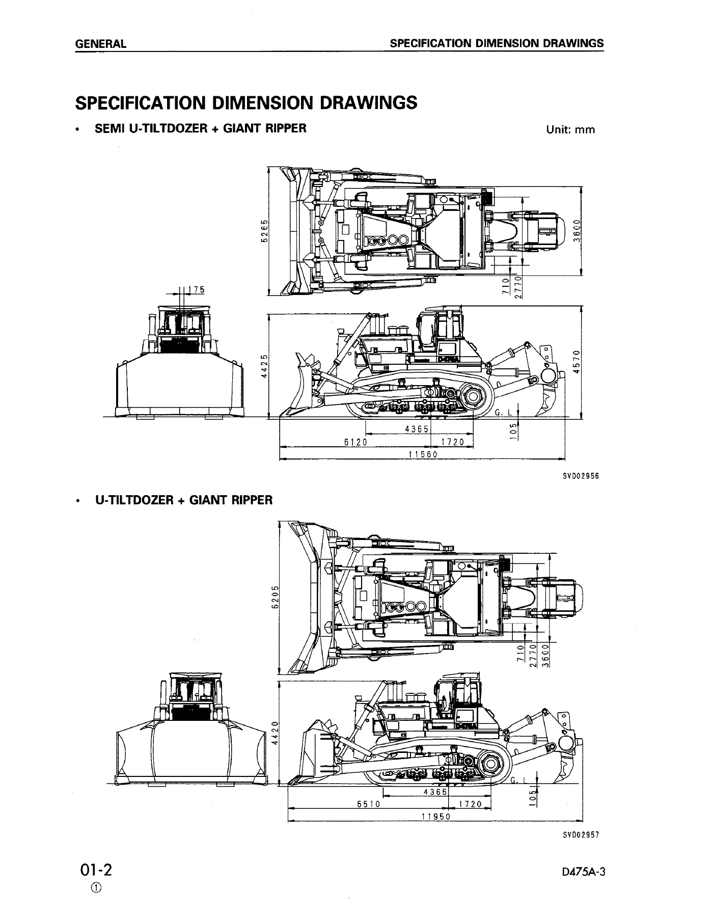
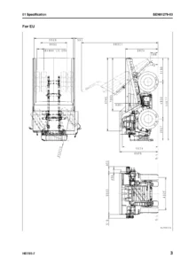
- 01 GENERAL – Specification dimension drawings, Specifications, Weight table, Table of fuel, coolant and lubricants
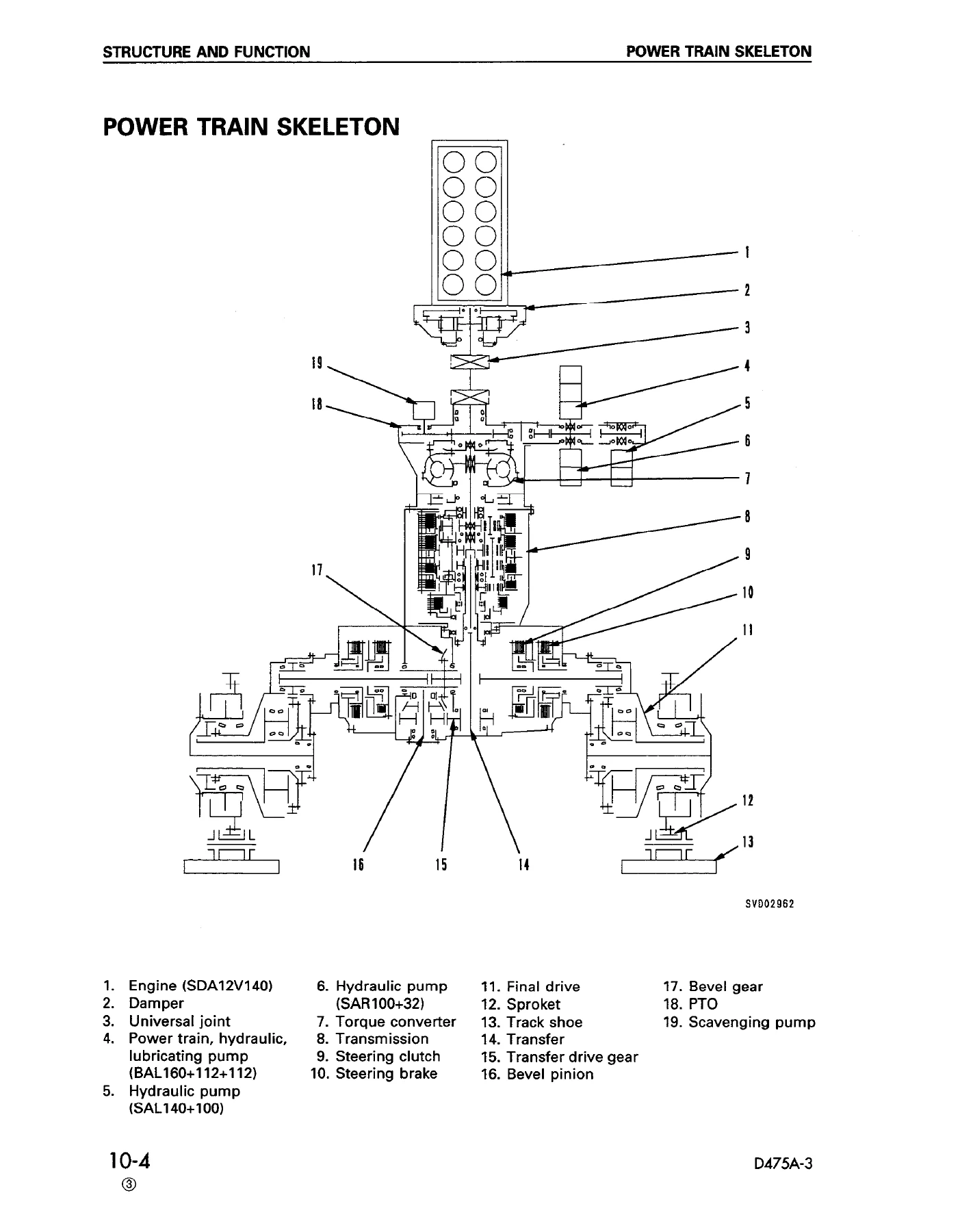
- 10 STRUCTURE AND FUNCTION – Engine and power train cooling system drawing, Power train, Power train skeleton, Power train hydraulic piping diagram, Power train hydraulic circuit diagram, Torque converter and PTO, Torque converter valve, Transmission, Transmission control valve, Steering and brake control, Transfer / bevel gear shaft / steering, Transfer and bevel pinion, Steering control valve, Final drive, Track frame, Track roller bogie, Hydraulic tank, PPC valve, Main control valve, Pin-puller hydraulic system and circuit, Pin-puller solenoid valve, Air conditioner, Engine control, Engine control system with electronic engine throttle controller, Machine monitor system, Mode selection system, Electrical equipment, Torque converter lock-up control system
- 20 TESTING AND ADJUSTING – Standard value tables for engine, chassis, and electrical related parts, plus step-by-step testing and adjusting procedures for engine speed, boost pressure, exhaust temperature, exhaust color, valve clearance, compression pressure, blow-by pressure, engine oil pressure, fuel injection timing, belt tensions, engine speed sensor, fuel control dial and decelerator pedal, torque converter stall, power train oil pressure, brake performance, full monolever and parking lever, brake pedal linkage, idler clearance, track shoe tension, work equipment oil pressure, work equipment control circuit pressure, PPC valve and pitch/tilt control valve output pressure, PPC valve adjustment, demand solenoid output pressure, ripper pin-puller solenoid output pressure, hydraulic drift, internal cylinder leakage, pressure release, air bleeding, safety lever, model selection, and blade tilt limit angle
- 30 DISASSEMBLY AND ASSEMBLY – Engine oil cooler, Fuel injection pump, Aftercooler core, Nozzle holder, Engine front seal, Engine rear seal, Cylinder head, Fuel tank, Main radiator, Sub radiator, Radiator guard, Engine, Damper, Power train unit, PTO and torque converter, Torque converter, PTO, TORQFLOW transmission, Steering case, Steering clutch and brake, Transfer gear housing, Power train pump, Scavenging pump, Torque converter oil cooler, Torque converter valve, Transmission control valve, Steering control valve, Final drive, Track frame, Idler, Recoil spring, Track roller, Carrier roller, Bogie, No. 1 bogie, Track shoe, Pivot shaft, Equalizer bar, Equalizer bar bushing, Hydraulic pump, Blade lift valve, Blade tilt and ripper Lo valve, Ripper Hi valve, PPC relief valve, Hydraulic cylinder, Ripper pin-puller cylinder, Blade, Giant ripper, ROPS guard, Operator’s cab, Floor frame, Dashboard, Controller, Air conditioner compressor, Air conditioner condenser, Air conditioner unit, Hood
- 40 MAINTENANCE STANDARD – Wear limits, clearances, tolerances, and repair limits for engine mount, damper, universal joint, torque converter, torque converter valve, TORQFLOW transmission, transmission control valve, power train / hydraulic / lubrication pump, transfer and bevel pinion, bevel gear shaft, steering clutch and brake, steering control valve, final drive, main frame, track frame, recoil spring, idler, track roller bogie, track roller, carrier roller, track shoe, equalizer bar, pivot shaft, hydraulic pump, work equipment control pump, main control valve, PPC valve, work equipment cylinder, cylinder stay, blade, and ripper equipment
- 90 OTHERS – Work equipment hydraulic circuit diagrams (single tilt, dual tilt tandem, dual tilt parallel, super dozer), Chassis electrical circuit diagrams (single tilt, dual tilt, super dozer, heavy-duty), Electrical circuit diagram inside cab
What This Komatsu D475A-3 Shop Manual Gives You
This is not a general bulldozer book with a few D475A-3 pages dropped in. Every procedure, every tolerance table, and every circuit diagram is written around the D475A-3. That matters because the machine sits at the top of the Komatsu dozer line and its systems do not behave like a smaller machine’s. The steering clutch and brake, the TORQFLOW transmission, the torque converter lock-up and stator clutch, the hydraulically balanced blade lift circuit with demand valve, the ripper Hi valve, and the dual tilt and super dozer pitch circuits each have their own service logic. The manual treats each one separately.
When you open the Testing and Adjusting chapter you are not reading generic advice. You get the actual standard value tables for the SDA12V140-1 engine: high idling 2,100 – 2,200 rpm, low idling 600 – 700 rpm, rated speed 2,000 rpm, boost pressure minimum 120 kPa at rated output, exhaust temperature limit 650 degrees Celsius, valve clearance 0.43 mm intake and 0.80 mm exhaust, compression pressure minimum 3.63 MPa, oil pressure 0.39 – 0.54 MPa at high idling. Below those tables sit the field procedures: how to bleed the oil from the boost gauge hose, how to use the peak mode on the digital temperature gauge, how to re-enact a service code, and how to release the remaining pressure in the hydraulic circuit before opening a line.
The power train chapter alone justifies the manual. Torque converter stall speed, full stall speed, main relief pressure, modulating pressure, reducing pressure, lubrication pressure, left and right steering clutch and brake pressures – all of it is measured with the joystick in specific positions, and the manual tells you exactly which positions. The torque converter valve section walks through the main relief valve, the torque converter relief valve, the lock-up selector valve, the lock-up solenoid valve, the stator clutch modulating valve, and the lock-up clutch modulating valve, with set pressures for each.
For a machine running a lock-up clutch, the section on torque converter lock-up control is critical reading. Lock-up comes on when the torque converter output shaft reaches 1,360 rpm and the transmission oil pressure is at or above 1.95 MPa, and drops out when speed falls to 1,330 rpm or pressure falls to 1.5 MPa. Getting that behaviour wrong shortens torque converter life and wastes fuel. The manual shows the oil flow in both the converter drive and direct drive states, and explains why the stator clutch must release when lock-up engages.
In the Disassembly and Assembly chapter you get removal and installation plus full disassembly and assembly for major components, with lifting weights printed for parts that need a hoist. That includes the counterweight, the power train unit at 5,500 kg, the final drive at 3,600 kg, the track frame at 11,050 kg, the TORQFLOW transmission at 1,400 kg, the PTO and torque converter assembly at 850 kg, the radiator guard at 4,700 kg, the ripper beam at 2,450 kg, and the operator’s cab at 150 kg. Special tool lists and sketches are provided so you can see which Komatsu tools are used and where a locally made jig will do the job.
The Maintenance Standard chapter is where a workshop lives day to day. It lists standard size, tolerance, standard clearance, and repair limit for the parts that wear – clutch discs and plates, seal rings, bushings, bearings, gear backlash, spring free lengths, press-fitting forces. When you are deciding whether a steering clutch disc or a final drive floating seal goes back in or gets replaced, this is the table you open.
Practical Repairs This Manual Supports
- Diagnosing low drawbar pull, slow travel, or a machine that will not move in one or more gear ranges
- Measuring and adjusting transmission main relief, modulating, reducing, and lubrication pressures
- Servicing the torque converter lock-up and stator clutch circuits
- Replacing steering clutch and brake discs, checking oil pressures, and adjusting the full monolever and parking lever
- Rebuilding the final drive – backlash, preload, floating seal installation, and sprocket tooth wear limits
- Track frame, idler, recoil spring, track roller bogie, carrier roller, and track shoe service including link press-fit dimensions and one-link field repair
- Blade lift, tilt, pitch, and ripper hydraulic troubleshooting including hydraulic drift diagnosis and internal cylinder leakage measurement
- Reading and using the chassis and inside-cab electrical circuit diagrams for the single tilt, dual tilt, super dozer, and heavy-duty specifications
- Working through machine monitor and controller service codes using the N, E, C, H, and M mode troubleshooting sections
Why the Correct Komatsu D475A-3 Data Matters
Big dozers are unforgiving of guesswork. A steering clutch set to the wrong pressure will slip and burn. A final drive preload set by feel will fail within a shift. A track tension set to the wrong sag will eat the sprocket or throw a link. This manual gives you the printed values – standard clearance, repair limit, tightening torque, set pressure – and the order in which the checks are done. That turns a repair from a trial-and-error job into a procedure you can finish and sign off.
IMAGES PREVIEW
Instant PDF Delivery
The Komatsu D475A-3 shop manual arrives as a downloadable PDF the moment your order completes. No shipping, no waiting, no customs. Read it on a laptop in the workshop office, open it on a tablet next to the machine, or print the pages you need and take them into the pit. Keep it on file for the life of the dozer – serial numbers 10601 and up are all covered.

Reviews
There are no reviews yet.