
Komatsu HD785-5 HD985-5 Dump Truck Shop Manual – PDF Repair Guide
Original price was: $46.95.$28.95Current price is: $28.95.
Complete Komatsu shop manual for the HD785-5 and HD985-5 rigid dump trucks (SA12V140-1 engine), covering structure and function, testing and adjusting, disassembly and assembly, and maintenance standards across 1,332 pages.
Description
Komatsu HD785-5 and HD985-5 Shop Manual
This is the full Komatsu shop manual for the HD785-5 and HD985-5 rigid dump trucks, issued under document number SEBM013912. It applies to HD785-5 machines from serial number 4001 and up, and to HD985-5 machines from serial number 1021 and up. Both models mount the Komatsu SA12V140-1 engine; while this manual covers the truck chassis and its major systems in depth, engine internals are handled in the separate 12V140-1 Series Engine Shop Manual.
File Details
- Manual type: Shop Manual (workshop repair and service)
- Brand: Komatsu
- Models covered: HD785-5, HD985-5
- Serial numbers: HD785-5 4001 and up; HD985-5 1021 and up
- Engine: Komatsu SA12V140-1 (12V140-1 series)
- Language: English
- Page count: 1,332
- File format: PDF
- Document number: SEBM013912
Chapters Covered
The manual follows Komatsu’s standard six-part shop manual structure, with every section indexed and cross-referenced so a technician can move from a symptom to the correct procedure quickly.
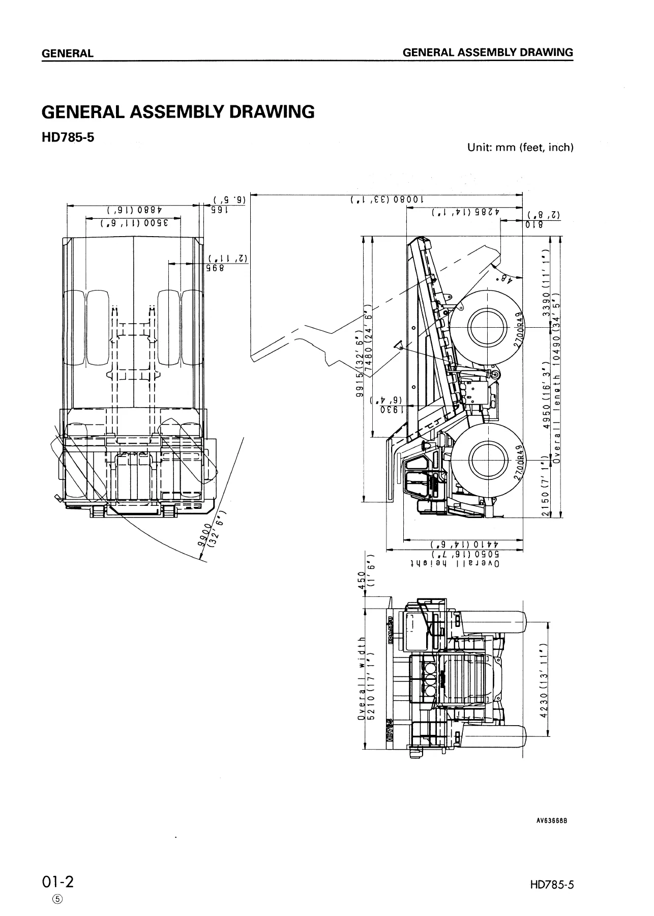
- 01 GENERAL — general assembly drawing, specifications, weight table, list of lubricant and water
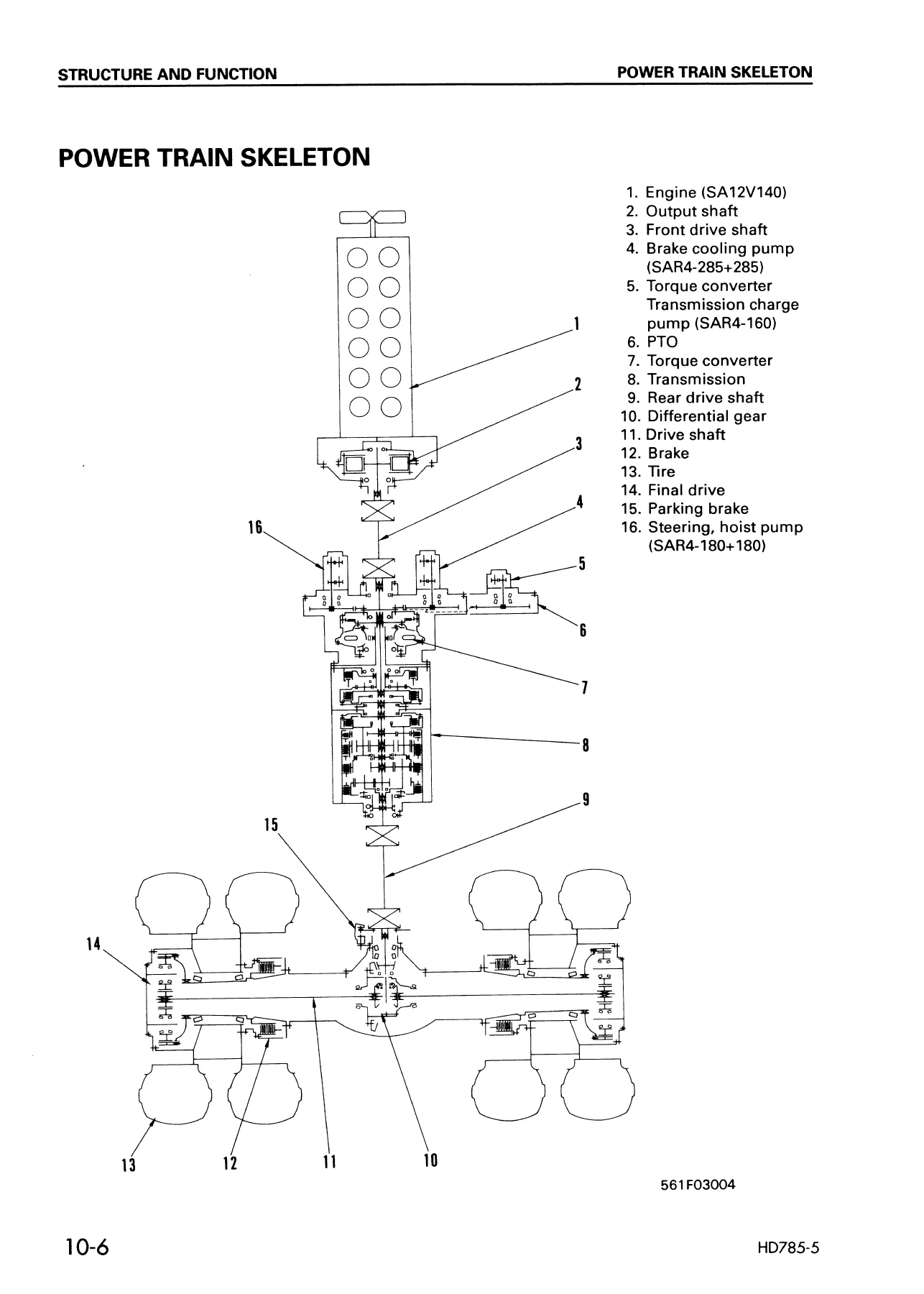
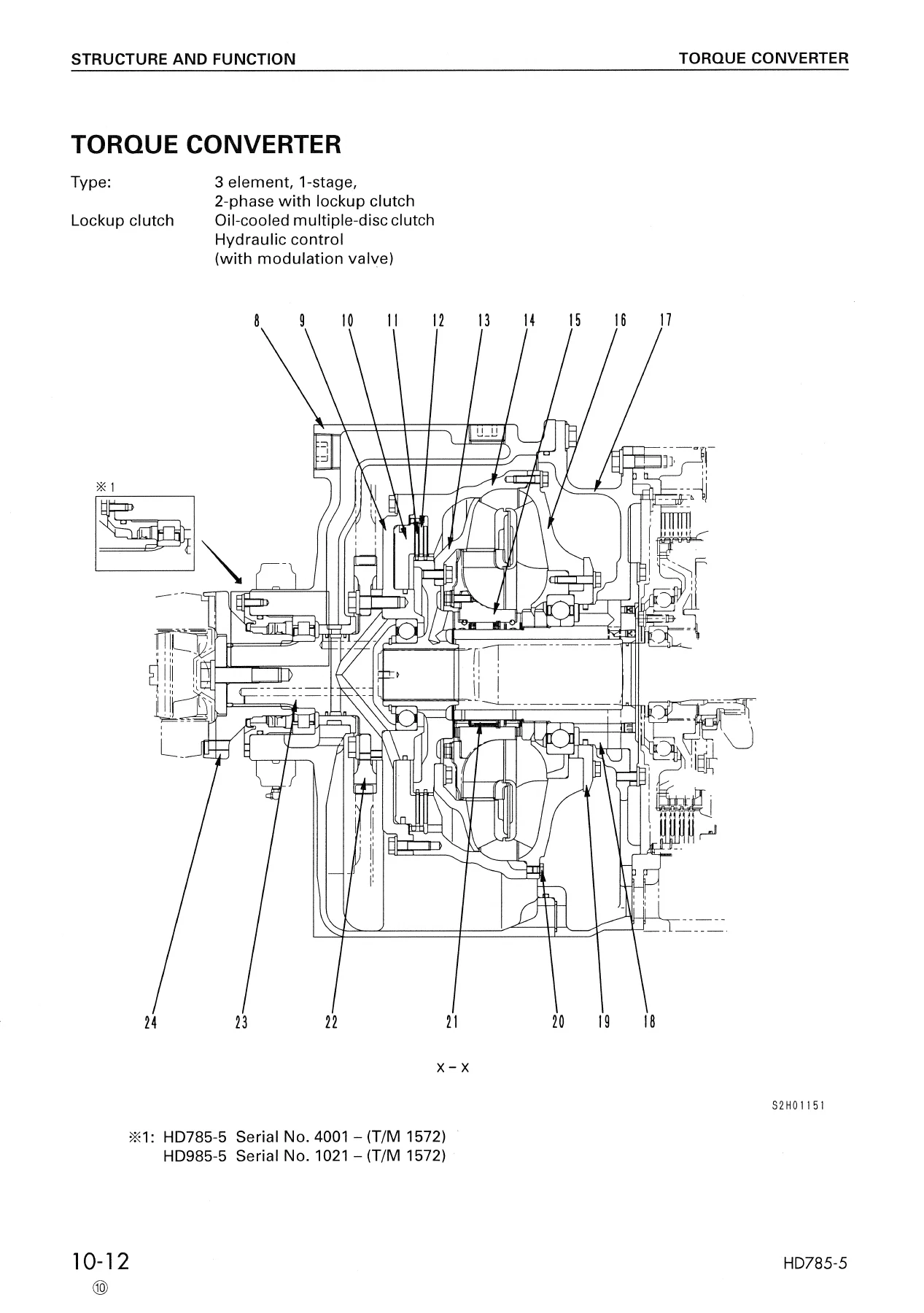
- 10 STRUCTURE AND FUNCTION — radiator and torque converter cooler, brake oil cooler, power train skeleton, output shaft, torque converter and transmission hydraulic circuit, torque converter valve, lockup solenoid valve, transmission, transmission valve, ECMV, lubrication relief valve, front and rear axles, differential, differential lock control, final drive, front brake, rear brake, parking brake, wheels, axle support, steering system and linkage, suspension system and cylinders, air piping and air circuit, brake valve, emergency brake control valve, parking brake control valve, relay valve, quick-release valve, brake chambers, slack adjuster, hydraulic piping and circuit diagram, dump body control, hydraulic tank, brake cooling oil control valve, steering valve, demand valve, hoist valve, crossover relief valve, steering cylinder, hoist cylinder, electrical circuit diagrams, stop lamp switch, exhaust brake, tilt switch, front brake cut-off valve, horn valve, air conditioner, engine control system, fuel injection pump electronic governor, AISS, exhaust brake system, automatic shift control system, transmission controller, shift lever switch, sensors and switches, self-diagnostic function, automatic emergency steering system, flow switch, relay timer, automatic suspension system, suspension controller, payload meter (printer type and card type), machine monitor system, PMC system, maintenance monitor system, ABS/ASR system, ASR-II system, hydraulic tank pressurizing system (high altitude specification)
- 20 TESTING AND ADJUSTING — tools for testing, adjusting and troubleshooting, valve clearance, compression pressure, blowby pressure, boost pressure, exhaust temperature, fuel injection timing, alternator belt tension, engine and transmission speed sensors, accelerator pedal, torque converter valve hydraulic pressure, ECMV hydraulic pressure, transmission lubrication pressure, torque converter stall speed, brake pressure, bleeding air from brake circuit, front brake pad and rear brake disc wear, parking brake adjustment, brake performance, front and rear suspension cylinder testing (including variable damping force selector valve), suspension air cylinder, air circuit pressure, hoist lever linkage, body positioner, steering and hoist hydraulic pressure, air bleeding from steering cylinder, electronic monitor adjustment, fuel injection amount when replacing engine controller, rotary switch settings for transmission controller replacement, memory deletion from engine/transmission/PMC controllers, emergency escape procedure for electrical failures, modulation checker operation, hydraulic tank pressure adjustment (high altitude spec), Pm clinic using manual snapshot, Pm-clinic service
- 30 DISASSEMBLY AND ASSEMBLY — starting motor, alternator, engine oil cooler, left and right bank fuel injection pumps, air compressor, water pump, aftercooler core, turbocharger, nozzle holder, cylinder head, exhaust brake, engine, engine front and rear seals, radiator and torque converter cooler, brake cooler, output shaft, torque converter and transmission, torque converter control valve, torque converter PTO, transmission, ECMV, differential (standard and with differential lock), front wheel, front brake caliper and pad, front wheel hub, final drive carrier, final drive, rear brake, rear wheel brake, parking brake pad and caliper, front and rear suspension cylinders, variable damping selector valve, air governor, brake valve, parking brake chamber, rear brake chamber, front brake chamber, slack adjuster, brake cooling pump, steering and hoist pump, torque converter and transmission pump, emergency steering motor pump, steering valve, brake control valve (BCV), demand valve, relief valve, hoist valve, steering cylinder, hoist cylinder, body, controller, air conditioner compressor, receiver tank, air conditioner condenser
- 40 MAINTENANCE STANDARD — output shaft, torque converter valve, torque converter, transmission, ECMV, front axle, front axle with ABS/ASR, rear axle support, differential, final drive, front brake, rear brake, rear brake with ABS/ASR, parking brake, steering linkage, front suspension cylinder, rear suspension cylinder, parking brake chamber, slack adjuster, hydraulic pumps, demand valve, crossover relief valve, hoist valve, steering cylinder, hoist cylinder
- 90 OTHERS — hydraulic circuit diagrams, electric circuit diagrams, and specifications of attachments and options
This is a working document, not a marketing brochure. Each chapter is built for a specific job on the shop floor: STRUCTURE AND FUNCTION shows how a system is put together and why it behaves the way it does, TESTING AND ADJUSTING gives the pressures, speeds and clearances to check before and after a repair, DISASSEMBLY AND ASSEMBLY walks through removal, disassembly, assembly and installation of each major component with the special tools and tightening torques called out, and MAINTENANCE STANDARD provides the wear limits, backlash values, thickness tolerances and repair limits used to decide whether a part is serviceable or scrap. Read together, the four chapters let a technician diagnose a fault, verify it with a gauge or a test, repair it correctly, and then confirm the repair before the truck goes back into service.
Machines This Manual Covers
The HD785-5 and HD985-5 are Komatsu rigid-frame off-highway dump trucks used in mining, quarrying and large-scale earthmoving. The manual is written to the serial-number break for each: HD785-5 from 4001 and up, HD985-5 from 1021 and up. Both are powered by the Komatsu SA12V140-1 four-cycle, water-cooled, V-type 12-cylinder direct-injection diesel with turbocharger and aftercooler. Where a machine spec differs between the two models — standard tire size, body capacity, rated load, axle housing, final drive, brake cooling, suspension, steering — the manual separates the two so you apply the right procedure to the right truck.
Systems a Technician Can Service From This Manual
The coverage runs from the front axle through the power train to the rear axle and back into every support system on the truck. On the power train side that means the output shaft, torque converter with lockup clutch, TORQFLOW planetary transmission with its seven forward and one reverse range, the electronically controlled modulation valves (ECMV) that regulate each clutch, the differential (standard and differential-lock), final drive, and the drive shafts. On the chassis side it covers front and rear axle, wheel hubs, front brake caliper and pads, rear oil-cooled multiple-disc brake, parking brake caliper and chamber, slack adjuster, and the brake cooling circuit. Steering, hoist and suspension are covered with their cylinders, valves and linkage, as are the air system components (air governor, safety valve, check valve, double check valve, auto drain valve, hand brake valve, brake valve, emergency and parking brake control, relay valves, quick-release valve, ratio valve, brake chambers). The electrical side gives you the cab wiring diagrams, engine control system, automatic shift control system, transmission controller, self-diagnostic functions, automatic emergency steering, automatic suspension, payload meter, machine monitor, PMC, maintenance monitor, ABS/ASR and ASR-II. The air conditioning system is also included.
What the Testing and Adjusting Chapter Gives You
Fault-finding on a machine of this size depends on numbers, not guesswork. The TESTING AND ADJUSTING chapter supplies them: how to check and set valve clearance, how to measure compression, blowby and boost pressure, how to check exhaust temperature and fuel injection timing, how to set alternator belt tension and adjust the engine and transmission speed sensors and the accelerator pedal, how to test the torque converter valve, ECMV, transmission lubrication and torque converter stall speed, how to check brake pressure and bleed the brake circuit, how to measure front brake pad and rear brake disc wear, how to adjust the parking brake and confirm brake performance, how to test and adjust the front and rear suspension cylinders and the suspension air cylinder, how to check air circuit pressure, how to adjust the hoist lever linkage and body positioner, how to test steering and hoist hydraulic pressure, how to bleed the steering cylinder, and how to adjust the electronic monitor. It also covers the procedures that only come up occasionally: replacing the engine controller and resetting fuel injection amount, setting the rotary switches when replacing the transmission controller, deleting stored data from the engine, transmission and PMC controllers through the monitor panel, the emergency escape procedure when the electrical system fails, using the modulation checker, adjusting hydraulic tank pressure on high-altitude specification machines, and running a Pm clinic through the manual snapshot function.
Who This Manual Is For
This is a professional shop manual. It is written for the mechanic, the fleet maintenance planner and the technically minded owner who needs factory procedures, factory pressures and factory wear limits rather than a generic repair guide. The procedures assume access to a workshop with lifting equipment, torque wrenches, hydraulic test gauges and the special tools listed in the special tool list. Where a component must be lifted, the manual states the weight; where a fastener needs a specific torque, the torque is given in Nm and kgm; where a tolerance decides whether a part is reusable, the tolerance is printed in the maintenance standard tables.
How to Use It
Start with the section that matches what you are doing. If a system is behaving oddly, read its STRUCTURE AND FUNCTION entry first so you understand how it works. Then use TESTING AND ADJUSTING to confirm the fault with measurements. Use DISASSEMBLY AND ASSEMBLY to remove and rebuild the component, and MAINTENANCE STANDARD to judge which parts to replace. The chapter contents pages at the start of each section list every sub-heading, so you can jump straight to the page you need. The revised-page list at the front identifies which pages have been updated in this edition, so you are never working from a superseded procedure.
Buy the Komatsu HD785-5 HD985-5 Shop Manual Today
With this Komatsu HD785-5 HD985-5 shop manual on hand you can diagnose faults, adjust systems to specification, rebuild major components, and confirm your work against the maintenance standard values — all without chasing partial documents or guessing at torques and clearances. It covers the HD785-5 and HD985-5 from the serial numbers listed above, includes the full testing and adjusting chapter, and gives you the complete disassembly and assembly sequences with the special tool numbers and tightening torques called out. Delivery is instant: the moment your order is confirmed you get the PDF, no shipping, no waiting on a courier. Read it on a laptop, tablet or phone in the workshop, or print the pages you need for the job in front of you. Whether you are servicing the transmission, chasing an ECMV fault, rebuilding a rear brake, adjusting the suspension or setting up the automatic shift control system, the answers are in the pages you get today.
IMAGES PREVIEW
Reviews
There are no reviews yet.