
Komatsu HM400-3M0 Articulated Dump Truck Shop Manual – Serial 5001-Up Complete PDF Repair Guide
Original price was: $52.95.$34.95Current price is: $34.95.
The complete Komatsu HM400-3M0 Articulated Dump Truck Shop Manual (SEN06284-06) for serial numbers 5001 and up. Over 1,980 pages covering engine, power train, hydraulics, brakes, steering, electrical systems, troubleshooting, disassembly, assembly and full specifications. Instant PDF download.
Description
Komatsu HM400-3M0 Articulated Dump Truck Shop Manual – Complete Service & Repair Documentation
This is the complete Komatsu HM400-3M0 Articulated Dump Truck Shop Manual, the comprehensive technical resource covering every major system, component, and service procedure for machines with serial numbers 5001 and up. Identified by document number SEN06284-06 and published under Komatsu copyright in 2016, this shop manual spans the full service spectrum — from engine and cooling through power train, hydraulics, brakes, steering, electrical systems, troubleshooting, disassembly and assembly, maintenance standards, and complete circuit diagrams. Whether you are a fleet mechanic, an independent technician, or an owner-operator performing your own repairs, this manual delivers the depth of information required to service the HM400-3M0 correctly and safely.
File Details
- Manual type: Shop Manual (Service, Repair & Troubleshooting)
- Brand / Model: Komatsu HM400-3M0
- Serial number coverage: 5001 and up
- Document number: SEN06284-06
- Edition / revision: Rev. 2014/08 and later revisions incorporated
- Publication date: 2016
- Language: English
- File format: PDF
- Page count: 1,986
Chapters Covered
- 01 Specification
- 10 Structure and Function
- 20 Standard Value Tables
- 30 Testing and Adjusting
- 40 Troubleshooting
- 50 Disassembly and Assembly
- 60 Maintenance Standard
- 80 Appendix (Air Conditioner)
- 90 Diagrams and Drawings
01 Specification
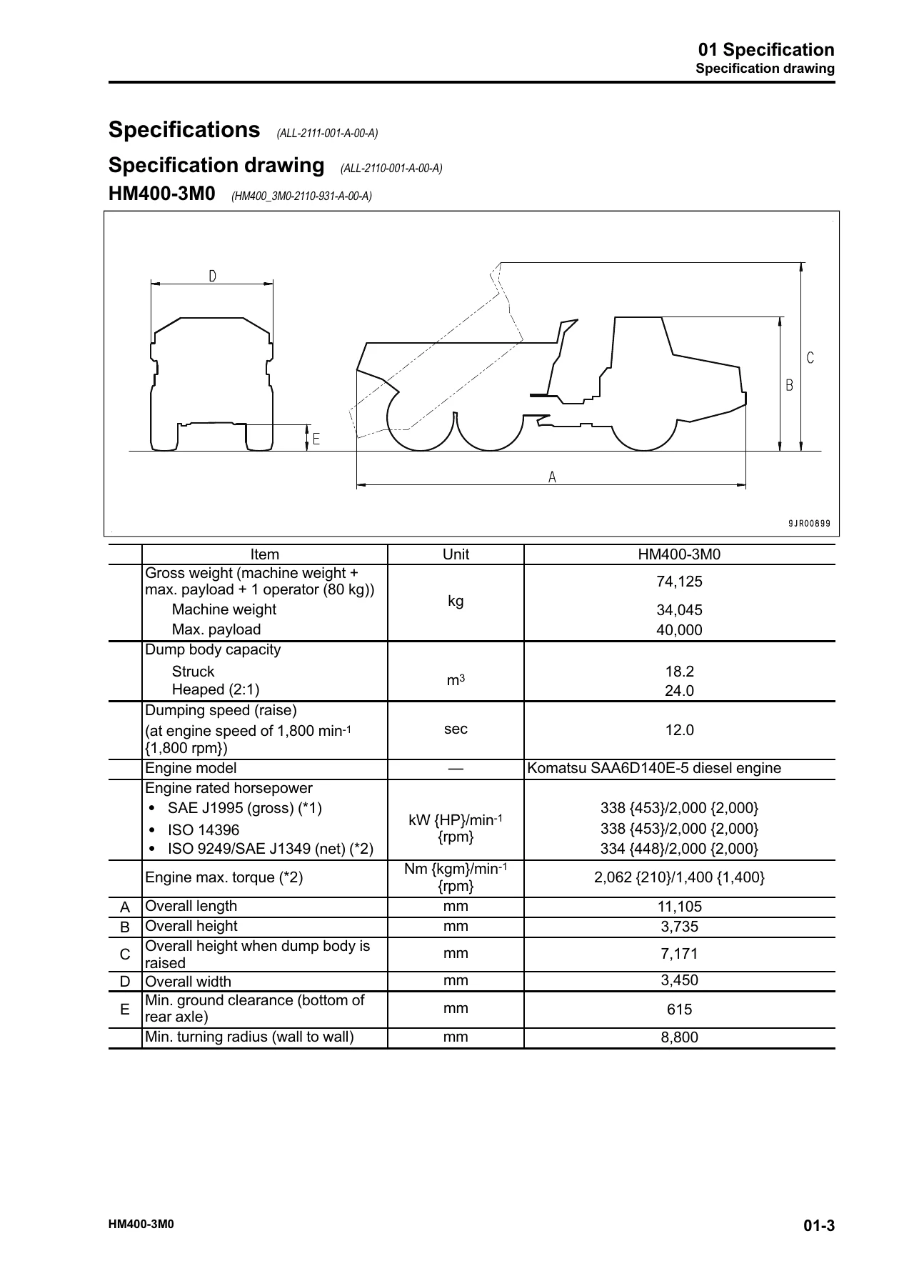
This chapter opens with the specification drawing and full machine specifications for the HM400-3M0, covering dimensions, engine rated horsepower, torque, weight distribution, dump body capacity, travel speeds, gradeability, tire sizes, brake types, and hydraulic system pump and motor data. A dedicated weight table provides component weights for handling and transport, and a comprehensive fuel, coolant, and lubricant table lists capacities and recommended fluids for every reservoir on the machine.
10 Structure and Function
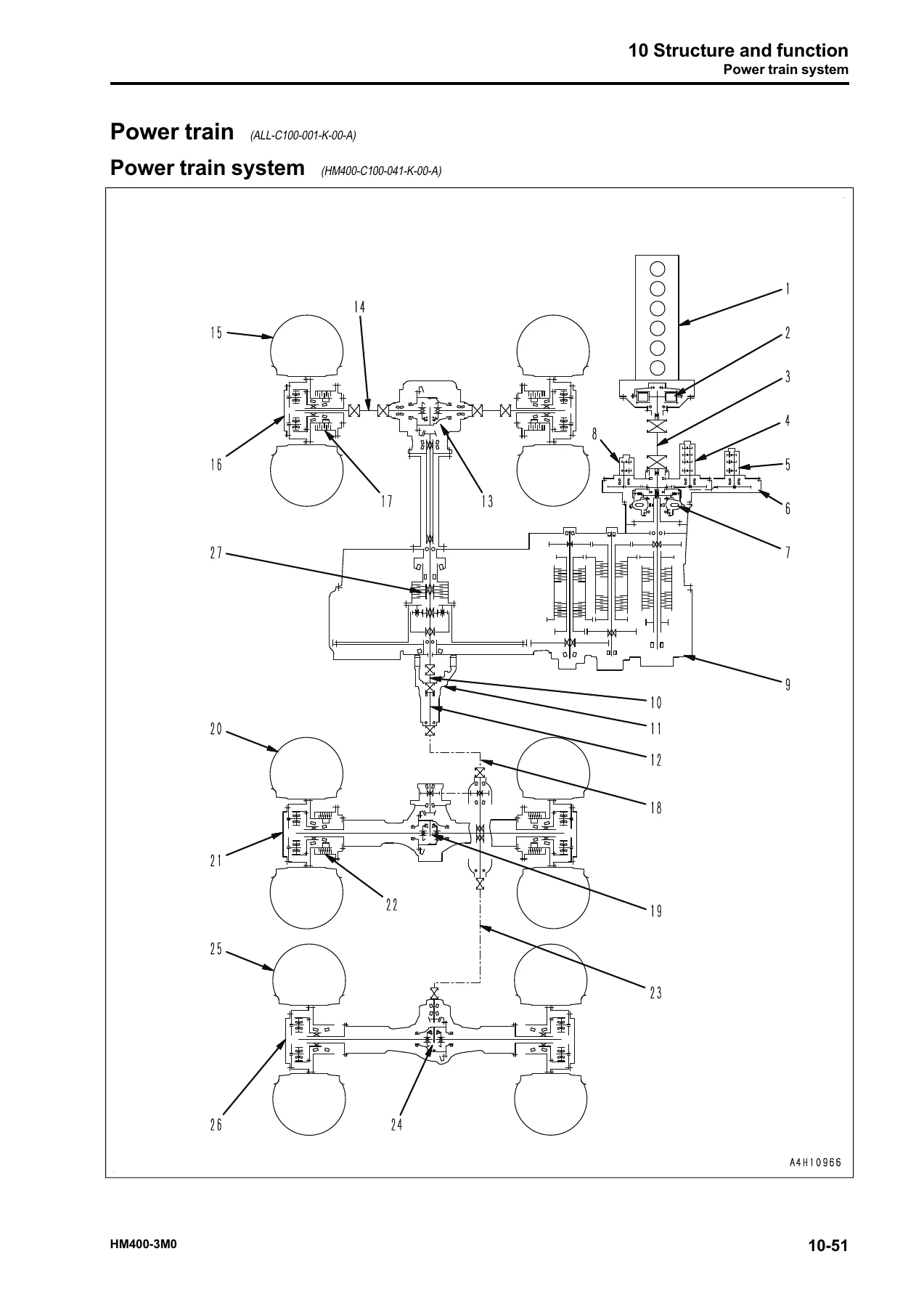
The largest reference section in the manual, this chapter explains how each major system on the HM400-3M0 is constructed and how it operates. It begins with the engine and cooling system — output shaft, turbocharger, EGR system layout and circuit, EGR valve, bypass valve, Venturi system, EGR cooler, muffler, radiator fan pump, aftercooler fan motor, radiator fan motor, and oil cooler bypass valve. The power train section covers the torque converter, transmission, transmission control valve, forward and reverse clutch ECMV, gear speed clutch ECMV, lockup clutch ECMV, differential lock clutch ECMV, main relief valve, torque converter relief valve, main flow selector valve, axle, differential, and final drive. Steering system coverage includes the steering column, flow amplifier valve, steering valve, emergency steering pump, and emergency steering motor. Brake system layout, parking brake solenoid and accumulator charge valve, accumulator, shut off solenoid valve, brake valve, proportional pressure reducing valve, slack adjuster, brake, brake system tank, and parking brake are all documented. Undercarriage and frame coverage includes suspension, suspension cylinder, and oscillation hitch. The hydraulic system section details the hydraulic component layout, dump body control, hydraulic tank, steering and hoist pump, hoist valve, steering pump selector solenoid valve, dump EPC valve, center brake cooling remote motor, front brake cooling relief valve, and center brake cooling relief valve. Cab and electrical sections cover the ROPS cab, cab tilt, electrical control system, machine monitor system, rear view monitor system, KOMTRAX system, system component parts, and sensors.
20 Standard Value Tables
This chapter provides the standard service value tables for both engine and machine. The engine standard value table covers speeds, boost pressure, exhaust temperature, exhaust gas colour, valve clearance, compression pressure, blowby pressure, oil pressure, EGR valve and bypass valve driving oil pressure, oil temperature, fuel pressure, and fuel return rate. The machine standard value table covers engine speeds at torque converter lockup, transmission upshift and downshift, travel speeds, tire inflation pressure, brake pedal effort and travel, retarder lever operation, accumulator gas pressure, charge valve cut-in and cut-out pressures, wheel brake operating pressure, braking performance, steering wheel operating effort and play, suspension cylinder installed lengths and pressures, dump lever effort, dump body raise and lower times, hydraulic drift, main relief pressure, pilot relief pressure, and radiator and aftercooler fan speeds.
30 Testing and Adjusting
This section describes the tools required for testing and adjusting, with sketches and part numbers, and then walks through every test and adjustment procedure for the HM400-3M0. Engine and cooling system procedures include testing engine speed, boost pressure, exhaust gas temperature, exhaust gas colour, adjusting valve clearance, testing compression pressure, blowby pressure, engine oil pressure, EGR valve and bypass valve drive pressure, fuel pressure, fuel return rate and leakage, bleeding air from the fuel system, testing the fuel circuit for leakage, testing radiator and aftercooler fan speeds, and adjusting alternator and air conditioner compressor belt tension. Power train procedures cover testing torque converter stall speed, testing power train oil pressure, adjusting transmission speed sensors, adjusting the transmission controller, and retrieving a disabled machine. Steering, brake, hydraulic, work equipment, cab, and electrical system procedures are included, with a large special functions section for the machine monitor.
40 Troubleshooting
The troubleshooting chapter is one of the most detailed in the manual. It begins with troubleshooting points, sequence of events, checks before troubleshooting, inspection procedure, preparation for electrical system troubleshooting, classification and procedures, symptom and troubleshooting numbers, information in troubleshooting tables, and a connector list and layout with contact identification, T-branch box and adapter tables, fuse location table, and precautions for machine monitor troubleshooting. The failure codes table lists every diagnostic code the machine can display, followed by troubleshooting by failure code for each code. An E-mode section covers electrical system troubleshooting with symptom-based procedures. An H-mode section covers hydraulic and mechanical system troubleshooting with a system chart, failure mode and cause table, and symptom-based procedures. An S-mode section covers engine troubleshooting with symptom-based procedures for starting, running, and performance issues.
50 Disassembly and Assembly
This chapter provides the removal, installation, disassembly, and assembly procedures for every major component and assembly on the HM400-3M0. It opens with related information on how to read the manual, a coating materials list, special tools list, and sketches of special tools. Engine and cooling system procedures cover the supply pump, injector, cylinder head, radiator, radiator core, radiator cooling fan and fan motor, aftercooler, aftercooler cooling fan and fan motor, engine assembly, engine front and rear oil seals, output shaft assembly, air cleaner assembly, EGR valve assembly, EGR cooler assembly, and exhaust pipe fire prevention cover. Power train procedures cover the transmission and front differential assembly, front differential disassembly and assembly, torque converter, transmission, center differential, rear differential, front final drive and brake, center final drive and brake, rear final drive, center axle, and rear axle. Steering system, undercarriage and frame, hydraulic system, body, cab and attachments, electrical system, and air conditioner unit procedures are all documented.
60 Maintenance Standard
This chapter provides the maintenance standard values, wear limits, clearances, and tolerances for every major component. It covers the engine mount, output shaft, radiator fan pump, radiator fan motor, aftercooler fan motor, drive shaft, torque converter and transmission mount, torque converter, transmission, transmission control valve, forward and reverse clutch ECMV and gear speed clutch ECMV, lockup clutch ECMV, differential lock clutch ECMV, main relief valve, torque converter relief valve, main flow selector valve, differential, axle, final drive, steering column, steering cylinder, emergency steering pump, slack adjuster, brake, parking brake, suspension, suspension cylinder, oscillation hitch, steering and hoist pump, pump for driving torque converter, transmission, aftercooler fan and center brake cooling motors, center brake cooling pump, brake charge pump, center brake cooling remote pump, center brake cooling remote motor, hoist valve, and hoist cylinder.
80 Appendix — Air Conditioner
The appendix covers the air conditioner system in full, including precautions for refrigerant, air conditioner components, configuration and function of the refrigeration cycle, air conditioner unit, dual pressure switch, air conditioner controller, compressor, condenser, receiver drier, and outer temperature sensor. Testing and troubleshooting procedures include air leakage testing, self-diagnosis function, vent changeover testing, FRESH/RECIRC air changeover testing, pressure switch testing, relay testing, troubleshooting charts, failure code list related to air conditioner, power supply system troubleshooting, compressor and refrigerant system troubleshooting, blower motor system troubleshooting, and troubleshooting with gauge pressure. Connection of service tool, precautions for disconnecting and connecting air conditioner piping, and handling of compressor oil are also included.
90 Diagrams and Drawings
This chapter provides the complete hydraulic circuit diagram with symbols, power train hydraulic circuit diagram, full hydraulic circuit diagrams, and electrical circuit diagrams with symbols. It includes inside cab electrical circuit diagrams, outside cab electrical circuit diagrams, and the electrical circuit diagram of the engine. These diagrams are essential for understanding system operation and tracing faults in the hydraulic and electrical systems.
Why This Komatsu HM400-3M0 Shop Manual Is Essential
The HM400-3M0 Articulated Dump Truck is a complex piece of heavy equipment with interconnected hydraulic, electrical, and mechanical systems. Without the correct procedures, specifications, and diagnostic information, even routine maintenance can lead to costly mistakes. This shop manual gives you the same technical depth that Komatsu-trained technicians use, covering every system from the engine and torque converter through to the hoist valve and air conditioner.
With this manual, you can confidently perform engine diagnostics and rebuilds, transmission and torque converter repairs, hydraulic system testing and adjustment, brake system service, suspension work, electrical troubleshooting using the failure code tables and circuit diagrams, and complete component disassembly and assembly. The standard value tables and maintenance standards give you the exact wear limits, clearances, and adjustment values so you know when a part is within specification and when it must be replaced. The troubleshooting chapter helps you diagnose faults efficiently using the machine’s own failure codes and symptom-based procedures, saving hours of guesswork.
IMAGES PREVIEW
Delivered as an instant PDF download, this Komatsu HM400-3M0 shop manual can be accessed on any device — laptop, tablet, or smartphone — and printed for use in the workshop. There is no shipping wait and no physical media to lose. Whether you are maintaining a fleet, performing a single repair, or simply want the correct reference on hand, this PDF manual provides the complete technical documentation for the HM400-3M0 in one convenient file.

Reviews
There are no reviews yet.