
Komatsu PC138USLC-11 Shop Manual SEN06589-03 – Complete PDF Service & Repair Guide
Original price was: $59.95.$39.95Current price is: $39.95.
Complete Komatsu PC138USLC-11 Shop Manual (SEN06589-03) covering specifications, structure and function, testing and adjusting, troubleshooting, disassembly and assembly, maintenance standards and full circuit diagrams for the SAA4D95LE-7 engine and hydraulic excavator.
Description
Komatsu PC138USLC-11 Shop Manual — SEN06589-03
This is the complete Komatsu PC138USLC-11 Shop Manual, document number SEN06589-03. It is the full workshop reference published by Komatsu for the PC138USLC-11 hydraulic excavator, and it is the same manual a Komatsu service technician works from in the shop. Everything is covered in one document: engine service data, hydraulic system theory and repair, electrical diagnostics, undercarriage, work equipment, cab, air conditioning, and the complete hydraulic and electrical circuit diagrams. Use the search box above to verify your exact machine — the manual covers the PC138USLC-11 fitted with the Komatsu SAA4D95LE-7 diesel engine.
File Details
- Manual type: Shop Manual (Service, Repair, Testing & Troubleshooting)
- Brand: Komatsu
- Model: PC138USLC-11
- Engine: SAA4D95LE-7
- Document number: SEN06589-03
- Language: English
- Page count: Approximately 2,425 pages
- File format: PDF
Chapters Covered
- 00 INDEX AND FOREWORD
- 01 SPECIFICATIONS
- 10 STRUCTURE AND FUNCTION
- 20 STANDARD VALUE TABLE
- 30 TESTING AND ADJUSTING
- 40 TROUBLESHOOTING
- 50 DISASSEMBLY AND ASSEMBLY
- 60 MAINTENANCE STANDARD
- 80 APPENDIX
- 90 CIRCUIT DIAGRAMS
00 Index and Foreword
Opens with the full abbreviation list used across the manual, followed by the foreword, safety notices, fire prevention and fire response procedures, waste disposal precautions, exhaust gas regulation actions, DEF handling and storage, and the practical precautions for handling hydraulic, electrical, fuel and intake system equipment. Also included are the push-pull coupler and connector disconnection/connection methods, the electrical wire code reader, the tightening torque tables and the unit conversion tables. Every safety symbol and signal word used later in the manual is defined here.
01 Specifications
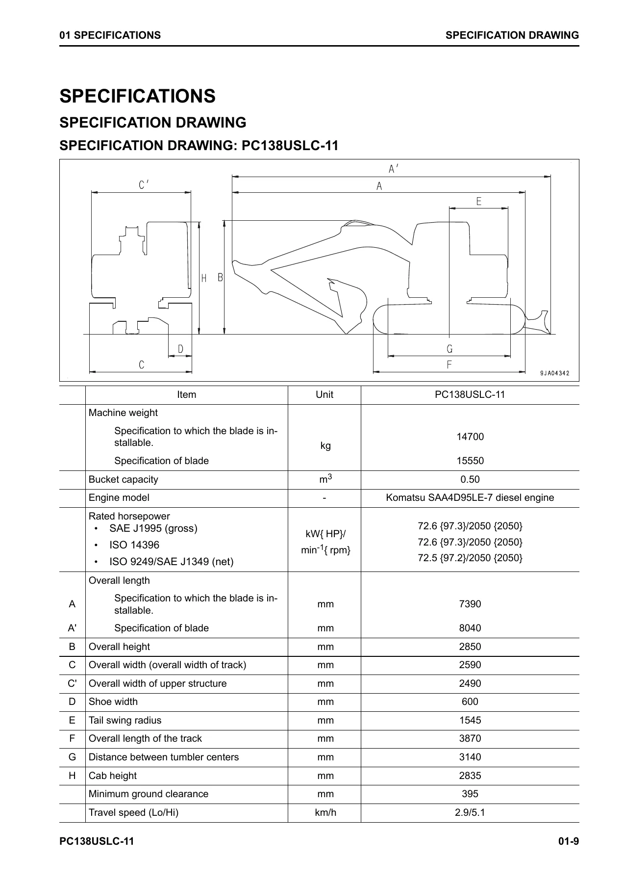
Contains the PC138USLC-11 specification drawings, working range drawings and the full specification tables — bucket capacity, machine weight, engine rated horsepower, travel speed, gradeability, ground pressure, overall dimensions, cab height, tail swing radius and track dimensions. There is a separate weight table for major components and assemblies (engine, main pump, cab, counterweight, boom, arm, bucket, cylinders, track frame, travel motor, swing machinery) and the complete table of fuel, coolant and lubricants with capacities and ambient temperature ranges.
10 Structure and Function
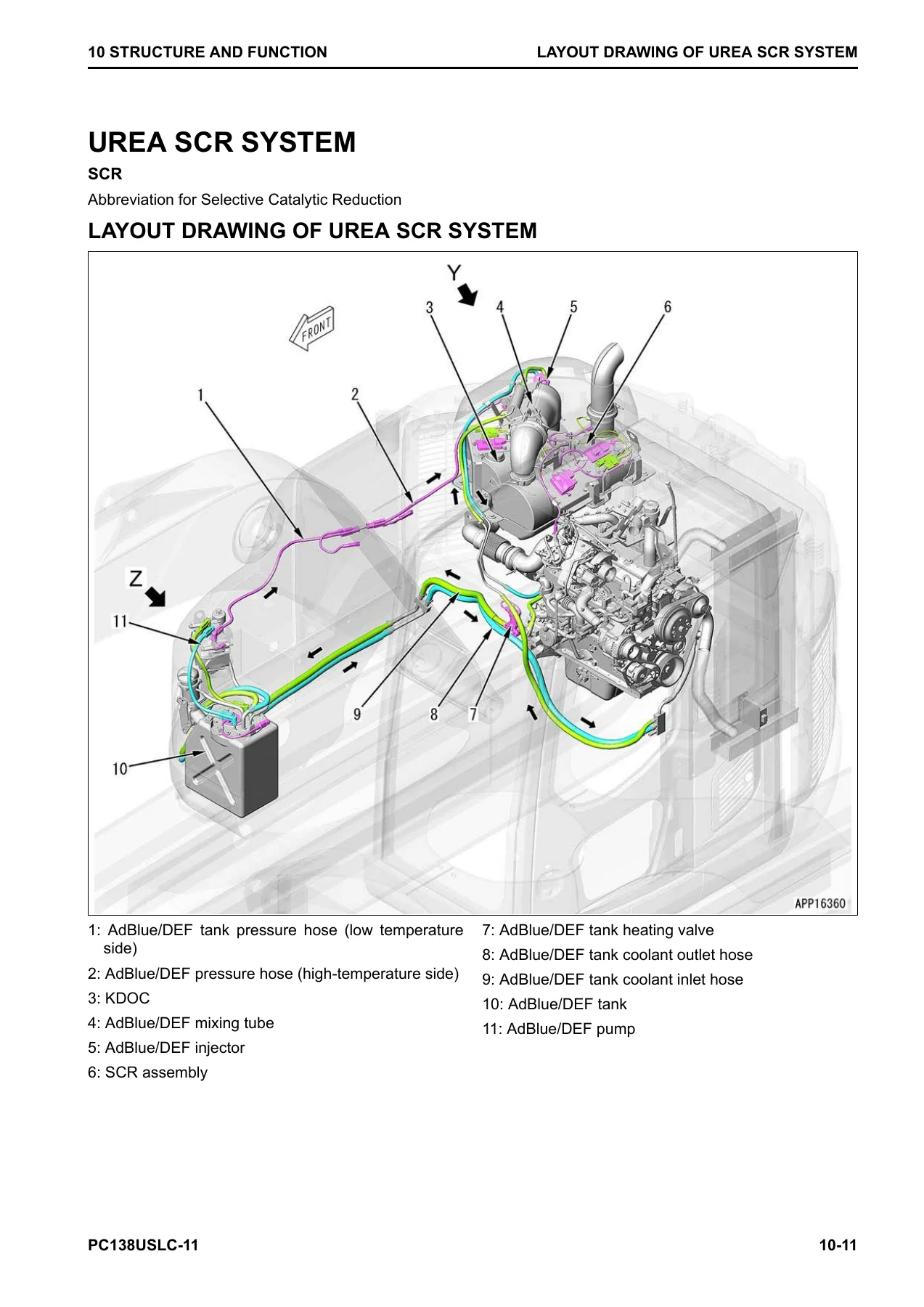
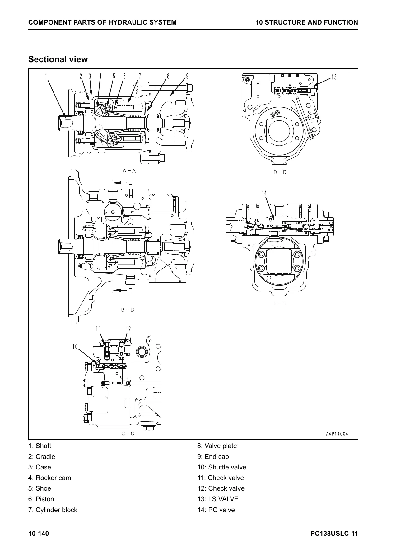
The largest technical chapter. It begins with the urea SCR system — layout drawing, system diagram, function description, component parts, inducement strategy tables for North America and the European Union, and the temporary restoration from inducement procedure. Then the boot-up system, system operating lamp, battery disconnect switch, engine control system, auto-deceleration, automatic warm-up, overheat prevention, turbocharger protection, automatic idle stop, PTO, variable flow turbocharger, EGR system, KCCV system, exhaust throttle valve and KDOC. Following that is the full cooling system, control system (machine monitor, KomVision, KOMTRAX), hydraulic system (CLSS, engine and pump combined control, hydraulic tank, main pump with LS and PC valves, PC-EPC valve, check valve, shuttle valve, control valve with every spool and valve), work equipment system (PPC lock, automatic lock, attachment oil flow adjuster, PPC valves, solenoid valves), swing system (swing motor, swing machinery, swing circle), travel system (travel motor, travel PPC valve, center swivel joint), undercarriage and frame, work equipment and cab attachments.
20 Standard Value Table
Two standard value tables — one for the engine and one for the machine. The engine table lists engine speed at high and low idle, exhaust gas colour, valve clearance, compression pressure, blowby pressure, fuel pressure, fuel return rate, leakage from pressure limiter, engine oil pressure, engine oil temperature, fan belt tension, air conditioner compressor belt tension and cooling fan speed. The machine table lists engine speed at pump relief, speed around rated speed, auto-deceleration speed, AdBlue/DEF pump pressure up test, injector resistance, injection quantity, line heater relay voltages, SCR denitration efficiency, control lever travel and play, operating effort, work equipment / swing / travel / blade oil pressures, PC valve outlet pressure, PC-EPC valve outlet pressure, LS valve outlet pressure, LS differential pressure, solenoid valve outlet pressure, variable back pressure solenoid valve outlet pressure, PPC valve outlet pressure, swing overrun, swing start time, swing finish time, swing drift on slope, swing motor leakage, travel speed, travel deviation, machine drift on slope, travel motor leakage, hydraulic drift of work equipment, work equipment speeds, time lags, oil leakage, and pump performance curves. Includes the machine posture and measurement procedure figures.
30 Testing and Adjusting
Every measurement, test and adjustment is documented with tools, measuring locations, conditions and criteria. Engine and cooling system topics include engine speed, exhaust gas colour, exhaust throttle valve clearance, valve clearance, compression pressure, blowby pressure, engine oil pressure, fuel pressure, fuel return rate and leakage, air bleeding from the fuel system, fuel circuit leakage, cylinder cut-out mode, no-injection cranking, air conditioner compressor belt tension, alternator belt, automatic tensioner, cooling fan speed, writing injector compensation values to the engine controller, and every SCR-related function test (AdBlue/DEF pump raised pressure, injection amount from injector, line heater relay 1 and 2, pump heater relay, tank heater valve, denitration efficiency of SCR, cleaning AdBlue/DEF tank, bleeding air from coolant circuit of AdBlue/DEF tank). Power train covers swing circle bearing clearance. Undercarriage covers track tension. Hydraulic system covers releasing remaining pressure, testing and adjusting oil pressure in work equipment / swing / travel / blade circuits, control circuit oil pressure, pump PC control circuit, pump LS control circuit, solenoid valve outlet pressure, PPC valve outlet pressure, travel deviation, parts causing hydraulic drift, oil leakage and bleeding air from the hydraulic circuit. Cab and electrical sections cover cab tipping stopper, mirror adjustment, machine monitor service and operator modes, KOMTRAX start-up, rearview and KomVision camera adjustment, engine controller voltage circuit, battery disconnect switch, diodes, and the Pm Clinic service check sheet for the PC138USLC-11.
40 Troubleshooting
The largest troubleshooting collection in this manual. General troubleshooting points for the urea SCR system include loaded diagnostics, clearing failure codes, Inducement strategy, and the failure code lists for Inducement that cannot be cleared while output power is derated. Then the failure codes table covers every code from 879AKA through CA5938 and beyond, with a dedicated page for each code showing details of failure, action of controller, phenomenon on machine, related information, and step-by-step troubleshooting procedure with measuring locations and criteria. Following the code-based section are the E-mode electrical troubleshooting procedures (E-1 through E-54), the H-mode hydraulic and mechanical troubleshooting procedures (H-1 through H-38), and the S-mode engine troubleshooting procedures (S-1 through S-26). Each mode includes a symptoms-of-failure index, information on how to read the troubleshooting tables, and the full procedure for that symptom.
50 Disassembly and Assembly
Removal, installation, disassembly and assembly procedures for every major component. Engine and cooling system: supply pump assembly, injector assembly, cylinder head assembly, EGR valve assembly, EGR cooler assembly, starter assembly, alternator belt, automatic tensioner, radiator assembly, hydraulic oil cooler assembly, aftercooler assembly, fan clutch assembly, engine and main pump assembly, engine front and rear oil seals, fuel cooler assembly, KDOC assembly, KDOC and SCR assembly, fuel tank assembly, AdBlue/DEF tank assembly, AdBlue/DEF tank sensor flange assembly, AdBlue/DEF tank sensor, AdBlue/DEF tank strainer, SCR assembly, KDOC and SCR assembly bracket, bellows pipe assembly, KCCV assembly, exhaust throttle valve, AdBlue/DEF mixing tube, AdBlue/DEF injector, AdBlue/DEF pump, AdBlue/DEF hose, air cleaner assembly, air conditioner compressor assembly and air conditioner condenser assembly. Power train: travel motor and final drive assembly (including full disassembly and assembly), swing motor and swing machinery assembly (including full disassembly and assembly of swing machinery), swing circle assembly. Undercarriage and frame: track assembly separation and connection, sprocket, idler and idler cushion assembly, idler assembly, idler cushion assembly, track roller assembly, revolving frame assembly, counterweight assembly. Hydraulic system: center swivel joint assembly (including disassembly and assembly), hydraulic tank assembly, main pump assembly, control valve assembly (including disassembly and assembly and the pressure reducing valve cartridge replacement method), work equipment PPC valve assembly, travel PPC valve assembly. Work equipment: blade assembly, work equipment assembly, work equipment cylinder assembly. Cab: operator’s cab assembly, cab door, cab glass (adhered glass), front window assembly, floor frame assembly, air conditioner unit assembly, operator’s seat, seat belt, front wiper assembly. Electrical: engine controller assembly, pump controller assembly, KomVision controller assembly, machine monitor assembly, mass air flow and temperature sensor, KCCV crankcase pressure sensor, SCR temperature sensor, rearview camera, KomVision camera, KOMTRAX terminal assembly. Every procedure lists the special tools required by symbol, the tightening torques, the coating materials, the weights, and the required safety precautions.
60 Maintenance Standard
The judgment criteria tables for deciding whether a disassembled part can be reused or must be replaced. Covers engine mount, PTO, cooling system, swing circle, swing machinery, sprocket, track frame and idler cushion, idler, track roller, carrier roller, track shoe, triple shoe, road liner, hydraulic tank, main pump, PC-EPC valve, swing motor, travel motor, control valve, work equipment and swing PPC valve, blade PPC valve, travel PPC valve, 1st-line attachment PPC valve with EPC valve, EPC valve of 1st-line attachment PPC valve, solenoid valve, variable back pressure solenoid valve, attachment circuit selector valve for high pressure, attachment circuit selector valve for low pressure, attachment circuit accumulator, center swivel joint, work equipment linkage (including dimensions of arm and bucket), boom cylinder, arm cylinder, bucket cylinder, blade cylinder and cab mount. Standard dimensions, tolerances, standard clearances, allowable clearances, standard interference and allowable interference are given for each part, together with the remedy.
80 Appendix — Air Conditioner System
The complete air conditioner section. Precautions for refrigerant, air conditioner component identification, specifications, configuration and function of the refrigeration cycle, air conditioner unit (evaporator, heater core, evaporator temperature sensor, servo motor, expansion valve, dual pressure switch), air conditioner controller, compressor, condenser, sunlight sensor and ambient temperature sensor. Testing and troubleshooting procedures include the air conditioner troubleshooting charts, the failure codes 879AKA through 879GKX, A-1 through A-4 troubleshooting for power supply, compressor and refrigerant system, blower motor system and fresh/recirc air changeover, troubleshooting using gauge pressure, service tool connection, precautions for disconnecting and connecting hoses and tubes, handling compressor oil, and desiccant replacement.
90 Circuit Diagrams
The complete hydraulic circuit diagram and electrical circuit diagram. The hydraulic section includes the symbols used and the full circuit diagram. The electrical section includes the symbols used and the electrical circuit diagram in 9 parts, followed by the index. This is the reference set you need when tracing a fault through the harness, identifying a connector, or working out how a circuit is fed.
Everything You Need in One PDF
Whether you are diagnosing a fault code on the PC138USLC-11, measuring pump pressure, adjusting valve clearance, pulling a cylinder head, replacing an injector, rebuilding a travel motor, checking swing circle bearing clearance, tracking down an electrical fault with the E-mode and connector layouts, or working through the S-mode engine symptoms, this manual gives you the procedures, the values and the diagrams to do the job the way Komatsu intended. The Standard Value Table tells you what good looks like; the Testing and Adjusting procedures tell you how to measure it; the Troubleshooting sections tell you what to do when it is wrong; the Disassembly and Assembly procedures tell you how to take it apart and put it back correctly; and the Maintenance Standard tells you what to keep and what to replace. There is no need to buy separate manuals for the engine, hydraulic system, electrical system or air conditioner — the SEN06589-03 covers all of it.
The file is delivered instantly as a PDF after payment and can be opened on any device — laptop, tablet or smartphone. You can print the pages you need for the workshop, keep the full manual on your service laptop, or search it from the cab. No shipping, no waiting, no separate purchase for different chapters. If you own, run or service a Komatsu PC138USLC-11, this is the reference document to have on hand.
IMAGES PREVIEW
Reviews
There are no reviews yet.