
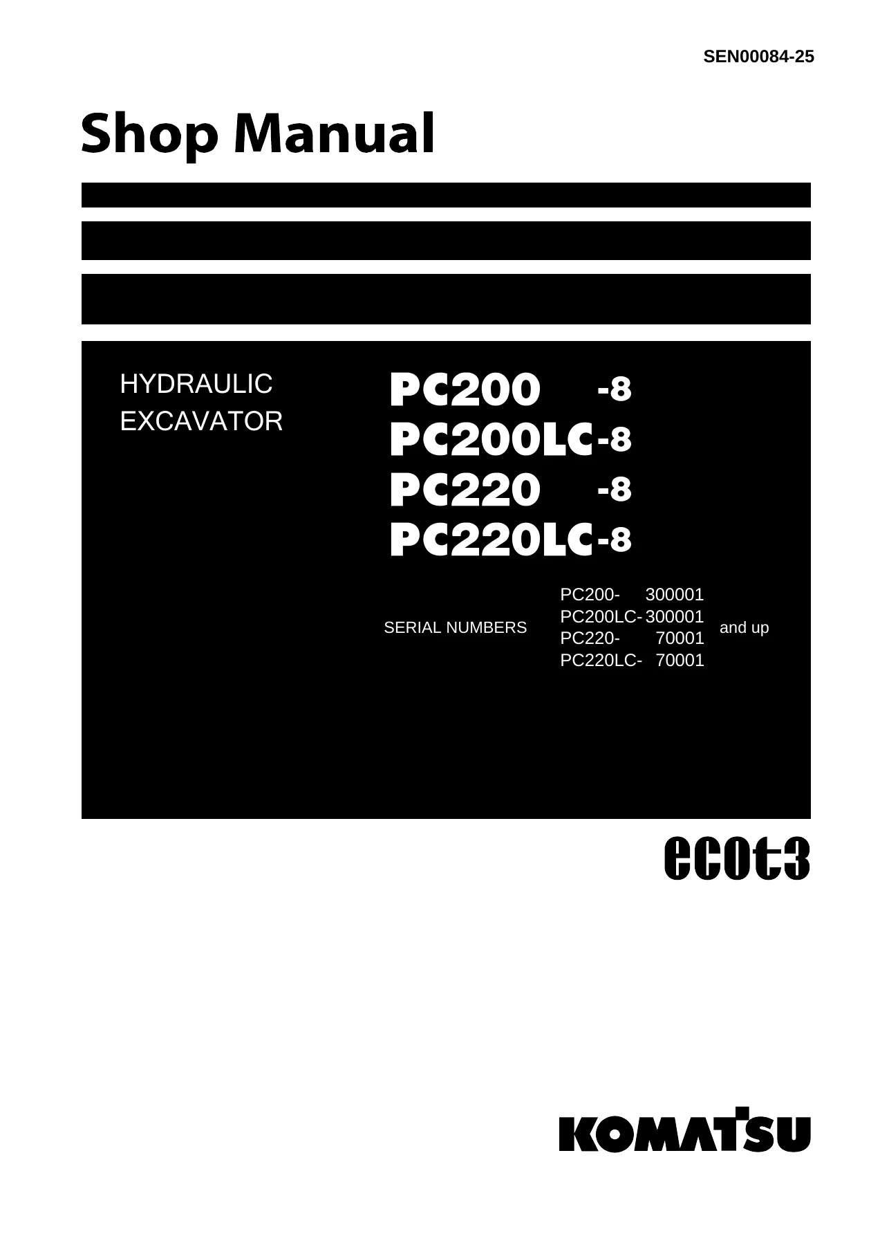
Komatsu PC200-8 PC200LC-8 PC220-8 PC220LC-8 Hydraulic Excavator Shop Manual SEN00084-25 PDF
Original price was: $74.95.$49.95Current price is: $49.95.
Complete Komatsu Shop Manual SEN00084-25 for PC200-8, PC200LC-8, PC220-8 and PC220LC-8 hydraulic excavators. Covers specifications, structure and function, standard values, testing and adjusting, troubleshooting, disassembly and assembly, plus hydraulic and electrical diagrams.
Description
Komatsu PC200-8, PC200LC-8, PC220-8, PC220LC-8 Shop Manual — SEN00084-25
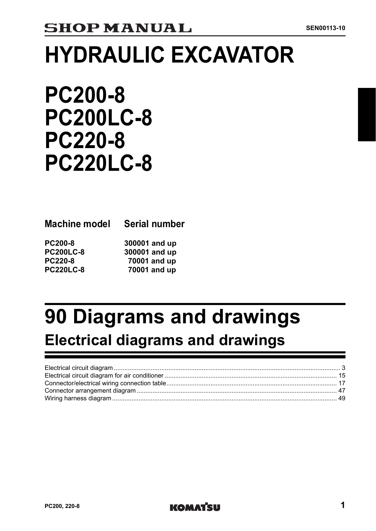
This is the complete Komatsu Shop Manual for the PC200-8, PC200LC-8, PC220-8 and PC220LC-8 hydraulic excavators, issued under document number SEN00084-25. It is the full workshop reference used for specification checks, maintenance standards, testing and adjusting, troubleshooting, disassembly and assembly, and hydraulic and electrical diagrams for these four machine variants. The manual covers PC200-8 and PC200LC-8 machines from serial number 300001 and up, and PC220-8 and PC220LC-8 machines from serial number 70001 and up.
File Details
- Manual type: Shop Manual (workshop service and repair reference)
- Brand: Komatsu
- Models covered: PC200-8, PC200LC-8, PC220-8, PC220LC-8
- Document number: SEN00084-25
- Language: English
- File format: PDF
- Page count: 1,364 pages
- Engine fitted: SAA6D107E-1 (per specification section)
Chapters Covered
- 00 Index and foreword
- 01 Specification
- 10 Structure, function and maintenance standard
- 20 Standard value table
- 30 Testing and adjusting
- 40 Troubleshooting
- 50 Disassembly and assembly
- 90 Diagrams and drawings
00 — Index and Foreword
This opening section lays out how the manual is organised, the filing method for the complete set, the shop manual composition list with form numbers, and the safety notice that applies throughout the workshop. It explains how to read the shop manual, the symbols used for safety, caution, weight, tightening torque, coating, oil and drain points, and the units used in the text. It also covers the handling of electric equipment, hydraulic components, connectors, and the standard tightening torque tables together with the conversion tables used in later sections.
01 — Specification
The specification chapter provides the machine dimension drawings, working range diagrams, full specifications and a weight table for the PC200-8, PC200LC-8, PC220-8 and PC220LC-8. It lists bucket capacity, operating weight, digging depths and reach, swing speed, travel speeds, gradability, ground pressure, engine ratings, hydraulic pump delivery and set pressures, control valve configuration, hydraulic motor and cylinder data, and the table of fuel, coolant and lubricants with refill capacities.
10 — Structure, Function and Maintenance Standard
This chapter explains the structure, function and maintenance standard values for each major assembly. It covers the engine and cooling system, power train, final drive, swing machinery and swing circle, undercarriage and frame, the hydraulic system in three parts (equipment layout, hydraulic pump, control valve and CLSS, swing motor, centre swivel joint, travel motor, PPC valves, solenoid valves, accumulators, anti-drop valves, return oil filter, attachment circuit selector valve and hydraulic cylinders), the work equipment, the cab and its attachments, and the electrical system including engine control, electrical control system, monitor system, sensors and KOMTRAX. Maintenance standard tables list standard clearance, clearance limit, repair limit, interference and remedies for each component.
20 — Standard Value Table
The standard value table section provides the standard service values for engine related parts and chassis related parts. It includes engine speed values, intake pressure, exhaust gas colour, valve clearance, compression pressure, blow-by pressure, engine oil pressure, fan belt and air conditioner compressor belt tension, plus hydraulic pressures for unload, boom, arm, bucket, swing, travel, control circuit source pressure and LS differential pressure, along with swing performance, travel performance, work equipment speed, time lag, internal leakage and pump discharge values.
30 — Testing and Adjusting
This section covers the tools for testing, adjusting and troubleshooting, sketches of special tools, and step-by-step procedures for testing engine speed, intake air pressure, exhaust gas colour, compression pressure, blow-by pressure and engine oil pressure. It includes valve clearance adjustment, fuel system pressure and return tests, air bleeding, fuel circuit leakage checks, air conditioner compressor belt tension, swing circle bearing clearance, track shoe tension, and the inspection and adjustment of oil pressure in the work equipment, swing and travel circuits, control circuit source pressure, pump PC and LS control circuits, solenoid valve output pressure and PPC valve output pressure.
40 — Troubleshooting
The troubleshooting chapter is divided into failure code tables and fuse locations, general information on troubleshooting, troubleshooting by failure code (Parts 1 through 4), troubleshooting of the electrical system (E-mode), troubleshooting of the hydraulic and mechanical system (H-mode), and troubleshooting of the engine (S-mode). It includes the failure code table, fuse box connection table, T-branch box and T-branch adapter table, connector pin number connection table, and detailed diagnostic charts for engine, electrical, hydraulic and mechanical symptoms.
50 — Disassembly and Assembly
This section provides the removal, installation, disassembly and assembly procedures for the major assemblies, along with the special tools, coating materials, tightening torques and capacities needed for each job. It covers the engine and cooling system, power train, undercarriage and frame, hydraulic system, work equipment, cab and its attachments, and the electrical system.
90 — Diagrams and Drawings
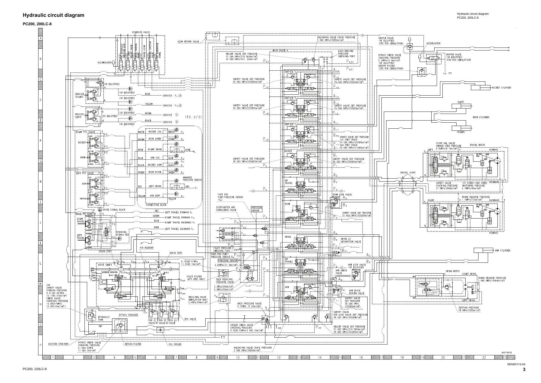
The final chapter contains the hydraulic circuit diagrams for PC200/200LC-8 and PC220/220LC-8, including boom RAISE, swing LEFT, and combined boom RAISE + swing LEFT circuits, plus the electrical circuit diagram, air conditioner electrical circuit, connector and electrical wiring connection table, connector arrangement diagram and wiring harness diagram.
What This Shop Manual Enables You to Do
With the Komatsu PC200-8, PC200LC-8, PC220-8 and PC220LC-8 Shop Manual SEN00084-25 on hand, a technician can carry out the full range of workshop tasks on these excavators: checking and adjusting engine speed, valve clearance, compression pressure, oil pressure, and hydraulic circuit pressures; diagnosing electrical, hydraulic and mechanical faults using the failure code tables and E-mode, H-mode and S-mode charts; removing and installing the engine, hydraulic pump, control valve, swing motor, travel motor, final drive, cylinders and work equipment; and reassembling components to the correct standard clearances, interference limits and tightening torques.
The manual gives the exact specifications and standard values needed to judge whether a component is within service limits, which helps avoid guesswork during repairs. It also provides the wiring and hydraulic circuit diagrams required for tracing faults through the machine’s electrical and hydraulic systems, and the connector pin number tables needed for testing at the harness.
IMAGES PREVIEW
This Komatsu PC200-8, PC200LC-8, PC220-8, PC220LC-8 Shop Manual is delivered as an instant PDF download after payment. No shipping is involved, the file can be stored on a computer, tablet or phone, and individual pages or sections can be printed for use in the workshop.
Reviews
There are no reviews yet.