
Komatsu PC300-8 PC300LC-8 PC350-8 PC350LC-8 Hydraulic Excavator Shop Manual SEN01983-07 PDF
Original price was: $63.95.$39.95Current price is: $39.95.
Complete Komatsu Shop Manual for PC300-8, PC300LC-8, PC350-8 and PC350LC-8 hydraulic excavators (serial 60001 and up). 1,025 pages covering engine, hydraulics, undercarriage, electrical, troubleshooting, disassembly and assembly. Instant PDF download.
Description
Komatsu PC300-8 / PC300LC-8 / PC350-8 / PC350LC-8 Shop Manual — SEN01983-07
This is the complete Komatsu shop manual for the PC300-8, PC300LC-8, PC350-8 and PC350LC-8 hydraulic excavators, serial number 60001 and up. It is the full multi-section document — 1,025 pages — containing the specification sheets, structure and function descriptions, maintenance standards, standard value tables, testing and adjusting procedures, troubleshooting guides (by failure code, by electrical system, by hydraulic and mechanical system, and by engine), complete disassembly and assembly instructions, plus hydraulic and electrical diagrams. Everything a technician or workshop needs to service this machine is in this one PDF.
File Details
- Manual type: Shop Manual (Service / Repair Manual)
- Brand: Komatsu
- Models covered: PC300-8, PC300LC-8, PC350-8, PC350LC-8
- Serial numbers: 60001 and up
- Engine: SAA6D114E (SAA6D114E-3)
- Language: English
- Page count: 1,025
- File format: PDF
- Document number: SEN01983-07
- Publication dates: 2007–2009 (individual form numbers revised and reissued)
Chapters Covered
The manual is organised into the following top-level sections, each supplied as a separate form number bundled into this shop manual:
- 00 Index and foreword
- 01 Specification
- 10 Structure, function and maintenance standard
- 20 Standard value table
- 30 Testing and adjusting
- 40 Troubleshooting
- 50 Disassembly and assembly
- 90 Diagrams and drawings
00 Index and Foreword
The opening section contains the manual composition list, safety notices (general precautions, preparation for work, precautions during work, sling work and signs, mobile crane and overhead hoist precautions), how to read the shop manual, maintenance standard terms (standard size and tolerance, standard clearance and standard value, standard interference, repair limit, clearance limit, interference limit), handling of electric equipment and hydraulic components, connector handling for engines (slide lock, pull lock, push lock, turn-housing type), how to read electric wire codes and colour codes, precautions for disassembly and assembly, push-pull coupler procedures, standard tightening torque tables, and a conversion table. This is the reference material every technician should read before starting work.
01 Specification
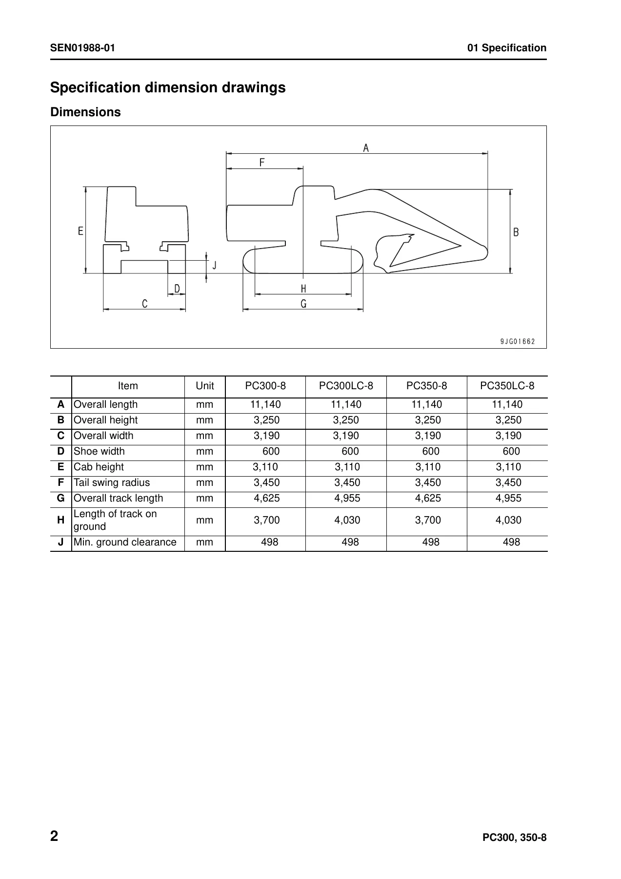
Contains the specification dimension drawings and dimension tables, working range diagrams (max. digging reach, digging depth, digging height, dumping height), full specifications tables for PC300-8, PC300LC-8, PC350-8 and PC350LC-8, weight tables for major components, and the table of fuel, coolant and lubricants. Includes flywheel horsepower, max. torque, high/low idle speeds, hydraulic pump delivery, set pressure, control valve, travel motor, swing motor and cylinder details.
10 Structure, Function and Maintenance Standard
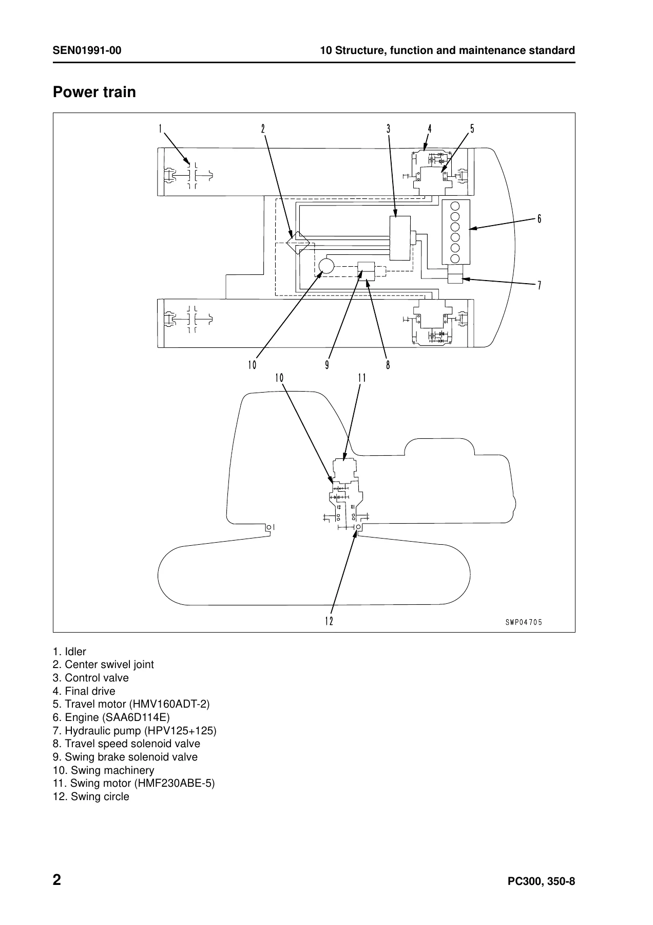
This is the largest section and is split into multiple form numbers: Engine and cooling system (drive plate, damper assembly, radiator, oil cooler, aftercooler); Power train (swing circle, swing machinery, final drive, sprocket); Undercarriage and frame (track frame, recoil spring, idler, carrier roller, track roller, track shoe, triple grouser shoe); Hydraulic system, Part 1 (hydraulic equipment layout, hydraulic tank and filter, hydraulic pump HPV125+125 with LS valve, PC valve, LS-EPC valve, PC-EPC valve, variable volume valve); Hydraulic system, Part 2 (control valve, CLSS, unload valve, LS select valve, self pressure reducing valve, travel junction valve, lift check valve, main relief valve, 2-stage safety-suction valve, variable pressure compensation valve, attachment circuit selector valve, hydraulic drift prevention valve); Hydraulic system, Part 3 (PPC valve, work equipment and swing PPC valve, travel PPC valve, service PPC valve with EPC valve, solenoid valve, PPC accumulator, return oil filter, center swivel joint, travel motor HMV160ADT-2, swing motor KMF230ABE-5, swing holding brake, reverse prevention valve, hydraulic cylinder); Work equipment (dimensions of components); Cab and its attachments (air conditioner piping); and Electrical system (engine control, electronic control system, monitor system, sensor, KOMTRAX system). Each component is illustrated with cutaway and exploded drawings, and the maintenance standard values are given for wear limits and clearances.
20 Standard Value Table
Provides the standard service value tables for engine-related parts and chassis-related parts. Includes engine speed (high idle, low idle, rated), intake pressure, exhaust gas colour, valve clearance, compression pressure, blow-by pressure, engine oil pressure, oil temperature, fan belt tension, air compressor belt tension, hydraulic pressures (unload, boom relief, arm relief, bucket relief, swing relief, travel relief), control circuit source pressure, LS differential pressure, PPC valve output pressure, swing brake angle, time taken to swing, hydraulic drift of swing, leakage from swing motor, travel speeds (Lo/Mi/Hi), travel deviation, hydraulic drift of travel, travel motor leakage, work equipment drift, work equipment speed, time lag, internal leakage, centre swivel joint leakage, and performance in compound operation. This is the reference data used during testing, adjusting and troubleshooting.
30 Testing and Adjusting
Part 1 covers tools for testing, adjusting and troubleshooting, sketches of special tools, testing engine speed, testing air boost pressure, testing exhaust gas colour, adjusting valve clearance, testing compression pressure, testing blow-by pressure, testing engine oil pressure, testing fuel pressure, handling during cylinder cut-out operation, handling during no injection cranking, testing fuel return rate and leakage, bleeding air from fuel circuit, checking fuel circuit for leakage, testing and adjusting air compressor belt tension, replacing fan belt, replacing alternator belt, testing clearance in swing circle bearings, testing and adjusting track shoe tension, testing and adjusting oil pressure in work equipment/swing/travel circuits, testing and adjusting control circuit oil pressure, testing and adjusting pump PC control circuit oil pressure, testing and adjusting pump LS control circuit oil pressure, testing solenoid valve output pressure, testing PPC valve output pressure, adjusting play of work equipment and swing PPC valves, inspecting locations of hydraulic drift, releasing remaining pressure in hydraulic circuit, testing oil leakage amount, bleeding air from various parts, and diode inspection procedures.
Part 2 covers special functions of the machine monitor, including the operator mode and the service mode, monitoring, abnormality record, maintenance record, maintenance mode change, phone number entry, default settings, adjustment of pump absorption torque, low speed setting, attachment flow adjustment, cylinder cut-out, no injection, fuel consumption, KOMTRAX settings and service message display.
Part 3 covers handling the voltage circuit of the engine controller, preparation work for troubleshooting of the electrical system (machine monitor, engine controller, pump controller, KOMTRAX communication module, atmospheric pressure sensor, engine Ne speed sensor, engine Bkup speed sensor, engine oil pressure switch, boost pressure and temperature sensor, supply pump IMV solenoid, electric priming pump, water-in-fuel sensor, common rail pressure sensor, engine coolant temperature sensor), procedure for testing diodes, and Pm clinic service check sheets with engine, work equipment speed, hydraulic drift and hydraulic circuit checks.
40 Troubleshooting
This section contains the failure code table and fuse locations, general information on troubleshooting (points to remember, sequence of events, checks before troubleshooting, classification, information in the troubleshooting table, connection table for connector pin numbers, T-branch box and T-branch adapter table), troubleshooting by failure code in three parts (covering codes from 989L00 through DY2EKB, including engine controller, air cleaner, charge voltage, engine oil pressure, coolant temperature, common rail pressure, injectors, battery, sensor supply, CAN, wiper, washer, camera and KOMTRAX codes), troubleshooting of the electrical system (E-mode) with 31 symptom-based flows, troubleshooting of the hydraulic and mechanical system (H-mode) with 28 symptom-based flows, and troubleshooting of the engine (S-mode) with 16 symptom-based flows.
50 Disassembly and Assembly
Covers general information on disassembly and assembly (how to read the manual, coating materials list, special tool list, sketches of special tools), then goes through the removal, installation, disassembly and assembly of the fuel supply pump, engine front seal, engine rear seal, cylinder head, radiator, hydraulic oil cooler, aftercooler, engine and hydraulic pump assembly, final drive, swing motor and swing machinery, swing circle, carrier roller, track roller, idler, recoil spring, sprocket, track shoe, revolving frame, counterweight, centre swivel joint, hydraulic tank, control valve, hydraulic pump, oil seal in hydraulic pump input shaft, work equipment PPC valve, travel PPC valve, hydraulic cylinder, work equipment assembly, operator’s cab, operator cab glass, front window, floor frame, air conditioner unit, KOMTRAX communication modem, monitor, pump controller and engine controller. Torque values, coating materials, oil capacities and special tools are called out for each procedure.
90 Diagrams and Drawings
Includes the full hydraulic circuit diagram and the complete electrical circuit diagram (5 sheets), plus a connector list and stereogram showing connector numbers, types, pin counts, component names and arrangement drawings.
What This Manual Lets You Do
With this Komatsu PC300-8 / PC300LC-8 / PC350-8 / PC350LC-8 shop manual in hand, you can diagnose and repair the machine the way the workshop intended. You get the factory procedures for pulling the hydraulic pump, control valve, travel motor, swing motor, final drive and cylinders; the set pressures and torque values needed to put everything back correctly; the standard service values for judging wear; and the failure-code troubleshooting trees that walk you from a displayed code to the root cause instead of guessing and swapping parts.
The manual covers all four model variants in one document, so you do not need separate books for the standard and long-undercarriage versions. The specification tables, weight tables and fuel/lubricant charts mean you also have the data for lifting, transport and routine servicing.
IMAGES PREVIEW
Delivered as an instant PDF download — no shipping, no waiting. Read it on a laptop, tablet or phone in the workshop, or print the pages you need for the job. The complete 1,025-page Komatsu shop manual for the PC300-8, PC300LC-8, PC350-8 and PC350LC-8 is one of the most useful references you can keep on the service truck.
Reviews
There are no reviews yet.