Description
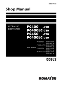
Komatsu PC400-7E0 PC450-7E0 Excavator Shop Manual
This Komatsu PC400-7E0 PC450-7E0 Excavator Shop Manual (Form No. SEN03578-01) is the complete workshop reference for the PC400-7E0, PC400LC-7E0, PC450-7E0 and PC450LC-7E0 hydraulic excavators. It brings together specifications, structure and function, standard value tables, testing and adjusting procedures, troubleshooting by failure code, disassembly and assembly instructions, and hydraulic and electrical diagrams in one document. Whether you are servicing the SAA6D125E-5 engine, diagnosing a hydraulic fault, or rebuilding a final drive, this manual provides the procedures and values needed to carry out the work correctly.
File Details
- Manual Type: Shop Manual
- Brand: Komatsu
- Models Covered: PC400-7E0, PC400LC-7E0, PC450-7E0, PC450LC-7E0
- Language: English
- Page Count: Approximately 1,006 pages
- File Format: PDF
- Form Number: SEN03578-01
- Date: 2008
Chapters Covered
- 00 Index and Foreword β Organization list of the shop manual, table of contents, safety notice, how to read the shop manual, explanation of terms for maintenance standard, handling of electric equipment and hydraulic components, handling of connectors newly used for engines, how to read electric wire code, precautions when carrying out operation, method of disassembling and connecting push-pull type coupler, standard tightening torque table, conversion table
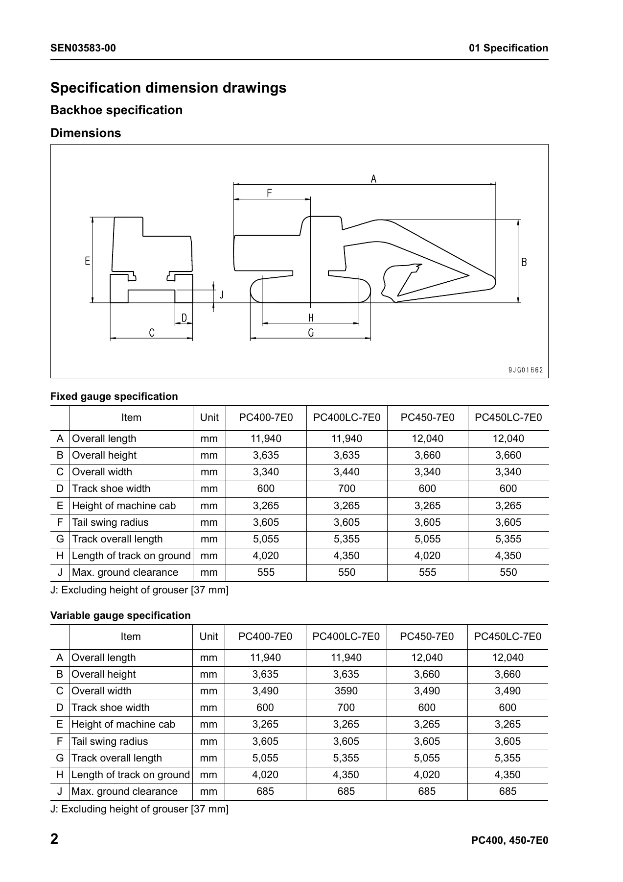
- 01 Specification β Specification dimension drawings, specifications, weight table, table of fuel, coolant and lubricants
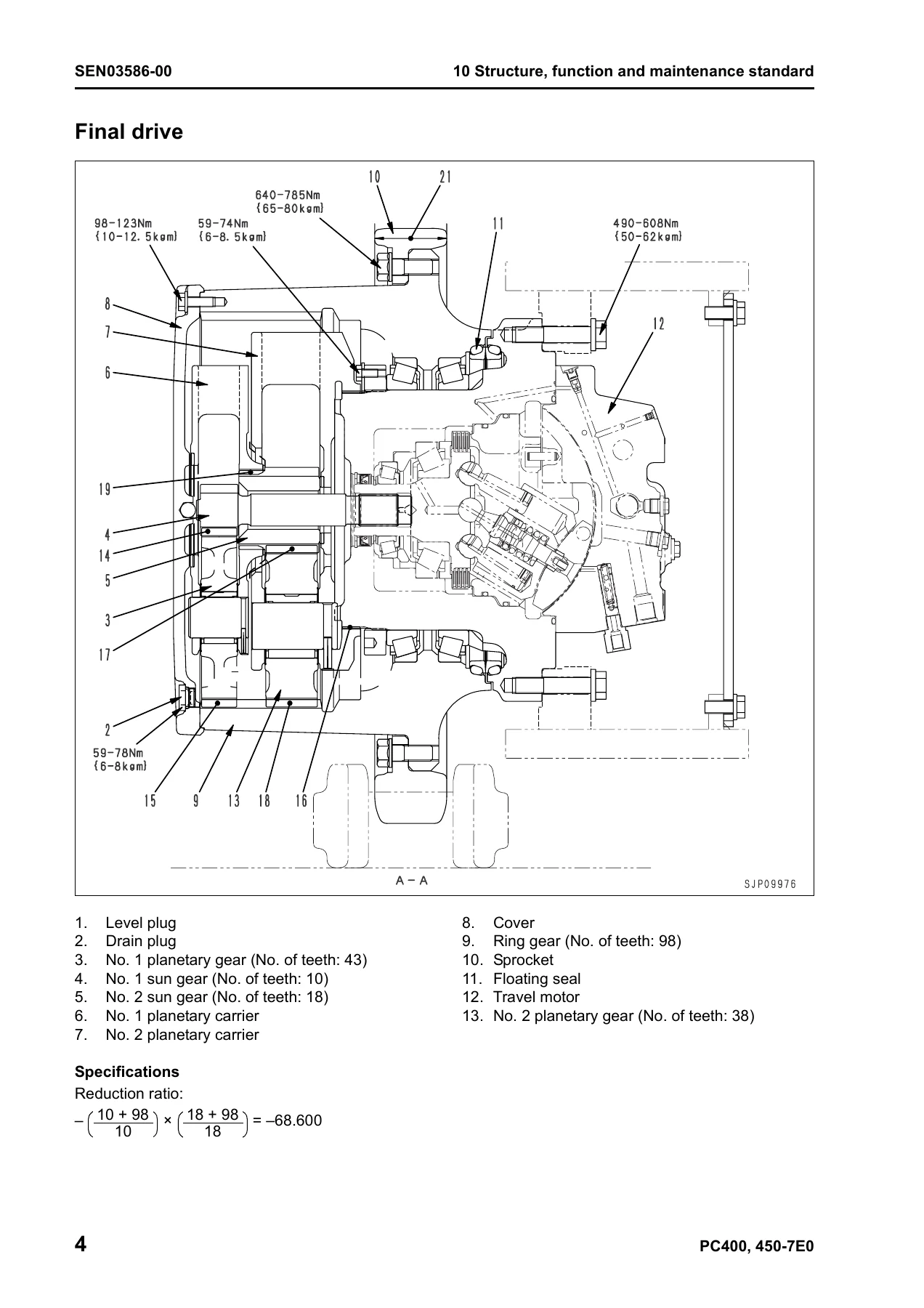
- 10 Structure, Function and Maintenance Standard β Engine and cooling system (engine related parts, radiator, oil cooler and aftercooler), Power train (power train, final drive, sprocket, swing machinery, swing circle), Undercarriage and frame (track frame and recoil spring, idler, carrier roller, track roller, track shoe), Hydraulic system Part 1 (hydraulic equipment layout drawing, hydraulic tank and filter, hydraulic pump), Hydraulic system Part 2 (control valve, CLSS, functions and operation by valve, merge-divider valve, attachment circuit selector valve, holding valve), Hydraulic system Part 3 (valve control, PPC valve, solenoid valve, PPC accumulator, return oil filter, center swivel joint, travel motor, swing motor, hydraulic cylinder), Work equipment, Cab and its attachments, Electrical system (engine control, electronic control system, monitor system, sensor, KOMTRAX terminal system)
- 20 Standard Value Table β Standard value table for engine related parts, standard value table for chassis related parts (backhoe specification), standard value table for chassis related parts (loading shovel specification)
- 30 Testing and Adjusting β Tools for testing, adjusting and troubleshooting; measuring engine speed; measuring air boost pressure; measuring exhaust temperature; measuring exhaust gas color; adjusting valve clearance; measuring compression pressure; measuring blow-by pressure; measuring engine oil pressure; handling fuel system parts; releasing residual pressure from fuel system; measuring fuel pressure; handling during cylinder cut-out operation; handling during no injection cranking operation; measuring fuel return rate and leakage; bleeding air from fuel circuit; checking fuel circuit for leakage; checking and adjusting fan belt and alternator belt tension; checking and adjusting air conditioner compressor belt tension; measuring swing circle bearing clearance; checking and adjusting track shoe tension; measuring and adjusting oil pressure in work equipment, swing, and travel circuits; measuring control circuit basic pressure; checking and adjusting pump PC control circuit oil pressure; checking and adjusting pump LS control circuit oil pressure; measuring solenoid valve output pressure; measuring PPC valve output pressure; adjusting play of work equipment and swing PPC valves; inspecting locations of hydraulic drift of work equipment; releasing residual pressure from hydraulic circuit; measuring oil leakage amount; bleeding air from various parts; special functions of machine monitor; procedure for turning on KOMTRAX terminal; indication by KOMTRAX terminal lamps; handling voltage circuit of engine controller; preparation work for troubleshooting of electrical system; procedure for testing diodes; Pm clinic service; undercarriage troubleshooting report
- 40 Troubleshooting β Failure code table and fuse locations; information related to troubleshooting (points to remember, sequence of events, checks before troubleshooting, classification and troubleshooting steps, information in troubleshooting table, connection table for connector pin numbers, T-branch box and T-branch adapter table); Troubleshooting by failure code (Display of code) Part 1, Part 2, Part 3; Troubleshooting of electrical system (E-mode); Troubleshooting of hydraulic and mechanical system (H-mode); Troubleshooting of engine (S-mode)
- 50 Disassembly and Assembly β General information on disassembly and assembly (how to read this manual, coating materials list, special tools list, sketches of special tools); Engine and cooling system (removal and installation of fuel supply pump assembly, fuel injector assembly, engine front seal, engine rear seal, cylinder head assembly, radiator assembly, hydraulic oil cooler assembly, aftercooler assembly, engine and hydraulic oil pump assembly); Power train (final drive assembly, swing motor and swing machinery assembly, swing circle assembly); Undercarriage and frame (carrier roller assembly, track roller assembly, idler assembly, recoil spring assembly, sprocket, track shoe assembly, revolving frame assembly, counterweight assembly); Hydraulic system (center swivel joint assembly, hydraulic tank assembly, control valve assembly, hydraulic pump assembly, oil seal in hydraulic pump input shaft, work equipment PPC valve assembly, travel PPC valve assembly, hydraulic cylinder assembly); Work equipment; Cab and its attachments (operator’s cab, operator’s cab glass, front window assembly); Electrical system (air conditioner unit assembly, KOMTRAX terminal assembly, monitor assembly, pump controller)
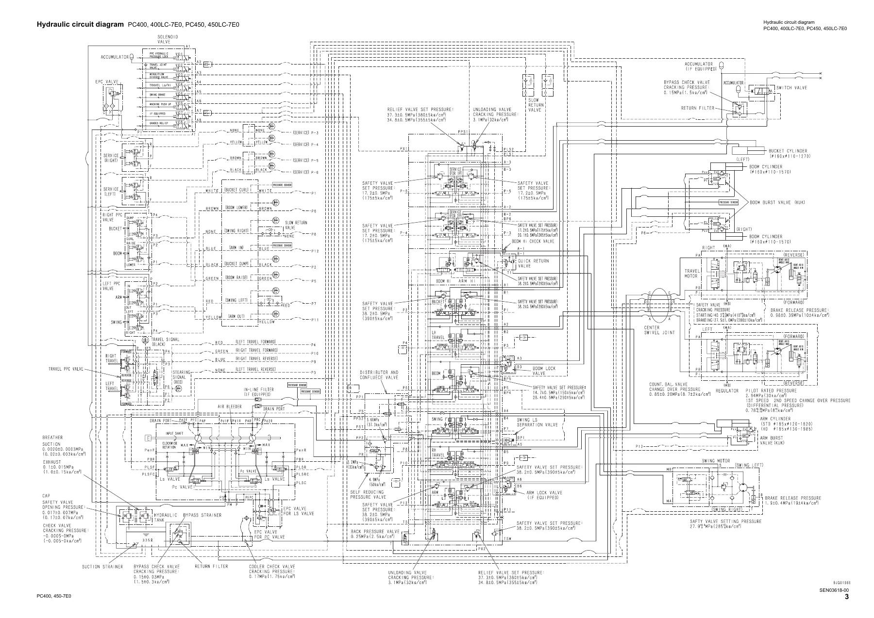
- 90 Diagrams and Drawings β Hydraulic circuit diagram, electrical circuit diagram, connector arrangement diagram
This Komatsu PC400-7E0 PC450-7E0 Excavator Shop Manual goes well beyond a basic service guide. The structure, function and maintenance standard chapter explains how each major component works and what the maintenance criteria are, serving as reference material for troubleshooting. The standard value table gives the specifications and judgement criteria needed to evaluate parts during testing and adjusting. The testing and adjusting chapter provides the measuring instruments, methods, and adjustment procedures for the engine, hydraulic system, swing, travel, and work equipment circuits. The troubleshooting section is divided by failure mode and includes failure code tables, electrical system diagnostics, hydraulic and mechanical system diagnostics, and engine troubleshooting. The disassembly and assembly section covers the special tools, removal, installation, disassembly, and assembly procedures for the major components, along with tightening torques and coating materials. The diagrams section rounds out the manual with hydraulic circuit diagrams and electrical circuit diagrams.
For anyone maintaining, repairing, or rebuilding a PC400-7E0, PC400LC-7E0, PC450-7E0, or PC450LC-7E0 excavator, this Komatsu PC400-7E0 PC450-7E0 Excavator Shop Manual provides the complete technical foundation. The engine coverage alone makes it valuable, but the hydraulic system and electrical system sections are equally important for diagnosing the complex issues these machines can develop. The disassembly and assembly procedures help ensure that components are removed, inspected, and reinstalled correctly, with the proper tools and torque values. The troubleshooting tables and failure code diagnostics can save hours of guesswork by pointing directly at the affected circuit or component.
What This Manual Enables You to Do
- Identify and resolve Komatsu PC400-7E0 PC450-7E0 excavator fault codes using the detailed failure code troubleshooting tables covering engine, electrical, hydraulic, and mechanical systems.
- Measure, test, and adjust the engine and hydraulic systems using the procedures and standard values given for the SAA6D125E-5 engine and the closed-center load sensing (CLSS) hydraulic system.
- Disassemble and reassemble major components β final drive, swing machinery, hydraulic pump, control valve, travel motor, swing motor, hydraulic cylinders, and work equipment β using the special tool lists, removal and installation steps, and tightening torques.
- Understand the structure and function of each major system, from the engine and cooling system through the power train, undercarriage, hydraulic system, and electrical system, including the electronic control system, monitor system, and KOMTRAX terminal.
- Perform routine testing and adjusting tasks such as measuring engine speed, boost pressure, exhaust temperature, valve clearance, compression pressure, oil pressure, and hydraulic circuit pressures.
Why the Komatsu PC400-7E0 PC450-7E0 Excavator Shop Manual Matters
Working on a hydraulic excavator without the correct specifications and procedures invites costly mistakes. A hydraulic pressure set incorrectly, a torque value guessed at, or a failure code misdiagnosed can lead to component damage, downtime, and unnecessary parts replacement. This manual provides the values, tolerances, and step-by-step methods that Komatsu specifies for these machines, so the work is done right the first time. The troubleshooting sections are particularly valuable because they walk through the diagnostic logic for the electrical, hydraulic, and mechanical systems, helping to pinpoint the root cause rather than just the symptom.
Complete PDF Bookmark Tree
Complete Bookmarks
The complete bookmarks in the βKomatsu PC400-7E0 PC450-7E0 Excavator Shop Manual – SEN03578-01β are as follows:
COVERp. 1
+00 Index and foreword
+Indexp. 2
Organization list of the shop manualp. 3
Table of contentsp. 5
+Foreword and general informationp. 14
Safety noticep. 15
How to read the shop manualp. 20
Explanation of terms for maintenance standardp. 22
Handling of electric equipment and hydraulic componentp. 24
Handling of connectors newly used for enginesp. 33
How to read electric wire codep. 36
Precautions when carrying out operationp. 39
Method of disassembling and connecting push-pull type couplerp. 42
Standard tightening torque tablep. 45
Conversion tablep. 49
+01 Specification
+Specification and technical datap. 56
Specification dimension drawingsp. 57
Specificationsp. 61
Weight tablep. 67
Table of fuel, coolant and lubricantsp. 71
+10 Structure, function and maintenance standard
+Engine and cooling systemp. 74
Engine related partsp. 75
Radiator, oil cooler and aftercoolerp. 76
+Power trainp. 78
Power trainp. 79
Final drivep. 81
Sprocketp. 83
Swing machineryp. 85
Swing circlep. 87
+Undercarriage and framep. 90
Track frame and recoil springp. 91
Idlerp. 93
Carrier rollerp. 95
Track rollerp. 96
Track shoep. 97
+Hydraulic system, Part 1p. 102
Hydraulic equipment layout drawingp. 103
Hydraulic tank and filterp. 105
Hydraulic pumpp. 107
+Hydraulic system, Part 2p. 132
Control valvep. 133
CLSSp. 157
Functions and operation by valvep. 161
Merge-divider valvep. 178
Attachment circuit selector valvep. 203
Holding valvep. 205
+Hydraulic system, Part 3p. 212
Valve controlp. 213
PPC valvep. 215
Solenoid valvep. 231
PPC accumulatorp. 233
Return oil filterp. 234
Center swivel jointp. 235
Travel motorp. 236
Swing motorp. 248
Hydraulic cylinderp. 257
+Work equipmentp. 262
Work equipmentp. 263
Dimensions of componentsp. 267
+Cab and its attachmentsp. 272
Air conditioner pipingp. 273
+Electrical systemp. 276
Engine controlp. 277
Electronic control systemp. 286
Monitor systemp. 311
Sensorp. 329
KOMTRAX terminal systemp. 332
+20 Standard value table
+Standard service value tablep. 336
Standard value table for engine related partsp. 337
Standard value table for chassis related partsp. 338
Standard value table for chassis related partsp. 347
+30 Testing and adjusting
+Testing and adjusting, Part 1p. 358
Tools for testing, adjusting and troubleshootingp. 360
Measuring engine speedp. 364
Measuring air boost pressurep. 365
Measuring exhaust temperaturep. 366
Measuring exhaust gas colorp. 367
Adjusting valve clearancep. 368
Measuring compression pressurep. 370
Measuring blow-by pressurep. 372
Measuring engine oil pressurep. 373
Handling fuel system partsp. 375
Releasing residual pressure from fuel systemp. 375
Measuring fuel pressurep. 376
Handling during cylinder cut-out operationp. 377
Handling during no injection cranking operationp. 377
Measuring fuel return rate and leakagep. 378
Bleeding air from fuel circuitp. 381
Checking fuel circuit for leakagep. 382
Checking and adjusting fan belt and alternator belt tensionp. 383
Checking and adjusting air conditioner compressor belt tensionp. 384
Measuring swing circle bearing clearancep. 385
Checking and adjusting track shoe tensionp. 386
Measuring and adjusting oil pressure in work equipment, swing, and travel circuitsp. 387
Measuring control circuit basic pressurep. 391
Checking and adjusting pump PC control circuit oil pressurep. 392
Checking and adjusting pump LS control circuit oil pressurep. 395
Measuring solenoid valve output pressurep. 400
Measuring PPC valve output pressurep. 403
Adjusting play of work equipment and swing PPC valvesp. 404
Inspecting locations of hydraulic drift of work equipmentp. 405
Releasing residual pressure from hydraulic circuitp. 407
Measuring oil leakage amountp. 408
Bleeding air from various partsp. 411
+Testing and adjusting, Part 2p. 416
Special functions of machine monitorp. 417
+Testing and adjusting, Part 3p. 446
Procedure for turning on KOMTRAX terminalp. 447
Indication by KOMTRAX terminal lampsp. 450
Handling voltage circuit of engine controllerp. 453
Preparation work for troubleshooting of electrical systemp. 454
Procedure for testing diodesp. 459
Pm clinic servicep. 460
Undercarriage troubleshooting reportp. 467
+40 Troubleshooting
+Failure code table and fuse locationsp. 470
Failure codes tablep. 471
Before carrying out troubleshooting when failure code is displayedp. 475
+Information related to troubleshootingp. 480
Points to remember when troubleshootingp. 481
Sequence of events in troubleshootingp. 482
Checks before troubleshootingp. 483
Classification and troubleshooting stepsp. 484
Information in troubleshooting tablep. 485
Connection table for connector pin numbersp. 490
T- branch box and T- branch adapter tablep. 526
+Troubleshooting by failure code (Display of code), Part 1p. 530
Failure code [A000N1] Eng. Hi Out of Stdp. 532
Failure code [AA10NX] Aircleaner Cloggingp. 533
Failure code [AB00KE] Charge Voltage Lowp. 535
Failure code [B@BAZG] Eng Oil Press. Lowp. 537
Failure code [B@BAZK] Eng. Oil Level Lowp. 539
Failure code [B@BCNS] Eng. Water Overheatp. 541
Failure code [B@BCZK] Eng. Water Lvl Lowp. 543
Failure code [B@HANS] Hydr. Oil Overheatp. 545
Failure code [CA111] ECM Critical Internal Failurep. 547
Failure code [CA115] Eng Ne and Bkup Speed Sens Errorp. 549
Failure code [CA122] Chg Air Press Sensor High Errorp. 550
Failure code [CA123] Chg Air Press Sensor Low Errorp. 552
Failure code [CA131] Throttle Sensor High Errorp. 553
Failure code [CA132] Throttle Sensor Low Errorp. 555
Failure code [CA135] Eng Oil Press Sensor High Errorp. 556
Failure code [CA141] Eng Oil Press Sensor Low Errorp. 558
Failure code [CA144] Coolant Temp Sens High Errorp. 559
Failure code [CA145] Coolant Temp Sens Low Errorp. 561
Failure code [CA153] Chg Air Temp Sensor High Errorp. 562
Failure code [CA154] Chg Air Temp Sensor Low Errorp. 564
Failure code [CA187] Sens Supply 2 Volt Low Errorp. 564
Failure code [CA221] Ambient Press Sens High Errorp. 565
Failure code [CA222] Ambient Press Sens Low Errorp. 567
Failure code [CA227] Sens Supply 2 Volt High Errorp. 568
Failure code [CA234] Eng Overspeedp. 570
Failure code [CA238] Ne Speed Sens Supply Volt Errorp. 571
Failure code [CA263] Fuel Temp Sensor High Errorp. 573
Failure code [CA265] Fuel Temp Sensor Low Errorp. 575
Failure code [CA271] IMV/PCV1 Short Errorp. 576
Failure code [CA272] IMV/PCV1 Open Errorp. 577
Failure code [CA273] PCV2 Short Errorp. 579
Failure code [CA274] PCV2 Open Errorp. 580
Failure code [CA322] Inj #1 Open/Short Errorp. 581
Failure code [CA323] Inj #5 Open/Short Errorp. 583
Failure code [CA324] Inj #3 Open/Short Errorp. 585
Failure code [CA325] Inj #6 Open/Short Errorp. 587
Failure code [CA331] Inj #2 Open/Short Errorp. 589
Failure code [CA332] Inj #4 Open/Short Errorp. 591
+Troubleshooting by failure code (Display of code), Part 2p. 594
Failure code [CA342] Calibration Code Incompatibilityp. 596
Failure code [CA351] Injectors Drive Circuit Errorp. 597
Failure code [CA352] Sens Supply 1 Volt Low Errorp. 599
Failure code [CA386] Sens Supply 1 Volt High Errorp. 601
Failure code [CA441] Battery Voltage Low Errorp. 603
Failure code [CA442] Battery Voltage High Errorp. 603
Failure code [CA449] Rail Press Very High Errorp. 604
Failure code [CA451] Rail Press Sensor High Errorp. 605
Failure code [CA452] Rail Press Sensor Low Errorp. 607
Failure code [CA553] Rail Press High Errorp. 607
Failure code [CA554] Rail Press Sensor In Range Errorp. 608
Failure code [CA559] Rail Press Low Errorp. 609
Failure code [CA689] Eng Ne Speed Sensor Errorp. 613
Failure code [CA731] Eng Bkup Speed Sens Phase Errorp. 615
Failure code [CA757] All Persistent Data Lost Errorp. 616
Failure code [CA778] Eng Bkup Speed Sensor Errorp. 617
Failure code [CA1228] EGR Valve Servo Error 1p. 619
Failure code [CA1625] EGR Valve Servo Error 2p. 620
Failure code [CA1633] KOMNET Datalink Timeout Errorp. 621
Failure code [CA2185] Throt Sens Sup Volt High Errorp. 623
Failure code [CA2186] Throt Sens Sup Volt Low Errorp. 625
Failure code [CA2249] Rail Press Very Low Errorp. 626
Failure code [CA2271] EGR Valve Lift Sens High Errorp. 627
Failure code [CA2272] EGR Valve Lift Sens Low Errorp. 629
Failure code [CA2351] EGR Valve Sol Current High Errorp. 631
Failure code [CA2352] EGR Valve Sol Current Low Errorp. 633
Failure code [CA2555] Grid Htr Relay Volt Low Errorp. 634
Failure code [CA2556] Grid Htr Relay Volt High Errorp. 635
Failure code [D110KB] Battery Relay Drive S/Cp. 637
Failure code [D196KA] Service Return Relay Disc.p. 639
Failure code [D196KB] Service Return Relay S/Cp. 641
Failure code [DA25KP] Press. Sensor Power Abnormalityp. 643
Failure code [DA80MA] Auto. Lub. Abnormal.p. 645
+Troubleshooting by failure code (Display of code), Part 3p. 648
Failure code [DA2RMC] Pump Comm. Abnormalityp. 651
Failure code [DA2SKQ] Model Selection Abnormalityp. 653
Failure code [DAFRMC] Monitor Comm. Abnormalityp. 655
Failure code [DHPAMA] F Pump P. Sensor Abnormalityp. 657
Failure code [DHPBMA] R Pump P. Sensor Abnormalityp. 659
Failure code [DHS3MA] Arm Curl PPC Sen. Abnormalityp. 661
Failure code [DHS4MA] Bucket Curl PPC Sen. Abnormalityp. 663
Failure code [DW43KA] Travel Speed Sol. Disc.p. 665
Failure code [DW43KB] Travel Speed Sol. S/Cp. 667
Failure code [DW45KA] Swing Brake Sol. Disc.p. 669
Failure code [DW45KB] Swing Brake Sol. S/Cp. 673
Failure code [DW91KA] Travel Junction Sol. Disc.p. 675
Failure code [DW91KB] Travel Junction Sol. S/Cp. 677
Failure code [DWJ0KA] Merge-divider Sol. Disc.p. 679
Failure code [DWJ0KB] Merge-Divider Sol. S/Cp. 681
Failure code [DWK0KA] 2-stage Relief Sol. Disc.p. 683
Failure code [DWK0KB] 2-stage Relief Sol. S/Cp. 685
Failure code [DXA0KA] PC-EPC Sol. Disc.p. 687
Failure code [DXA0KB] PC-EPC Sol. S/Cp. 689
Failure code [DXE0KA] LS-EPC Sol. Disc.p. 691
Failure code [DXE0KB] LS-EPC Sol. S/Cp. 693
Failure code [DXE4KA] Service Current EPC Disc.p. 695
Failure code [DXE4KB] Service Current EPC S/Cp. 696
Failure code [DY20KA] Wiper Working Abnormalityp. 697
Failure code [DY20MA] Wiper Parking Abnormalityp. 699
Failure code [DY2CKB] Washer Drive S/Cp. 701
Failure code [DY2DKB] Wiper Drive (For) S/Cp. 703
Failure code [DY2EKB] Wiper Drive (Rev) S/Cp. 705
+Troubleshooting of electrical system (E-mode)p. 708
Before carrying out troubleshooting of electrical systemp. 711
Information contained in troubleshooting tablep. 713
E-1 Engine does not startp. 714
E-2 Auto-decelerator does not operatep. 717
E-3 Automatic warming-up does not operatep. 719
E-4 Preheater does not operatep. 721
E-5 All work equipment, swing, and travel mechanism do not movep. 723
E-6 Power maximizing function does not operatep. 725
E-7 Machine monitor does not display at allp. 727
E-8 Machine monitor does not display some itemsp. 729
E-9 Contents of display by machine monitor are different from applicable machinep. 729
E-10 Fuel level monitor was lighted in red while engine runningp. 730
E-11 Engine coolant temperature gauge does not indicate normallyp. 731
E-12 Hydraulic oil temperature gauge does not indicate normallyp. 733
E-13 Fuel level gauge does not operate normallyp. 734
E-14 Swing lock monitor does not indicate normallyp. 735
E-15 When monitor switch is operated, monitor displays nothingp. 737
E-16 Windowshield wiper does not operatep. 739
E-17 Machine push-up function does not operate normallyp. 743
E-18 Monitoring function fails to display βboom RAISEβ normallyp. 745
E-19 Monitoring function fails to display βboom LOWERβ normallyp. 747
E-20 Monitoring function fails to display βarm INβnormallyp. 749
E-21 Monitoring function fails to display βarm OUTβ normallyp. 751
E-22 Monitoring function fails to display βbucket CURLβnormallyp. 753
E-23 Monitoring function fails to display βbucket DUMPβ normallyp. 755
E-24 Monitoring function fails to display βswingβ normallyp. 757
E-25 Monitoring function fails to display βtravelβ normallyp. 759
E-26 Monitoring function fails to display βtravel differential pressureβ normallyp. 761
E-27 Monitoring function fails to display βserviceβ normallyp. 763
E-28 The KOMTRAX system does not operate normallyp. 765
E-29 Air conditioner does not operatep. 767
E-30 Travel alarm does not sound or does not stop soundingp. 769
E-31 Horn does not soundp. 771
+Troubleshooting of hydraulic and mechanical system (H-mode)p. 774
System chart for hydraulic and mechanical systemp. 777
Information contained in troubleshooting tablep. 779
H-1 All work equipment lack power, or travel and swing speeds are slowp. 781
H-2 Engine speed sharply drops or engine stallsp. 783
H-3 No work equipment, swing or travel movep. 784
H-4 Abnormal noise is heard from around hydraulic pumpp. 784
H-5 Auto-decelerator does not workp. 785
H-6 Fine control mode does not function or responds slowp. 785
H-7 Boom moves slowly or lacks powerp. 786
H-8 Arm moves slowly or lacks powerp. 787
H-9 Bucket moves slowly or lacks powerp. 788
H-10 Work equipment does not move in its single operationp. 788
H-11 Work equipment has a bit too fast hydraulic driftp. 789
H-12 Work equipment has big time lagp. 791
H-13 Other work equipment moves when relieving single circuitp. 791
H-14 Power max. switch does not operatep. 791
H-15 Machine push-up function does not operate.p. 792
H-16 In compound operation of work equipment, speed of part loaded more is lowp. 793
H-17 When machine swings and raises boom simultaneously, boom rising speed is lowp. 793
H-18 When machine swings and travels simultaneously, travel speed lowers largelyp. 793
H-19 Machine deviates during travelp. 794
H-20 Travel speed is lowp. 795
H-21 Machine is not steered well or steering power is lowp. 796
H-22 Travel speed does not change or travel speed is low or highp. 797
H-23 Travel system does not move (only one side)p. 798
H-24 Upper structure does not swingp. 799
H-25 Swing acceleration or swing speed is lowp. 801
H-26 Upper structure overruns remarkably when it stops swingingp. 803
H-27 Large shock is made when upper structure stops swingingp. 804
H-28 Large sound is made when upper structure stops swinging.p. 804
H-29 Hydraulic drift of swing is largep. 805
H-30 Attachment circuit is not changedp. 806
H-31 Oil flow in attachment circuit cannot be controlledp. 806
+Troubleshooting of engine (S-mode)p. 808
Method of using troubleshooting chartp. 811
S-1 Starting performance is poorp. 815
S-2 Engine does not startp. 817
S-3 Engine does not pick up smoothlyp. 821
S-4 Engine stops during operationsp. 822
S-5 Engine does not rotate smoothlyp. 823
S-6 Engine lacks output (or lacks power)p. 824
S-7 Exhaust smoke is black (incomplete combustion)p. 825
S-8 Oil consumption is excessive (or exhaust smoke is blue)p. 826
S-9 Oil becomes contaminated quicklyp. 827
S-10 Fuel consumption is excessivep. 828
S-11 Oil is in coolant (or coolant spurts back or coolant level goes down)p. 829
S-12 Oil pressure dropsp. 830
S-13 Oil level rises (Entry of coolant or fuel)p. 831
S-14 Coolant temperature becomes too high (overheating)p. 833
S-15 Abnormal noise is madep. 834
S-16 Vibration is excessivep. 835
+50 Disassembly and assembly
+General information on disassembly and assemblyp. 838
How to read this manualp. 839
Coating materials listp. 841
Special tools listp. 844
Sketches of special toolsp. 848
+Engine and cooling systemp. 854
Removal and installation of fuel supply pump assemblyp. 855
Removal and installation of fuel injector assemblyp. 859
Removal and installation of engine front sealp. 865
Removal and installation of engine rear sealp. 868
Removal and installation of cylinder head assemblyp. 872
Removal and installation of radiator assemblyp. 881
Removal and installation of hydraulic oil cooler assemblyp. 883
Removal and installation of aftercooler assemblyp. 885
Removal and installation of engine and hydraulic oil pump assemblyp. 886
+Power trainp. 894
Removal and installation of final drive assemblyp. 895
Disassembly and assembly of final drive assemblyp. 896
Removal and installation of swing motor and swing machinery assemblyp. 904
Disassembly and assembly of swing motor and swing machinery assemblyp. 905
Removal and installation of swing circle assemblyp. 912
+Undercarriage and framep. 914
Disassembly and assembly of carrier roller assemblyp. 915
Disassembly and assembly of track roller assemblyp. 917
Disassembly and assembly of idler assemblyp. 918
Disassembly and assembly of recoil spring assemblyp. 921
Removal and installation of sprocketp. 923
Expansion and installation of track shoe assemblyp. 924
Removal and installation of revolving frame assemblyp. 926
Removal and installation of counterweight assemblyp. 929
+Hydraulic systemp. 932
Removal and installation of center swivel joint assemblyp. 933
Disassembly and assembly of center swivel joint assemblyp. 935
Removal and installation of hydraulic tank assemblyp. 936
Removal and installation of control valve assemblyp. 938
Disassembly and assembly of control valve assemblyp. 941
Removal and installation of hydraulic pump assemblyp. 945
Removal and installation of oil seal in hydraulic pump input shaftp. 948
Disassembly and assembly of work equipment PPC valve assemblyp. 949
Disassembly and assembly of travel PPC valve assemblyp. 951
Disassembly and assembly of hydraulic cylinder assemblyp. 953
+Work equipmentp. 960
Removal and installation of work equipment assemblyp. 961
+Cab and its attachmentsp. 966
Removal and installation of operatorβs cabp. 967
Removal and installation of operatorβs cab glass (stuck glass)p. 970
Removal and installation of front window assemblyp. 980
+Electrical systemp. 988
Removal and installation of air conditioner unit assemblyp. 989
Removal and Installation of KOMTRAX terminal assemblyp. 991
Removal and installation of monitor assemblyp. 992
Removal and installation of pump controllerp. 993
+90 Diagrams and drawings
+Hydraulic diagrams and drawingsp. 996
Hydraulic circuit diagramp. 998
+Electrical diagrams and drawingsp. 1001
Electrical circuit diagramp. 1003
Connector arrangement diagramp. 1004
The Komatsu PC400-7E0 PC450-7E0 Excavator Shop Manual is delivered as an instant PDF download after payment. There is no shipping, no waiting for a physical book, and no restrictions on where or how you use it. You can access it on any device β laptop, tablet, or smartphone β and print the pages you need for the workshop. The searchable text makes it quick to locate a specific specification, failure code, or procedure, so you spend less time flipping through pages and more time getting the machine back in service.
Reviews
There are no reviews yet.