Description
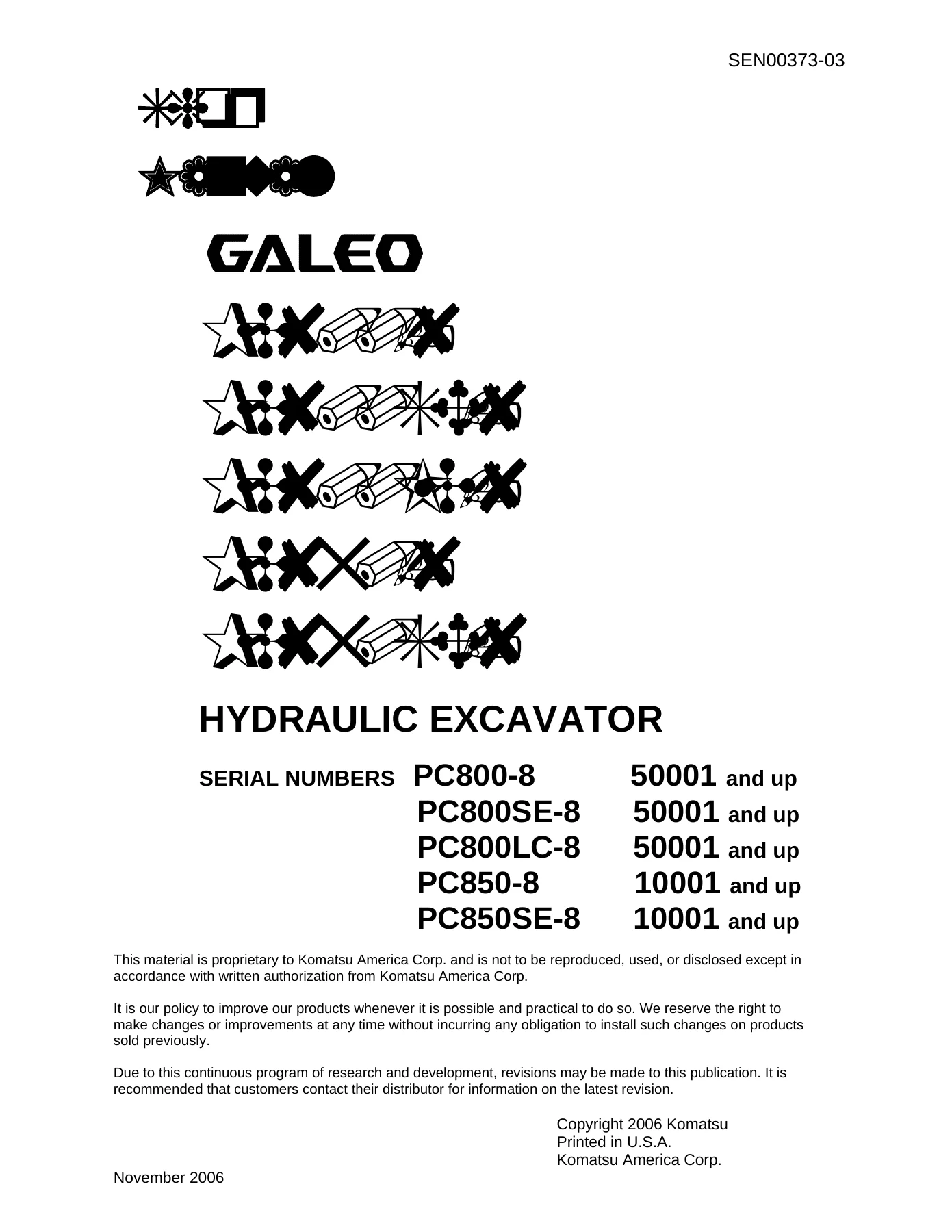
Komatsu PC800-8, PC800SE-8, PC800LC-8, PC850-8 & PC850SE-8 Hydraulic Excavator Shop Manual
This is the complete Komatsu shop manual for the PC800-8 and PC850-8 series hydraulic excavators, published under form number SEN00373-03. It covers five machine variants β PC800-8, PC800SE-8, PC800LC-8, PC850-8, and PC850SE-8 β and spans more than 1,000 pages of specifications, system explanations, testing procedures, troubleshooting trees, and step-by-step disassembly and assembly instructions.
Every major system on the machine is documented: the Komatsu SAA6D140E-5 engine, the HPV375+375 main hydraulic pump, the LPV90 cooling fan pump, the KMF125AB-5 swing motor, the MSF-340VP-EH travel motor, the 5-spool and 4-spool control valves, and the full electrical and monitoring architecture. Whether you are diagnosing a fault code, rebuilding a final drive, or looking up a tightening torque, this manual is the single reference the workshop procedure was built around.
File Details
- Manual type: Shop Manual (Service & Repair)
- Brand: Komatsu
- Models covered: PC800-8, PC800SE-8, PC800LC-8, PC850-8, PC850SE-8
- Engine: Komatsu SAA6D140E-5
- Document number: SEN00373-03
- Language: English
- File format: PDF
- Pages: 1,041
- Publication year: 2006
Chapters Covered
- 00 β Index and Foreword: Safety notice, how to read the shop manual, maintenance standard terminology, handling electric equipment and hydraulic components, electric wire code, push-pull coupler procedures, standard tightening torque tables, conversion tables
- 01 β Specification: Specification drawings, working range drawings, full machine specifications, weight tables, fuel/coolant/lubricant tables
- 10 β Structure, Function and Maintenance Standard: Engine and cooling system, coupling and lubrication, radiator and oil cooler; Power train β swing machinery, swing circle, final drive, sprocket; Undercarriage and frame β track frame, recoil spring, idler, carrier roller, track roller, track shoe, double shoe; Hydraulic system Part 1 β hydraulic tank, filter, main pump, pump control mechanism, EPC valve, self pressure reducing valve, cooling fan pump and motor; Hydraulic system Part 2 β grease pump, return/line/drain oil filters, L.H. 5-spool and R.H. 4-spool control valves, straight-travel valve, swing motor, center swivel joint, travel motor, PPC accumulator, work equipment/swing PPC valve, travel PPC valve, solenoid valve, hydraulic cylinder; Work equipment; Cab and attachments; Electrical system β engine control, electric control system, monitor system, sensors
- 20 β Standard Value Table: Standard service values for engine and chassis
- 30 β Testing and Adjusting: Tools, engine speed, boost pressure, exhaust gas temperature and color, valve clearance, compression pressure, blow-by pressure, engine oil pressure, fuel system handling and pressure, fuel return rate and leakage, air bleeding, belt tension; swing circle bearing clearance, track shoe tension, circuit oil pressures, control circuit pressure, main pump control pressure; PPC valve output pressure, solenoid valve and swing priority selector valve pressures, work equipment/swing PPC valve adjustment, travel deviation, hydraulic drift inspection, fan speed and circuit pressures, fan pump EPC current, oil leakage measurement, residual pressure release, air bleeding, diode inspection; machine monitor special functions, engine controller high voltage circuit; KOMTRAX terminal procedures, electrical troubleshooting preparation, Pm-clinic service
- 40 β Troubleshooting: General troubleshooting information; Troubleshooting by failure code (Parts 1β3) covering hundreds of displayed codes from A000N1 through DY2EKB; E-mode electrical system troubleshooting; H-mode hydraulic and mechanical system troubleshooting; S-mode engine troubleshooting
- 50 β Disassembly and Assembly: General information, coating materials, special tools; Engine and cooling system (Parts 1 & 2) β engine, PTO, hydraulic pump, cooling assembly, aftercooler, fuel cooler, fan motor, fuel tank, fuel supply pump, cylinder head, fuel injector, front and rear seals; Power train β PTO coupling, swing motor and machinery, swing circle, final drive; Undercarriage and frame β track shoe, link repair, idler, recoil spring, carrier roller, track roller, revolving frame, counterweight; Hydraulic system β hydraulic tank, main pump, input shaft oil seal, cooling fan pump, control valve, swing motor, center swivel joint, travel motor, solenoid valve, boom damping valve, PPC valves, hydraulic cylinder; Work equipment β bucket, arm, and boom cylinders, bucket, arm, boom, work equipment assembly; Cab and attachments β operator’s cab, cab glass, front window; Electrical system β air conditioner unit, engine controller, monitor assembly, pump controller, KOMTRAX terminal
- 90 β Diagrams and Drawings: Hydraulic circuit diagram, electrical circuit diagrams (5 sheets)
This shop manual was written for the technician who needs the whole picture β not just a torque figure or a fault-code lookup, but the system description that explains why a symptom occurs, the test procedure that confirms it, and the disassembly sequence that gets the component out and back together correctly. The structure/functions sections explain how each valve, motor, and pump actually works; the testing and adjusting sections tell you what to measure and what the reading should be; and the disassembly and assembly sections cover the order of operations, special tools required, coating materials, and tightening torques for each component.
Coverage by Machine
The five covered variants share the same SAA6D140E-5 engine and much of the hydraulic architecture, but differ in operating weight, bucket capacity, digging reach, and undercarriage configuration. The manual includes model-specific specifications, working ranges, and weight tables for each, so you can confirm which values apply to the exact machine on the shop floor.
| Model | Serial Number Range |
|---|
| PC800-8 | 50001 and up |
| PC800SE-8 | 50001 and up |
| PC800LC-8 | 50001 and up |
| PC850-8 | 10001 and up |
| PC850SE-8 | 10001 and up |
Who This Manual Is For
This shop manual is aimed at professional diesel and heavy-equipment technicians, shop foremen, and owners who maintain their own machines. The troubleshooting and failure-code sections are detailed enough to guide fault isolation without guesswork, and the disassembly and assembly procedures are complete enough to support full component rebuilds. Because the manual covers five model variants with different working ranges and component arrangements, always confirm the machine’s serial number and model against the applicable section before starting a job.
Get the Complete Komatsu PC800-8 / PC850-8 Shop Manual
Everything a technician needs to service, diagnose, and repair the Komatsu PC800-8 and PC850-8 series excavators is in this 1,000+ page shop manual. You get the complete specification tables, the full troubleshooting trees by failure code, the testing and adjusting procedures, the hydraulic and electrical diagrams, and the step-by-step disassembly and assembly instructions for every major system on the machine.
Complete PDF Bookmark Tree
Complete Bookmarks
The complete bookmarks in the βKomatsu PC800-8 PC850-8 Hydraulic Excavator Shop Manual – SEN00373-03 PDFβ are as follows:
Main Menu
Coverp. 1
+00 Index and forewordp. 2
+Indexp. 2
Organization list of the shop manualp. 3
Table of contentsp. 5
+Foreword and general informationp. 16
+Foreword and general informationp. 17
Safety noticep. 17
How to read the shop manualp. 21
Explanation of terms for maintenance standardp. 23
Handling electric equipment and hydraulic componentp. 25
How to read electric wire codep. 33
Method of disassembling and connecting push-pull type couplerp. 36
Standard tightening torque tablep. 39
Conversion tablep. 43
+01 Specificationp. 50
+Specification and technical datap. 50
+Specification and technical datap. 51
Specification drawingsp. 51
Specificationsp. 55
Weight tablep. 73
Table of fuel, coolant and lubricantsp. 79
+10 Structure, function and maintenance standardp. 82
+Engine and cooling systemp. 82
+Engine and cooling systemp. 83
Couplingp. 83
Coupling lubrication systemp. 84
+Power trainp. 88
+Power trainp. 89
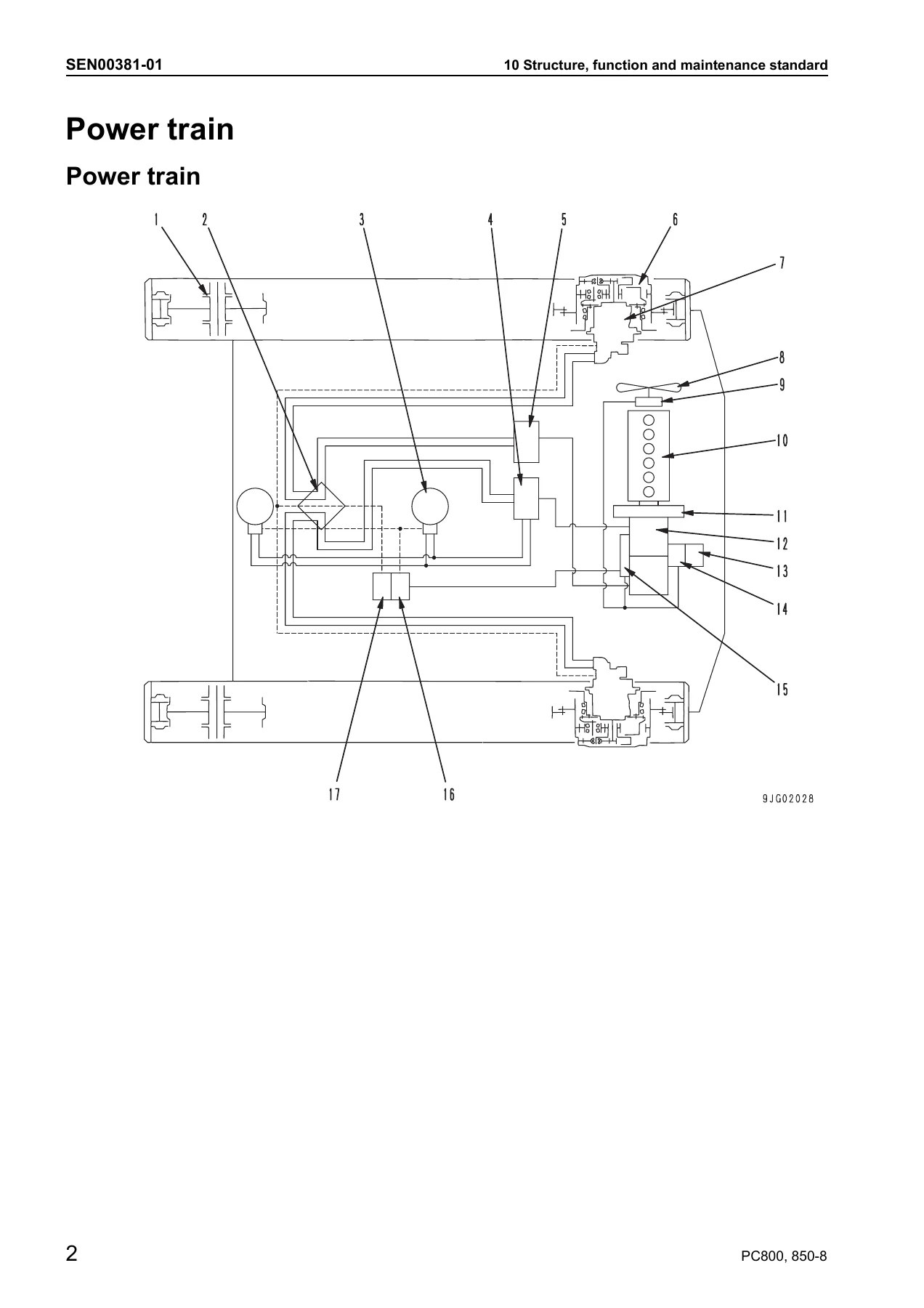
Power trainp. 89
Swing machineryp. 91
Swing circlep. 93
Final drivep. 95
Sprocketp. 97
+Undercarriage and framep. 100
+Undercarriage and framep. 101
Track frame and recoil springp. 101
Idlerp. 103
Carrier rollerp. 105
Track rollerp. 107
Track shoep. 109
Double shoep. 112
+Hydraulic system, Part 1p. 114
+Hydraulic system, Part 1p. 115
Hydraulic piping drawingp. 115
Hydraulic tank, hydraulic filterp. 117
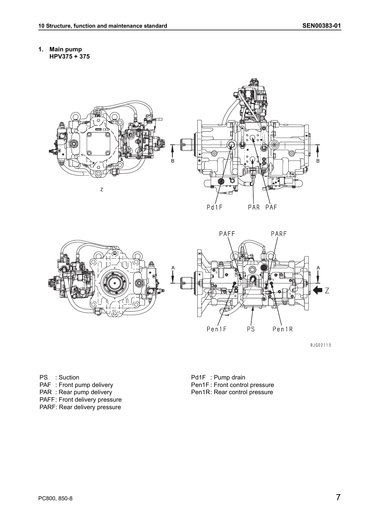
Hydraulic pumpp. 119
Operation of pump control mechanismp. 125
EPC valvep. 127
Self pressure reducing valvep. 130
Cooling fan pumpp. 134
Cooling fan motorp. 143
+Hydraulic system, Part 2p. 150
+Hydraulic system, Part 2p. 153
Motor grease pumpp. 153
Return oil filterp. 154
Line oil filterp. 155
Drain oil filterp. 156
L.H. 5-Spool control valvep. 157
R.H. 4-Spool control valvep. 163
Straight-travel valvep. 169
Swing motorp. 172
Center swivel jointp. 177
Travel motorp. 178
PPC accumulatorp. 188
Work equipment, swing PPC valvep. 189
Travel PPC valvep. 195
Solenoid valvep. 199
Hydraulic cylinderp. 205
+Work equipmentp. 212
+Work equipmentp. 213
Work equipmentp. 213
Dimensions of work equipmentp. 219
+Cab and its attachmentsp. 224
+Cab and its attachmentsp. 225
Air conditioner pipingp. 225
+Electrical systemp. 228
+Electrical systemp. 229
Engine controlp. 229
Electric control systemp. 238
Monitor systemp. 272
Sensorsp. 290
+20 Standard value tablep. 296
+Standard service value tablep. 296
Standard service value table for enginep. 297
Standard service value table for chassisp. 298
+30 Testing and adjustingp. 310
+Testing and adjusting, Part 1p. 310
+Testing and adjusting, Part 1p. 311
Tools for testing, adjusting and troubleshootingp. 311
Measuring engine speedp. 313
Measuring intake air pressure (Boost pressure)p. 314
Measuring exhaust gas temperaturep. 315
Measuring exhaust gas colorp. 316
Adjusting valve clearancep. 317
Measuring compression pressurep. 318
Measuring blow-by pressurep. 319
Measuring engine oil pressurep. 320
Handling of fuel system equipmentp. 321
Remaining pressure relief from fuel system equipmentp. 321
Measuring fuel pressurep. 322
Testing fuel return rate and leakagep. 323
Bleeding air from fuel circuitp. 325
Testing and adjusting alternator belt tensionp. 326
Testing and adjusting air conditioner compressor beltp. 327
+Testing and adjusting, Part 2p. 330
+Testing and adjusting, Part 2p. 331
Inspection of swing circle bearing clearancep. 331
Testing and adjusting track shoe tensionp. 332
Testing and adjusting work equipment, swing, and travel circuit oil pressuresp. 333
Testing and adjusting control circuit oil pressure (self pressure reducing valve)p. 338
Testing and adjusting main pump control pressurep. 339
+Testing and adjusting, Part 3p. 346
Testing and adjusting, Part 3p. 347
Measuring PPC valve output pressurep. 347
Measuring outlet pressures of solenoid valve, swing PPC shuttle valve, and swing priorit yselector valvep. 351
Adjusting work equipment, swing PPC valvep. 355
Testing and adjusting travel deviationp. 356
Inspection of locations of hydraulic drift of work equipmentp. 358
Measuring fan speedp. 359
Measuring fan circuit oil pressurep. 359
Measuring fan pump EPC currentp. 360
Measuring fan pump EPC solenoid valve output pressurep. 360
Measuring oil leakagep. 361
Release of residual pressure from hydraulic circuitp. 365
Bleeding air from each partp. 366
Inspection procedures for diodep. 369
+Testing and adjusting, Part 4p. 372
+Testing and adjusting, Part 4p. 373
Special function of machine monitorp. 373
Handling engine controller high voltage circuitp. 404
+Testing and adjusting, Part 5p. 406
+Testing and adjusting, Part 5p. 407
Procedure for turning on KOMTRAX terminalp. 407
KOMTRAX terminal lamp indicationsp. 410
Preparation work for troubleshooting electrical systemp. 413
Pm-clinic servicep. 416
+40 Troubleshootingp. 426
+General information on troubleshootingp. 426
General information on troubleshootingp. 427
Points to remember when troubleshootingp. 427
Sequence of events in troubleshootingp. 428
Checks before troubleshootingp. 429
Classification and troubleshooting stepsp. 430
Connection table for connector pin numbersp. 434
T-boxes and T-adapters tablep. 457
+Troubleshooting by failure code (Display of code), Part 1p. 462
+Troubleshooting by failure code (Display of code), Part 1p. 464
Failure codes tablep. 464
Information in troubleshooting tablep. 469
Failure code [A000N1] Eng. Hi Out of Stdp. 471
Failure code [AA10NX] Aircleaner Cloggingp. 473
Failure code [AB00KE] Charge Voltage Lowp. 475
Failure code [B@BAZG] Eng. Oil Press. Lowp. 477
Failure code [B@BAZK] Eng. Oil Level Lowp. 479
Failure code [B@BCNS] Eng. Water Overheatp. 481
Failure code [B@BCZK] Eng. Water Lvl Lowp. 483
Failure code [B@HANS] Hydr. Oil Overheatp. 485
Failure code [CA111] ECM Critical Internal Failurep. 487
Failure code [CA115] Eng Ne and Bkup Speed Sens Errorp. 489
Failure code [CA122] Chg Air Press Sensor High Errorp. 490
Failure code [CA123] Chg Air Press Sensor Low Errorp. 492
Failure code [CA131] Throttle Sensor High Errorp. 493
Failure code [CA132] Throttle Sensor Low Errorp. 495
Failure code [CA135] Eng Oil Press Sensor High Errorp. 496
Failure code [CA141] Eng Oil Press Sensor Low Errorp. 498
Failure code [CA144] Coolant Temp Sens High Errorp. 499
Failure code [CA145] Coolant Temp Sens Low Errorp. 501
Failure code [CA153] Chg Air Temp Sensor High Errorp. 502
Failure code [CA154] Chg Air Temp Sensor Low Errorp. 504
Failure code [CA187] Sens Supply 2 Volt Low Errorp. 504
Failure code [CA221] Ambient Press Sens High Errorp. 505
Failure code [CA222] Ambient Press Sens Low Errorp. 507
Failure code [CA227] Sens Supply 2 Volt High Errorp. 508
Failure code [CA234] Eng Overspeedp. 510
Failure code [CA238] Ne Speed Sens Supply Volt Errorp. 511
Failure code [CA263] Fuel Temp Sensor High Errorp. 513
Failure code [CA265] Fuel Temp Sensor Low Errorp. 515
Failure code [CA271] IMV/PCV1 Short Errorp. 516
Failure code [CA272] IMV/PCV1 Open Errorp. 517
Failure code [CA273] PCV2 Short Errorp. 518
Failure code [CA274] PCV2 Open Errorp. 519
Failure code [CA322] Inj #1 (L#1) Open/Short Errorp. 520
Failure code [CA323] Inj #5 (L#5) Open/Short Errorp. 521
Failure code [CA324] Inj #3 (L#3) Open/Short Errorp. 522
Failure code [CA325] Inj #6 (L#6) Open/Short Errorp. 523
Failure code [CA331] Inj #2 (L#2) Open/Short Errorp. 524
Failure code [CA332] Inj #4 (L#4) Open/Short Errorp. 525
Failure code [CA351] Injectors Drive Circuit Errorp. 527
Failure code [CA352] Sens Supply 1 Volt Low Errorp. 529
Failure code [CA386] Sens Supply 1 Volt High Errorp. 531
+Troubleshooting by failure code (Display of code), Part 2p. 534
+Troubleshooting by failure code (Display of code), Part 2p. 536
Failure code [CA441] Battery Voltage Low Errorp. 536
Failure code [CA442] Battery Voltage High Errorp. 536
Failure code [CA449] Rail Press Very High Errorp. 537
Failure code [CA451] Rail Press Sensor High Errorp. 539
Failure code [CA452] Rail Press Sensor Low Errorp. 541
Failure code [CA553] Rail Press High Errorp. 541
Failure code [CA554] Rail Press Sensor In Range Errorp. 542
Failure code [CA559] Rail Press Low Errorp. 543
Failure code [CA689] Eng Ne Speed Sensor Errorp. 547
Failure code [CA731] Eng Bkup Speed Sens Phase Errorp. 549
Failure code [CA757] All Persistent Data Lost Errorp. 550
Failure code [CA778] Eng Bkup Speed Sensor Errorp. 551
Failure code [CA1228] EGR Valve Servo Error 1p. 553
Failure code [CA1625] EGR Valve Servo Error 2p. 554
Failure code [CA1626] BP Valve Sol Current High Errorp. 555
Failure code [CA1627] BP Valve Sol Current Low Errorp. 557
Failure code [CA1628] Bypass Valve Servo Error 1p. 558
Failure code [CA1629] Bypass Valve Servo Error 2p. 559
Failure code [CA1631] BP Valve Pos Sens High Errorp. 561
Failure code [CA1632] BP Valve Pos Sens Low Errorp. 563
Failure code [CA1633] KOMNET Datalink Timeout Errorp. 564
Failure code [CA1642] EGR Inter Press Sens Low Errorp. 566
Failure code [CA2185] Throt Sens Sup Volt High Errorp. 569
Failure code [CA2186] Throt Sens Sup Volt Low Errorp. 571
Failure code [CA2249] Rail Press Very Low Errorp. 572
Failure code [CA2271] EGR Valve Pos Sens High Errorp. 573
Failure code [CA2272] EGR Valve Pos Sens Low Errorp. 575
Failure code [CA2351] EGR Valve Sol Current High Errorp. 577
Failure code [CA2352] EGR Valve Sol Current Low Errorp. 579
Failure code [CA2555] Grid Htr Relay Volt Low Errorp. 580
Failure code [CA2556] Grid Htr Relay Volt High Errorp. 581
Failure code [D110KB] Battery Relay Drive S/Cp. 583
Failure code [D163KB] Flash Light Relay S/Cp. 585
Failure code [D195KB] Step Light Relay S/Cp. 587
Failure code [DA25KP] Press. Sensor Power Abnormalityp. 589
Failure code [DA2SKQ] Model Selection Abnormalityp. 591
Failure code [DA80MA] Auto. Lub. Abnormalp. 593
Failure code [DA2RMC] Pump Comm. Abnormalityp. 595
Failure code [DAFRMC] Monitor Comm. Abnormalityp. 597
Failure code [DGE5KY] Ambi. Temp. Sensor S/Cp. 599
Failure code [DGH2KB] Hydr. Oil Temp. Sensor S/Cp. 601
+Troubleshooting by failure code (Display of code), Part 3p. 604
+Troubleshooting by failure code (Display of code), Part 3p. 607
Failure code [DH25KA] L Jet Sensor Discp. 607
Failure code [DH25KB] L Jet Sensor S/Cp. 609
Failure code [DH26KA] R Jet Sensor Disc.p. 611
Failure code [DH26KB] R Jet Sensor S/Cp. 613
Failure code [DHPEKA] F Pump P. Sensor Disc.p. 615
Failure code [DHPEKB] F Pump P. Sensor S/Cp. 617
Failure code [DHPFKA] R Pump P. Sensor Disc.p. 619
Failure code [DHPFKB] R Pump P. Sensor S/Cp. 621
Failure code [DV20KB] Travel Alarm S/Cp. 623
Failure code [DW41KA] Swing Priority Sol. Disc.p. 625
Failure code [DW41KB] Swing Priority Sol. S/Cp. 627
Failure code [DW43KA] Travel Speed Sol. Disc.p. 629
Failure code [DW43KB] Travel Speed Sol. S/Cp. 631
Failure code [DW45KA] Swing Brake Sol. Disc.p. 633
Failure code [DW45KB] Swing Brake Sol. S/Cp. 635
Failure code [DW7BKA] Fan Reverse Sol. Disc.p. 637
Failure code [DW78KB] Fan Reverse Sol. S/Cp. 639
Failure code [DWK0KA] 2-stage Relief Sol. Disc.p. 641
Failure code [DWK0KB] 2-stage Relief Sol. S/Cp. 643
Failure code [DX16KA] Fan Pump EPC Sol. Disc.p. 645
Failure code [DX16KB] Fan Pump EPC Sol. S/Cp. 647
Failure code [DXAAKA] F Pump EPC Sol. Disc.p. 649
Failure code [DXAAKB] F Pump EPC Sol. S/Cp. 651
Failure code [DXABKA] R Pump EPC Sol. Disc.p. 653
Failure code [DXABKB] R Pump EPC Sol. S/Cp. 655
Failure code [DY20KA] Wiper Working Abnormalityp. 657
Failure code [DY20MA] Wiper Parking Abnormalityp. 659
Failure code [DY2CKB] Washer Drive S/Cp. 663
Failure code [DY2DKB] Wiper Drive (For) S/Cp. 665
Failure code [DY2EKB] Wiper Drive (Rev) S/Cp. 669
+Troubleshooting of electrical system (E-mode)p. 672
+Troubleshooting of electrical system (E-mode)p. 674
Before carrying out troubleshooting of electrical systemp. 674
Information contained in troubleshooting tablep. 676
E-1 Engine does not start (Engine does not rotate)p. 677
E-2 Preheater does not operatep. 680
E-3 Auto engine warm-up device does not workp. 685
E-4 Auto-decelerator does not operatep. 686
E-5 All work equipment, swing and travel do not movep. 687
E-6 Machine push-up function does not operate normallyp. 689
E-7 Boom shockless function does not operate normallyp. 691
E-8 Any item is not displayed on machine monitorp. 693
E-9 Part of display on machine monitor is missingp. 694
E-10 Machine monitor displays contents irrelevant to the modelp. 694
E-11 Fuel level monitor red lamp lights up while engine is runningp. 695
E-12 Engine coolant thermometer does not display normallyp. 697
E-13 Hydraulic oil temperature gauge does not display correctlyp. 699
E-14 Fuel gauge does not display correctlyp. 700
E-15 Swing lock monitor does not display correctlyp. 701
E-16 When monitor switch is operated, nothing is displayedp. 703
E-17 Windshield wiper and window washer do not workp. 705
E-18 "Boom RAISE" is not correctly displayed in monitor functionp. 713
E-19 "Boom LOWER" is not correctly displayed in monitor functionp. 714
E-20 "Arm IN" is not correctly displayed in monitor functionp. 715
E-21 "Arm OUT" is not correctly displayed in monitor functionp. 716
E-22 "Bucket CURL" is not correctly displayed in monitor functionp. 717
E-23 "Bucket DUMP" is not correctly displayed in monitor functionp. 718
E-24 "SWING" is not correctly displayed in monitor functionp. 719
E-25 "Left travel" is not displayed normally in monitoring functionp. 721
E-26 "Right travel" is not displayed normally in monitoring functionp. 723
E-27 "Service" is not correctly displayed in monitor functionp. 725
E-28 KOMTRAX system does not operate normallyp. 727
E-29 Air conditioner does not workp. 729
E-30 Step light does not light up or go offp. 730
E-31 Electric grease gun does not operatep. 733
E-32 Travel alarm does not sound or does not stop soundingp. 735
+Troubleshooting of hydraulic and mechanical system (H-mode)p. 738
+Troubleshooting of hydraulic and mechanical system (H-mode)p. 740
Information in troubleshooting tablep. 740
H-1 Speed or power of all work equipment, travel, and swing is lowp. 741
H-2 Engine speed lowers remarkably or engine stallsp. 743
H-3 All work equipment, travel, and swing systems do not workp. 744
H-4 Abnormal sound is heard from around pumpp. 745
H-5 Boom speed or power is lowp. 746
H-6 Speed or power of arm is lowp. 748
H-7 Speed or power of bucket is lowp. 749
H-8 Boom does not movep. 750
H-9 Arm does not movep. 750
H-10 Bucket does not movep. 750
H-11 Hydraulic drift of work equipment is largep. 751
H-12 Time lag of work equipment is largep. 753
H-13 Heavy lift function does not operate or stopp. 754
H-14 Machine push-up function does not operate or stopp. 754
H-15 Boom shockless function cannot be turned ON or OFFp. 754
H-16 Machine deviates in one directionp. 755
H-17 Machine deviates largely at startp. 757
H-18 Machine deviates largely during compound operationp. 758
H-19 Travel speed or power is lowp. 758
H-20 Machine does not travel (only one track)p. 759
H-21 Travel speed does not changep. 760
H-22 Upper structure does not swingp. 761
H-23 Swing speed or acceleration is lowp. 763
H-24 Swing speed or acceleration is low during compound operation of swing and work equipmentp. 764
H-25 Upper structure overruns excessively when it stops swingingp. 766
H-26 Large shock is made when upper structure stops swingingp. 767
H-27 Large abnormal sound is made when upper structure stops swingingp. 768
H-28 Hydraulic drift of swing is largep. 769
+Troubleshooting of engine (S-mode)p. 772
+Troubleshooting of engine (S-mode)p. 774
Method of using troubleshooting chartp. 774
S-1 Starting performance is poorp. 777
S-2 Engine does not startp. 779
S-3 Engine does not pick up smoothlyp. 783
S-4 Engine stops during operationsp. 784
S-6 Engine lacks output (or lacks power)p. 786
S-7 Exhaust gas color is black (incomplete combustion)p. 787
S-8 Oil consumption is excessive (or exhaust smoke is blue)p. 789
S-9 Oil becomes contaminated quicklyp. 790
S-10 Fuel consumption is excessivep. 791
S-11 Oil is in coolant (or coolant spurts back or coolant level goes down)p. 792
S-12 Oil pressure dropsp. 793
S-13 Oil level rises (Entry of coolant/fuel)p. 794
S-14 Coolant temperature becomes too high (overheating)p. 796
S-15 Abnormal noise is madep. 797
S-16 Vibration is excessivep. 798
+50 Disassembly and assemblyp. 800
+General information on disassembly and assemblyp. 800
+General information on disassembly and assemblyp. 801
How to read this manualp. 801
Coating materials listp. 803
Special tools listp. 806
Sketches of special toolsp. 813
+Engine and cooling system, Part 1p. 818
+Engine and cooling system, Part 1p. 819
Removal and installation of engine, PTO and hydraulic pump assemblyp. 819
Removal and installation of cooling assemblyp. 827
Removal and installation of aftercoolerp. 832
Removal and installation of fuel cooler and air conditioner condenser assemblyp. 834
Removal and installation of fan motor assemblyp. 836
Removal and installation of fuel tank assemblyp. 841
+Engine and cooling system, Part 2p. 844
+Engine and cooling system, Part 2p. 845
Removal and installation of fuel supply pump assemblyp. 845
Removal and installation of cylinder head assemblyp. 850
Removal and installation of fuel injector assemblyp. 866
Removal and installation of engine front sealp. 869
Removal and installation of engine rear sealp. 871
+Power trainp. 876
Power trainp. 877
Removal and installation of PTO (coupling) assemblyp. 877
Disassembly and assembly of PTO (coupling) assemblyp. 881
Removal and installation of swing motor and swing machinery assemblyp. 883
Disassembly and assembly of swing machinery assemblyp. 885
Removal and installation of swing circle assemblyp. 892
Disassembly and assembly of final drive assemblyp. 893
+Undercarriage and framep. 904
Undercarriage and framep. 905
Removal and installation of trac kshoe assemblyp. 905
Disassembly and assembly of one link in fieldp. 907
Removal and installation of idler assemblyp. 911
Disassembly and assembly of idler assemblyp. 912
Disassembly and assembly of idler adjustment cylinder assemblyp. 915
Removal and installation of recoil spring assemblyp. 916
Disassembly and assembly of recoil spring assemblyp. 918
Removal and installation of carrier roller assemblyp. 920
Disassembly and assembly of carrier roller assemblyp. 921
Removal and installation of track roller assemblyp. 923
Disassembly and assembly of track roller assemblyp. 924
Removal and installation of revolving frame assemblyp. 927
Removal and installation of counterweight assemblyp. 929
+Hydraulic systemp. 932
Hydraulic systemp. 933
Removal and installation of hydraulic tank assemblyp. 933
Removal and installation of main pump assemblyp. 936
Removal and installation of main pump input shaft oil sealp. 941
Removal and installation of cooling fan pump assemblyp. 942
Removal and installation of control valve assemblyp. 945
Assembly of control valve assemblyp. 948
Removal and installation of swing motor assemblyp. 952
Removal and installation of center swivel jointp. 954
Disassembly and assembly of center swivel joint assemblyp. 956
Removal and installation of travel motor assemblyp. 958
Removal and installation of solenoid valve assemblyp. 959
Removal and installation of boom damping valve assemblyp. 961
Disassembly and assembly of work equipment PPC valve assemblyp. 962
Disassembly and assembly of travel PPC valve assemblyp. 964
Disassembly and assembly of hydraulic cylinder assemblyp. 965
+Work equipmentp. 972
+Work equipmentp. 973
Removal and installation of bucket cylinder assemblyp. 973
Removal and installation of arm cylinder assemblyp. 977
Removal and installation of boom cylinder assemblyp. 981
Removal and installation of bucket assemblyp. 986
Removal and installation of arm assemblyp. 988
Removal and installation of boom assemblyp. 991
Removal and installation of work equipmentp. 995
+Cab and its attachmentsp. 1000
+Cab and its attachmentsp. 1001
Removal and installation of operatorβs cabp. 1001
Removal and installation of operatorβs cab glass (stuck glass)p. 1004
Removal and installation of front window assemblyp. 1014
+Electrical systemp. 1020
Electrical systemp. 1021
Removal and installation of air conditioner unit assemblyp. 1021
Removal and installation of engine controller assemblyp. 1023
Removal and installation of monitor assemblyp. 1025
Removal and installation of pump controllerp. 1025
Removal and Installation of KOMTRAX terminal assemblyp. 1026
+90 Diagrams and drawingsp. 1028
+Hydraulic diagrams and drawingsp. 1028
+Hydraulic diagrams and drawingsp. 1030
Hydraulic circuit diagramp. 1030
+Electrical diagrams and drawingsp. 1033
Electrical circuit diagram (1/5)p. 1035
Electrical circuit diagram (2/5)p. 1036
Electrical circuit diagram (3/5)p. 1037
Electrical circuit diagram (4/5)p. 1038
Electrical circuit diagram (5/5)p. 1039
This is a digital PDF download β no physical shipment, no waiting. After payment the file is available immediately, and you can open it on any laptop, tablet, or phone in the workshop, or print the pages you need for the job at hand. Having the correct procedures and the exact specifications in front of you is what separates a repair that lasts from one that comes back. Get the manual, get the numbers, and get the machine back to work.
Reviews
There are no reviews yet.