
Komatsu PC490LC-11 Shop Manual SEN06738-08 – Complete PDF Service, Repair & Troubleshooting Guide
Original price was: $84.95.$52.95Current price is: $52.95.
The complete Komatsu PC490LC-11 Shop Manual, document SEN06738-08, covering serial numbers 85001 and up. Over 2,200 pages covering engine, urea SCR, hydraulic, electrical, undercarriage and cab systems. Instant PDF download.
Description
Komatsu PC490LC-11 Shop Manual SEN06738-08 – Full Service, Repair & Troubleshooting Reference
This is the complete Komatsu PC490LC-11 Shop Manual, document number SEN06738-08, covering the hydraulic excavator from serial number 85001 and up. At more than 2,200 pages, it is the full service reference for this machine — not a condensed guide, not a selection of chapters. Engine, urea SCR aftertreatment, CLSS hydraulics, swing and travel circuits, undercarriage, cab assembly and the complete electrical system are all documented to the level a working technician needs. Whether you are diagnosing a failure code, setting relief pressures, pulling a final drive, or writing an injector compensation value, the procedure and the numbers are here.
File Details
- Manual Type: Shop Manual
- Brand: Komatsu
- Model: PC490LC-11
- Document Number: SEN06738-08
- Language: English
- Page Count: 2,225
- File Format: PDF
- Serial Number Coverage: 85001 and up, with dedicated sections for 85001 to 86052, 86053 to 86205, 86206 and up, 85001 to 86281, and 86282 and up
Chapters Covered
- 00 Index and Foreword
- 01 Specifications
- 10 Structure and Function
- 20 Standard Value Table
- 30 Testing and Adjusting
- 40 Troubleshooting
- 50 Disassembly and Assembly
- 60 Maintenance Standard
- 80 Appendix
- 90 Circuit Diagrams
00 Index and Foreword
Safety notices for operation and maintenance, fire prevention, first-response actions if a fire occurs, waste material disposal, DEF handling and storage precautions, and the engine technology used to meet Tier 4 Final and Stage IV exhaust gas emission regulations. The abbreviation list covers the terms used throughout the manual. Standard tightening torque tables for metric and unified threads, O-ring boss piping joints, O-ring boss plugs, hose fittings, face seal joints and engine-specific bolts are all included. Conversion tables for length, mass, volume, pressure and temperature are provided. The connector section explains how to disconnect and connect push-pull type couplers, Deutsch connectors, slide lock connectors, connectors with lock to pull or push, and connectors with housing to rotate. The hydraulic and electrical handling precautions are here, as is how to read the electric cable codes.
01 Specifications
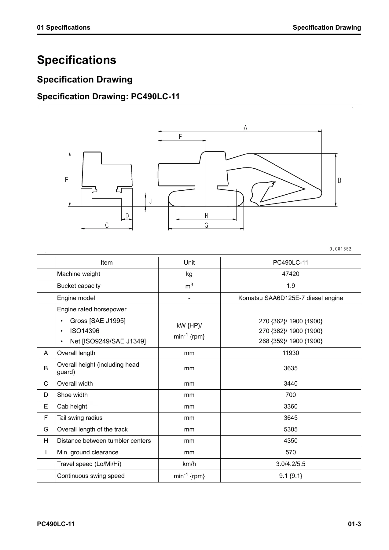
Specification drawings and working range drawings for the PC490LC-11, with the overall dimensions and the digging envelope. The specifications tables give the machine weight, bucket capacity, SAA6D125E-7 engine model and rated horsepower, travel speeds, swing speed, ground pressure, and undercarriage details. The weight table itemises every major component assembly — engine, main pump, radiator and oil cooler, hydraulic tank, fuel tank, operator cab, counterweight, swing machinery, control valve, swing motor, travel motors, track frame, track shoes, boom, arm, bucket, and each cylinder. The fuel, coolant, and lubricants table covers capacities and recommended fluids for the engine oil pan, swing machinery case, final drive case, damper case, hydraulic system, cooling system, fuel tank, and DEF tank.
10 Structure and Function
This is the theory chapter — how each system works before you troubleshoot it. The urea SCR system is covered in detail, including the DEF tank, DEF tank sensor, DEF pump, DEF injector, DEF hose, DEF tank heating valve, and the SCR assembly with its ammonia sensor, NOx sensors and temperature sensors. The engine system chapter covers the VGT, EGR system and EGR valve, EGR cooler, KCCV system and ventilator, and KDPF. The cooling system chapter explains the fan speed control system, the engine output control system, and the fan reverse rotation system. The control system chapter covers the machine monitor, KomVision controller and camera, and the KOMTRAX system. The hydraulic system chapter explains CLSS, the unload valve operation, pump swash plate angle control, pressure compensation control, LS bypass plug, LS select valve, and the engine and pump combined control system. The work equipment, swing, and travel systems each have their own structure and function sections. The undercarriage, work equipment, and cab-related parts close out the chapter.
20 Standard Value Table
The standard values and repair limits for the engine and the machine. Engine values include high idle speed, low idle speed, rated speed, boost pressure, exhaust temperature, exhaust gas colour limits, valve clearance, EGR and VGT oil pressures, compression pressure, blowby pressure, fuel pressure, fuel return rates, engine oil pressure, and engine oil temperature. Machine values cover engine speed at two-pump relief and with one-touch power maximizing, auto-deceleration speed, control valve spool strokes, control lever travels and operating forces, work equipment, swing, and travel relief pressures, control circuit source pressure, PC and LS valve output pressures, LS differential pressure, swing overswing and timing, travel speeds and deviation, hydraulic drift limits, work equipment speeds, time lags, oil leakage volumes, cooling fan speed and circuit pressure, fan pump EPC current, and pump performance values. The machine posture and measurement procedures section shows how to set the machine up for each of these tests.
30 Testing and Adjusting
How to test and adjust the machine. The engine and cooling system section covers engine speed, boost pressure, exhaust gas colour, mass air flow and temperature sensor, valve clearance, compression pressure, blowby pressure, engine oil pressure, EGR valve and VGT oil pressure, fuel pressure, fuel return rate and leakage, bleeding the fuel system, fuel circuit leakage, cylinder cut-out mode, no-injection cranking, air conditioner compressor belt tension, fuel doser cleaning, injector compensation value writing, and soot accumulation correction. The power train section covers swing circle bearing clearance. The undercarriage section covers track tension. The hydraulic system section covers releasing remaining pressure, work equipment, swing, and travel circuit pressures, control circuit pressure, PC and LS control circuit pressures, solenoid valve outlet pressure, PPC valve outlet pressure, PPC valve play, pump swash plate sensor, cooling fan speed, fan pump circuit pressure, fan pump EPC current, fan pump EPC solenoid valve outlet pressure, hydraulic drift causes, oil leakage, bleeding the hydraulic circuit, and accumulator nitrogen gas pressure. The cab section covers the tipping stopper and mirrors. The electrical section covers the machine monitor, KOMTRAX startup, rearview camera angle, KomVision camera angle and related functions, Bluetooth radio region setting, engine controller voltage circuit, battery disconnect switch, diodes, and Pm Clinic.
40 Troubleshooting
The largest chapter. It contains the failure code table, then a full troubleshooting entry for each failure code — 879AKA, 879AKB, 879BKA, 879BKB, 879CKA, 879CKB, 879DKZ, 879EMC, 879FMC, 879GKX, 989L00, 989M00, 989N00, A1U0N3, A1U0N4, A900FR, A900N6, A900NY, AA10NX, AB00KE, AQ10N3, AS00N3, AS00R2 through AS00R6, AS00ZK, AS10KM, AS10NR, AS10NT, B@BAZG, B@BAZK, B@BCNS, B@BCQA, B@BCZK, B@HANS, CA115 through CA5383, D110KB, D19JKZ, D811MC, D862KA, D8ALKA, D8ALKB, D8AQKR, D8G1KT, D8G6KT, DA20MC, DA22KK, DA25KP, DA29KQ, DA2LKA, DA2LKB, DA2QKR, DA2RKR, DAF0MB, DAF0MC, DAF8KB, DAF9KQ, DAFGMC, DAFLKA, DAFLKB, DAFQKR, DAZ9KQ, DAZQKR, DB2QKR, DB2RKR, DBP0KM, DBP0KT, DBP5KB, DBP5KY, DBPQKR, DDNRKA, DDNRKY, DDNS00, DGH2KA, DGH2KB, DHA4KA, DHAAMA, DHACMA, DHPAMA, DHPBMA, DHS3MA, DHS4MA, DHS8MA, DHS9MA, DHSAMA, DHSBMA, DHSCMA, DHSDMA, DHSFMA, DHSGMA, DHSHMA, DHSJMA, DHSVMA, DHZAMA, DHZCL8, DKR0MA, DKR1MA, DKULKA, DKULKB, DKULKY, DLM3KA, DLM3KB, DLM3MB, DR10KA, DR12KA, DR20KA, DR21KX, DR30KA, DR31KX, DR40KA, DUMBKA, DUMBKB, DV20KB, DW43KA, DW43KB, DW43KY, DW45KA, DW45KB, DW45KY, DW4CKY, DW7BKA, DW7BKB, DW7BKY, DW91KA, DW91KB, DW91KY, DWA2KA, DWA2KB, DWA2KY, DWK0KA, DWK0KB, DWK0KY, DWK2KA, DWK2KB, DWK2KY, DWK8KA, DWK8KB, DWK8KY, DWPUKA, DWPUKB, DWPUKY, DX16KA, DX16KB, DXA8KA, DXA8KB, DXA9KA, DXA9KB, DXE0KA, DXE0KB, DXE4KA, DXE4KB, DXE4KY, DXE5KA, DXE5KB, DXE6KA, DXE6KB, DXE7KA, DXE7KB, DXE7KY, DXE8KA, DXE8KB, DXE8KY, DXE9KA, DXE9KB, DXE9KY, DXEAKA, DXEAKB, DXEAKY, DXEKKA, DXEKKB, DXEKKY, DXELKA, DXELKB, DXELKY, DY20KA, DY20MA, DY2CKB, DY2DKB, DY2EKB, F311KA, F311KB, F312KA, F312KB, F313KA, F313KB, F314KA, F314KB, F315KB, F315KY, F316KB, F316KY, F318KB, F318KY, F31AKB, F31AKY, F31BKB, F31BKY, F31CKB, F31CKY, F31DKB, F31DKY, F31EKB, and F31EKY. The E-mode section covers electrical system troubleshooting by symptom — engine does not start, preheating systems, machine monitor display, oil and coolant level monitors, temperature monitors, fuel gauge, hydraulic oil temperature gauge, function switches, auto-deceleration, working mode, travel speed, alarm buzzer, service meter, service mode, work equipment swing and travel, swing brake, one-touch power maximizing, travel alarm, horn, wiper and washer, monitoring function displays, attachment hydraulic circuit, KOMTRAX, and machine push-up. The H-mode section covers hydraulic and mechanical system troubleshooting by symptom — all work equipment swing and travel, speed and power, fine control, unusual noise, engine speed drop, boom arm and bucket speed and power, hydraulic drift, time lag, one-touch power maximizing, machine push-up, attachment circuit and oil flow, combined operations, travel, steering, swing, fan speed, and fan noise. The S-mode section covers engine troubleshooting by symptom — cranking, exhaust smoke, misfiring, startability, pick-up, stopping, rough running, power, KDPF clogging, oil consumption, oil contamination, fuel consumption, oil in coolant, oil pressure, fuel in oil, water in oil, overheating, unusual noise, vibration, air bleeding, active regeneration frequency and duration, white smoke, DEF consumption, unusual smell, and foreign materials in DEF.
50 Disassembly and Assembly
Component removal, installation, disassembly, and assembly procedures, with the special tools, tightening torques, coating materials, and weights shown for each job. Engine and cooling system procedures cover the supply pump, injector, fuel doser, cylinder head, EGR valve, EGR cooler, starting motor, alternator belt, radiator, cooling fan and fan motor, hydraulic oil cooler, aftercooler, engine and main pump assembly, engine front and rear oil seals, engine hood, fuel tank, DEF tank, DEF tank sensor flange, DEF tank sensor, DEF tank filler port filter, KDPF, SCR assembly, KDPF and SCR assembly, bellows pipe, KCCV, DEF mixing tube, DEF injector, DEF pump, DEF hose, air cleaner, and air conditioner compressor and condenser. Power train procedures cover the travel motor and final drive, final drive disassembly and assembly, swing motor and swing machinery, swing machinery disassembly and assembly, and swing circle. Undercarriage and frame procedures cover track separation and connection, sprocket, idler and idler cushion, idler disassembly and assembly, idler cushion disassembly and assembly, track roller, carrier roller, revolving frame, and counterweight. Hydraulic system procedures cover the center swivel joint, hydraulic tank, main pump, control valve, ATT bypass solenoid, work equipment PPC valve, and travel PPC valve. Work equipment procedures cover the work equipment assembly, boom anti-drop valve, arm anti-drop valve, anti-drop valve disassembly and assembly, and work equipment cylinder. Cab procedures cover the operator cab, cab glass, front window, floor frame, air conditioner unit, operator seat, seat belt, work equipment control lever, and front wiper. Electrical system procedures cover the engine controller, pump controller, machine monitor, KomVision controller, pump swash plate sensor, mass air flow and temperature sensor, KCCV crankcase pressure sensor, SCR temperature sensor, KomVision camera, gateway function controller, communication terminal wiring harness, and communication terminal.
60 Maintenance Standard
The maintenance standard values for each component — the criteria used to judge whether a part can be reused or must be replaced or repaired. It covers engine mounts, cooling system, cooling fan pump and motor, swing circle, swing machinery, final drive, sprocket and sprocket tooth profile, track frame and idler cushion, idler, track roller, carrier roller, track shoes and triple shoes, main pump, swing motor, travel motor, control valve, boom anti-drop valve, arm anti-drop valve, work equipment and swing PPC valve, travel PPC valve, 1st-line attachment PPC valve with EPC valve, solenoid valve, attachment circuit selector valve, center swivel joint, work equipment linkage, boom cylinder, arm cylinder, and bucket cylinder.
80 Appendix
The air conditioner system. It covers refrigerant precautions, air conditioner components and specifications, the refrigeration cycle structure and function, the air conditioner unit and its component parts, the air conditioner controller, compressor, condenser, receiver drier, and related sensors. The testing and troubleshooting section includes self-diagnosis, vent mode changeover, fresh/recirculation air changeover, sunlight sensor, refrigerant pressure switch, relay checks, troubleshooting charts, failure codes 879AKA through 879GKK, troubleshooting for the power supply system, compressor and refrigerant system, blower motor system, and fresh/recirc air changeover, troubleshooting by gauge pressure, service tool connection, and compressor oil handling.
90 Circuit Diagrams
The hydraulic circuit diagram and electrical circuit diagram. The hydraulic diagram shows the full circuit with the symbols used. The electrical circuit diagram is split into 11 sheets for machines 85001 to 86281 and another 11 sheets for machines 86282 and up, with a symbols key. These are the fold-out style diagrams you would normally find in the back of the printed manual.
Why This Manual Matters for PC490LC-11 Owners and Technicians
The PC490LC-11 is a Tier 4 Final machine with a urea SCR system, a VGT, an EGR cooler, and a KDPF — systems that did not exist on older Komatsu excavators. A generic diesel mechanic’s guide will not help you when the machine logs a DEF quality error or when the KDPF differential pressure sensor reads out of range. This manual tells you what the failure code means, what the controller is doing when it sets that code, and exactly which pins to measure, which connector to check, and which value is normal. The testing and adjusting chapter gives you the pressures, the differentials, the current draws, and the time lags, so you can prove a repair instead of guessing at it.
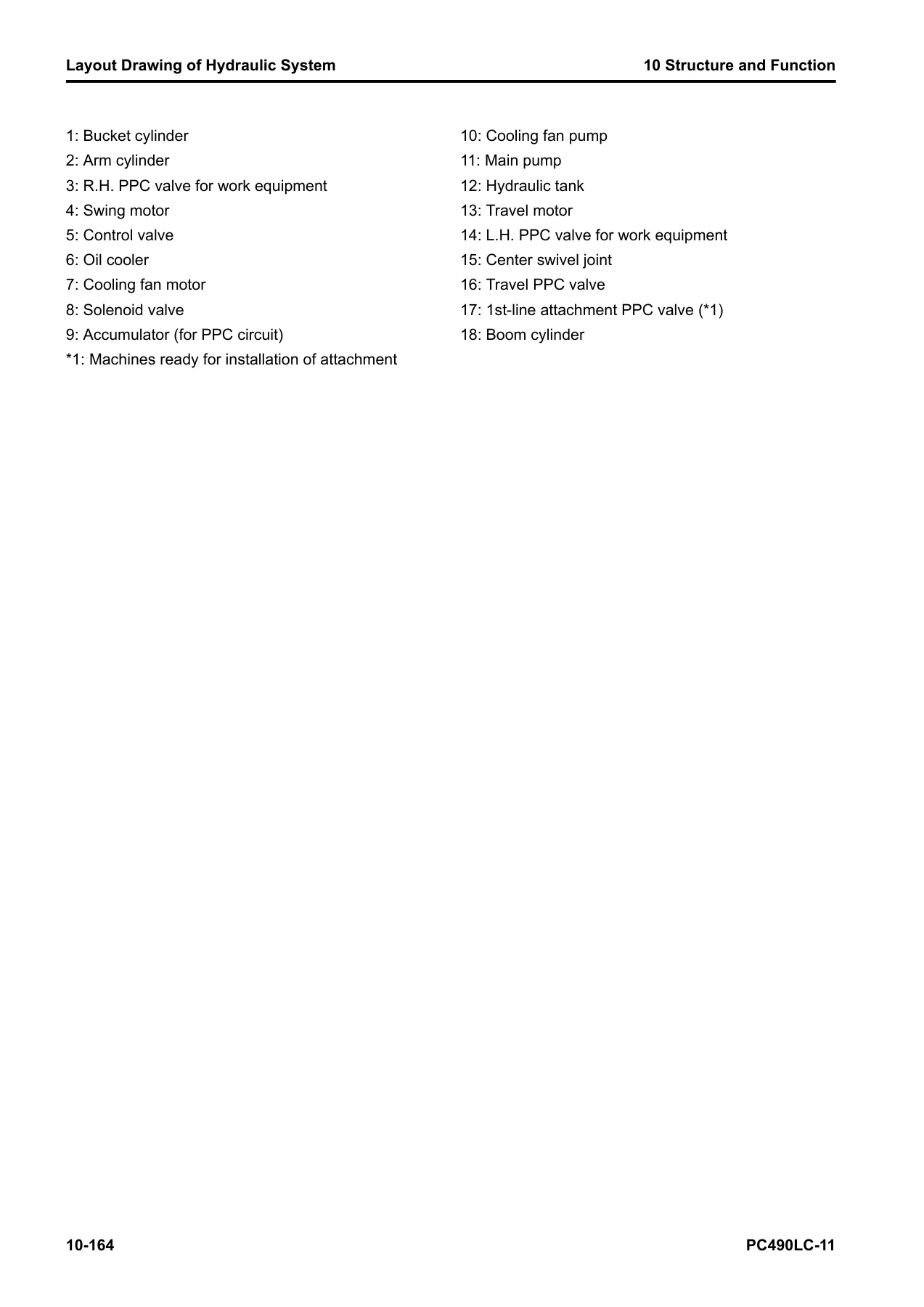
For the hydraulic system, this manual explains CLSS at the component level — the PC valve, the LS valve, the LS-EPC valve, the PC-EPC valve, the pressure compensation valves, the merge-divider, the travel junction, and the unload valve. When the machine lacks speed or power, the troubleshooting charts narrow the cause to a specific valve, a specific solenoid, or a specific sensor, and the standard value table gives you the number to compare against. For the engine and aftertreatment, the manual covers everything from the supply pump and injectors to the DEF pump, DEF injector, SCR assembly, and KDPF, including the regeneration procedures and the conditions that trigger them.
IMAGES PREVIEW
Instant PDF Delivery — No Shipping, No Waiting
This is a digital PDF. After payment, you download it immediately. It opens on any device — laptop, tablet, or phone — and you can print any page or any section you need in the workshop. No shipping cost, no delivery delay, no physical book to keep track of. The 2,225-page file is indexed and organised by chapter, so you can jump straight to the system you are working on. If you maintain, repair, or operate a PC490LC-11, this is the reference that covers the whole machine.
Reviews
There are no reviews yet.