
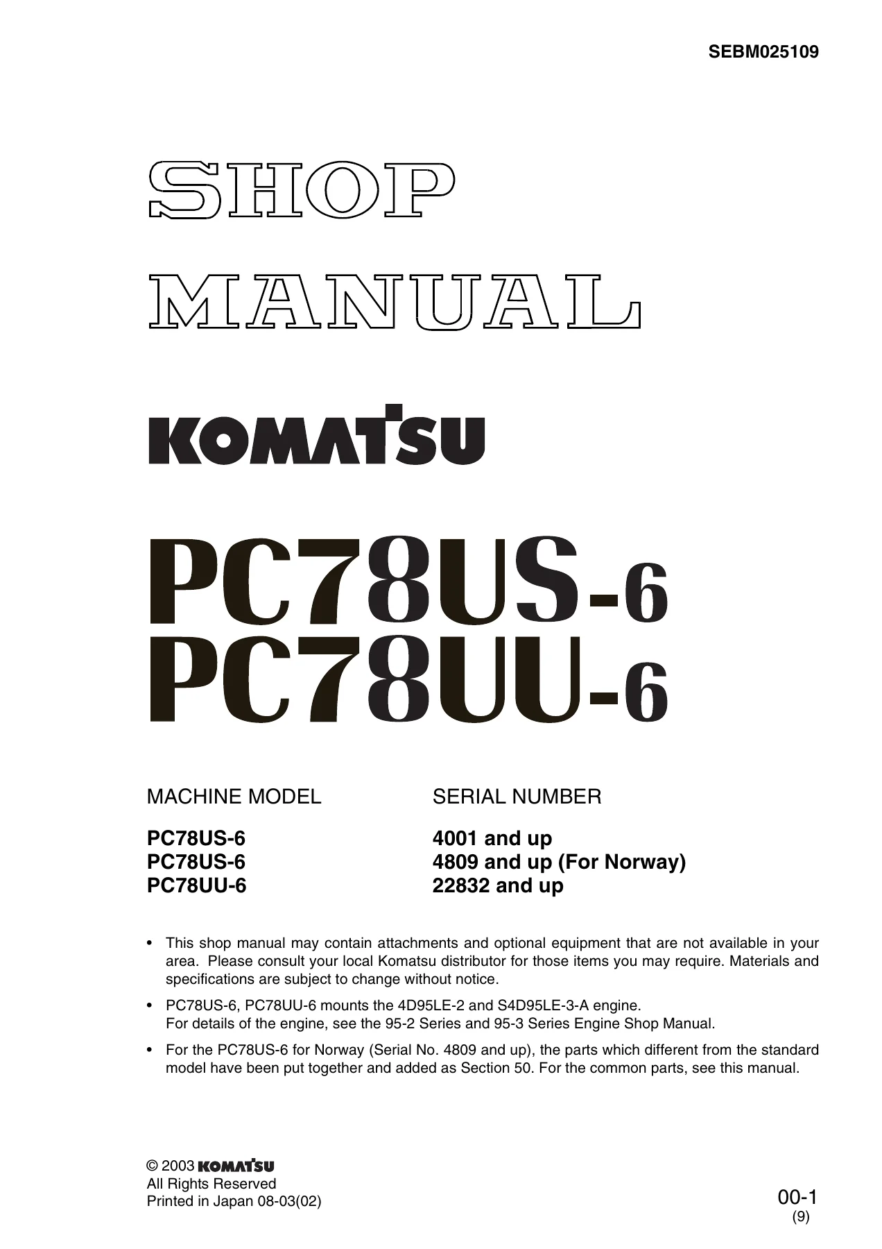
Komatsu PC78US-6 PC78UU-6 Excavator Shop Manual – SEBM025109 PDF Download
Original price was: $39.95.$24.95Current price is: $24.95.
Complete Komatsu PC78US-6 and PC78UU-6 shop manual (SEBM025109). 785-page service workshop manual covering engine, hydraulics, swing, travel, work equipment, electrical system, troubleshooting, and circuit diagrams. Instant PDF download.
Description
Komatsu PC78US-6 and PC78UU-6 Excavator Shop Manual — SEBM025109
This Komatsu PC78US-6 PC78UU-6 Shop Manual (document number SEBM025109) is the complete service workshop manual for the Komatsu PC78US-6 and PC78UU-6 hydraulic excavators. It covers serial number PC78US-6 4001 and up, PC78US-6 4809 and up (For Norway), and PC78UU-6 22832 and up. The manual applies to machines equipped with the Komatsu 4D95LE-2 and S4D95LE-3-A diesel engines.
File Details
- Manual Type: Shop Manual (Service Workshop Manual)
- Brand: Komatsu
- Models: PC78US-6, PC78UU-6
- Document Number: SEBM025109
- Engines: 4D95LE-2, S4D95LE-3-A
- Serial Numbers: PC78US-6 4001 and up; PC78US-6 4809 and up (For Norway); PC78UU-6 22832 and up
- Language: English
- Page Count: 785
- File Format: PDF
Chapters Covered
The manual is divided into six major sections:
- 01 General
- Specification dimensions drawing
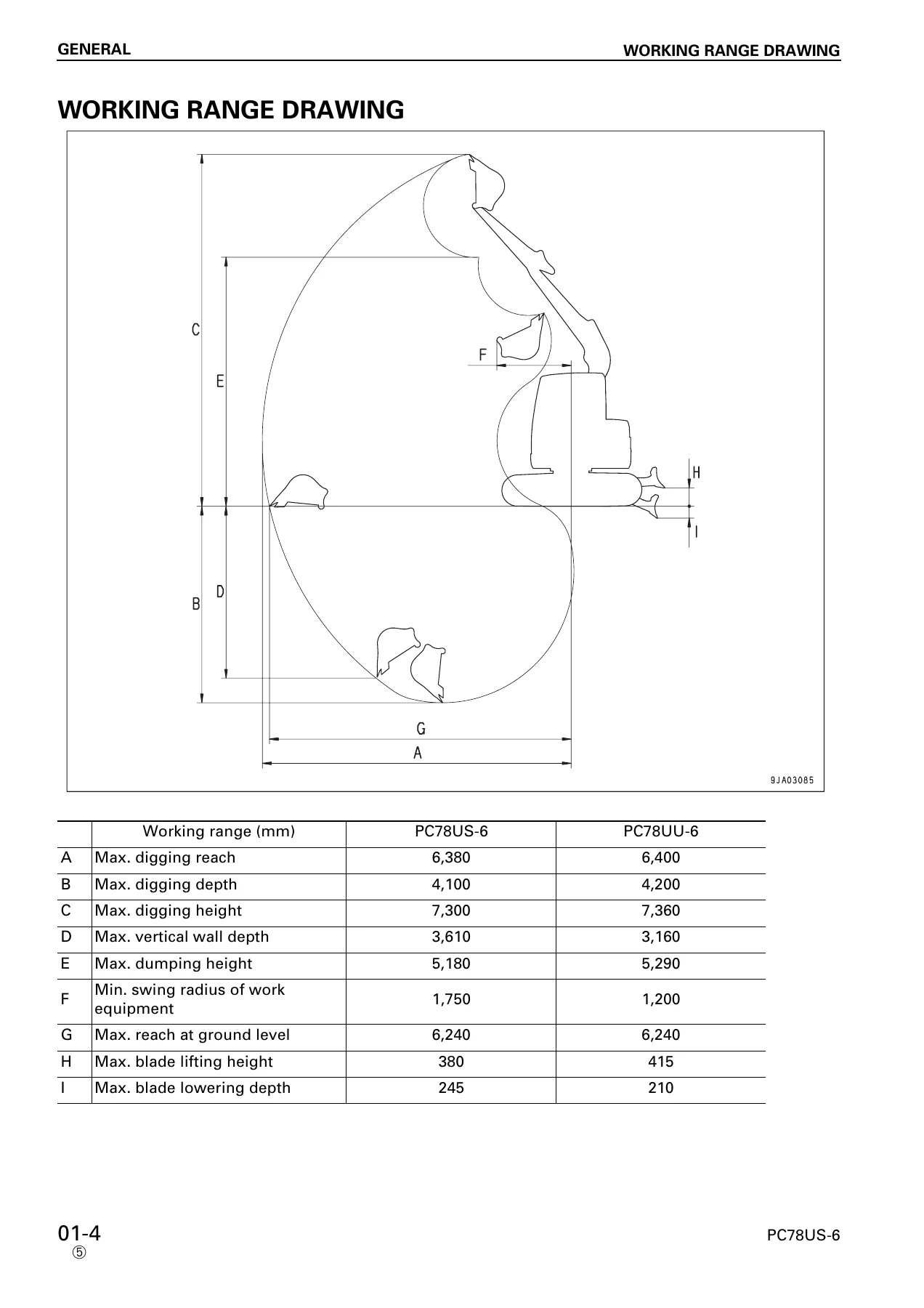
- Working range drawing
- Specifications
- Weight table
- List of lubricants and coolant
- 10 Structure and Function, Maintenance Standard
- Engine and pump control
- Hydraulic pump (LPD45 + 45)
- Control valve (CLSS system)
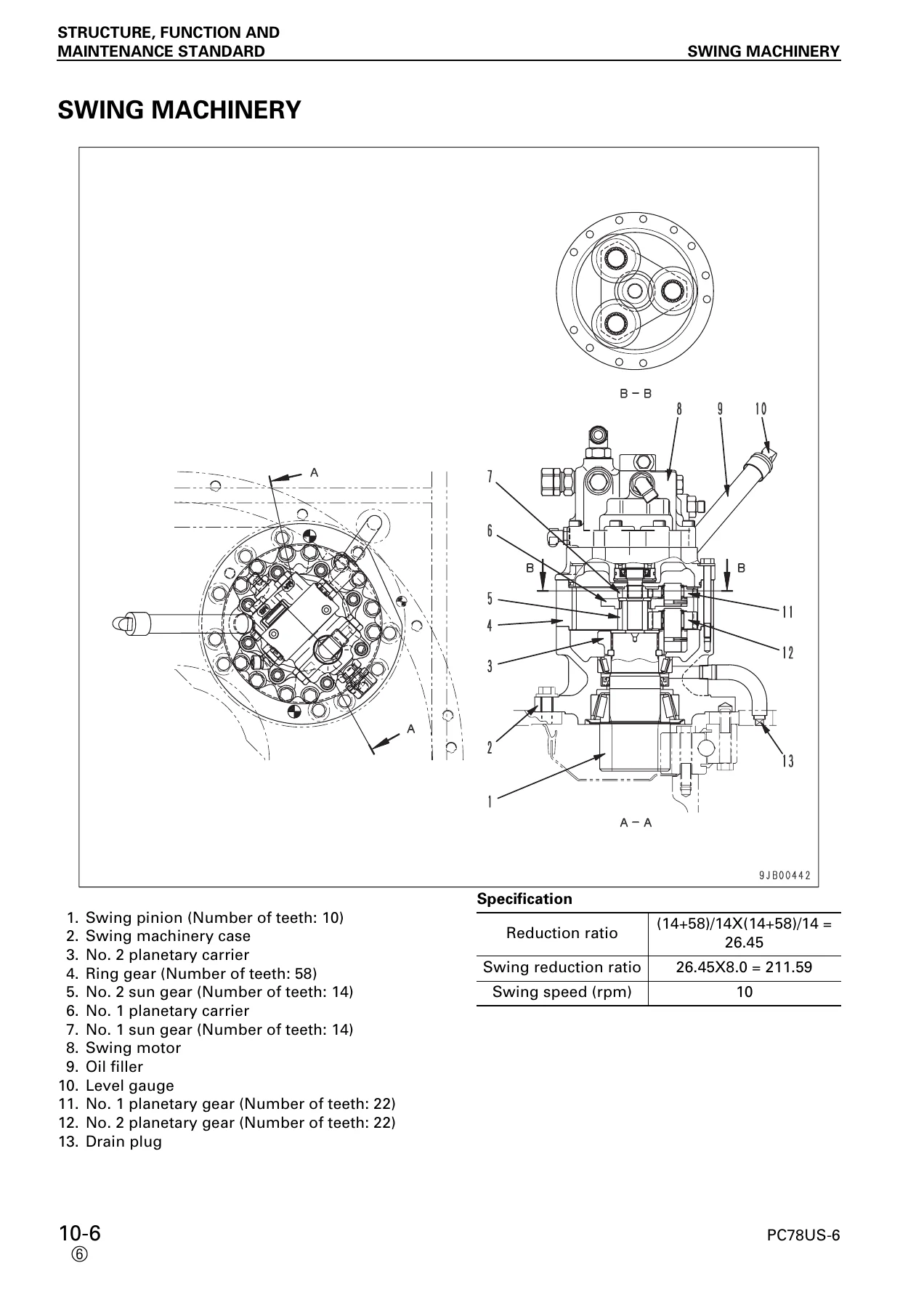
- Swing machinery and motor
- Travel motor (GM09VN-E)
- Work equipment cylinders
- Track frame, idler, sprocket, track shoe
- PPC valves (work equipment, travel, blade)
- Solenoid and EPC valves
- Monitor system, sensors, electric control system
- Work equipment dimensions
- 20 Testing and Adjusting
- Standard value tables (engine, chassis, electrical parts)
- Measuring engine speed, exhaust gas color, compression pressure, blow-by pressure
- Adjusting valve clearance, fuel injection timing, engine stop solenoid, fuel control linkage
- Testing and adjusting hydraulic pressure in work equipment, swing, and travel circuits
- Measuring LS differential pressure and adjusting LS valve
- Adjusting PC valve, testing TVC-EPC solenoid output pressure
- Measuring control circuit pressure, PPC valve output pressure
- Testing travel deviation, hydraulic drift, oil leakage
- Releasing residual pressure, bleeding air from hydraulic circuit
- Testing clearance of swing circle bearing
- Testing and adjusting track shoe tension
- Troubleshooting (N, E, C, F, H, M modes)
- Connector types and mounting locations
- Connection table for connector pin numbers
- 30 Disassembly and Assembly
- Removal and installation of counterweight, injection pump, cylinder head, main pump, control pump, engine, hydraulic oil cooler, radiator
- Swing motor and swing machinery assembly
- Center swivel joint assembly
- Control valve assembly
- Work equipment PPC valve, travel PPC valve
- Hydraulic tank, fuel tank, controller, monitor panel
- Air conditioner unit, operator’s cab, floor frame, revolving frame, swing circle
- Work equipment assembly, first boom, second boom, offset bracket
- Track shoe, rubber shoe, final drive, idler, recoil spring, track roller
- Hydraulic cylinder assembly
- 50 Other Specifications (PC78US-6 For Norway)
- Specification dimensions drawing
- Working range drawing
- Specifications and weight table
- Arrangement of hydraulic components
- Boom hydraulic anti-burst valve
- Electric control system and general system diagram
- Overload alarm function and pressure switch
- Meter display unit
- Troubleshooting for controller pump control system and machine monitor system
- 90 Others
- Hydraulic circuit diagrams (blade-less specification, additional attachment circuit, blade specification, Norway specification, PC78UU-6)
- Electrical circuit diagrams (PC78US-6 4001-5500, PC78US-6 5501 and up, PC78US-6 Norway specification, PC78UU-6 22832-23500, PC78UU-6 23501 and up)
This shop manual is the reference Komatsu distributes to service technicians for the PC78US-6 and PC78UU-6. It is divided so that the structure and function of each component is explained first, then testing and adjusting procedures, then disassembly and assembly, and finally the hydraulic and electrical circuit diagrams. The maintenance standard section gives judgement criteria for inspecting disassembled parts, including wear limits, clearances, and service limits.
The testing and adjusting section alone runs to over 500 pages, covering everything from measuring engine compression to diagnosing the CLSS (Closed center Load Sensing System) hydraulic circuit. The troubleshooting section is organized by diagnostic mode (N, E, C, F, H, M) and includes service codes and monitoring codes for the controller and monitor panel.
What This Shop Manual Covers
Engine and Pump Control
The manual covers the 4D95LE-2 and S4D95LE-3-A engines in the context of the machine, including the engine and pump compound control function, TVC-EPC valve adjustment, and the governor control system. Engine specifications, torque values, and service limits are provided in the standard value tables.
Hydraulic System
The hydraulic system section covers the variable-capacity piston pump (LPD45 + 45), the CLSS control valve, LS valve, PC valve, TVC valve, and the pump merge-divider valve. The control valve section includes pressure compensation valves, unload valves, LS bypass plugs, travel junction valves, logic valves, and boom hydraulic drift prevention valves. Complete hydraulic circuit diagrams are provided in Section 90.
Swing and Travel
The swing machinery section covers the reduction gears, swing motor, brake valve, and safety valve. The travel motor section covers the GM09VN-E variable-capacity piston motor, including the 2-stage travel speed changeover mechanism, parking brake, and counterbalance valve. Maintenance standards for backlash, clearances, and wear limits are provided.
Work Equipment
Boom, arm, bucket, offset (PC78UU-6), and blade cylinders are covered with dimensional drawings, clearance specifications, tightening torques, and disassembly/assembly procedures. The work equipment section also covers the PPC valves, EPC valves, and the interference prevention system for the PC78UU-6.
Undercarriage
Track frame, idler cushion, recoil spring, track roller, carrier roller, sprocket, and track shoe (city pad shoe, road liner, triple shoe, rubber shoe) are covered with wear limits and maintenance standards. Track shoe tension adjustment and final drive removal/installation are included.
Electrical System
The electric control system section covers the controller, monitor panel, sensors, PPC oil pressure switches, potentiometers, and solenoid valves. Electrical circuit diagrams are provided for each model and serial number range. The self-diagnostic function, user codes, service codes, and monitoring codes are explained in detail.
Troubleshooting
The troubleshooting section is organized by system: communication system (N mode), governor control system (E mode), pump control system (C mode), input signal system (F mode), hydraulic and mechanical systems (H mode), and machine monitor system (M mode). Each failure mode has a diagnostic flow with causes and remedies.
Why This Manual Matters
When servicing a Komatsu PC78US-6 or PC78UU-6, using the correct specifications and procedures is critical. The hydraulic system operates at pressures up to 26.5 MPa (270 kg/cm²), and the CLSS system requires precise adjustment of the LS valve and PC valve to maintain proper pump control. Incorrect adjustment can lead to poor performance, overheating, or component damage.
This shop manual provides the actual Komatsu service procedures, torque values, wear limits, and diagnostic flowcharts that Komatsu technicians use. Whether you are rebuilding a hydraulic cylinder, adjusting the LS differential pressure, diagnosing a controller fault code, or replacing a final drive, the manual gives you the sequence, the specifications, and the judgement criteria.
Who This Manual Is For
This manual is for mechanics, technicians, and owner-operators who service and repair the Komatsu PC78US-6 and PC78UU-6. It assumes familiarity with basic mechanical and hydraulic principles. The testing and adjusting section references special tools (with Komatsu part numbers) that are listed in the special tool list.
Instant PDF Delivery
This Komatsu PC78US-6 PC78UU-6 shop manual is delivered as a PDF download immediately after payment. There is no shipping, no waiting for a physical book, and no risk of a lost or damaged package. The PDF can be viewed on any device — computer, tablet, or smartphone — and you can print the pages you need for the workshop. Whether you need the full 785-page manual for a complete overhaul or just the hydraulic circuit diagram for a specific repair, the file is yours to keep and reference as often as you need.
Reviews
There are no reviews yet.