
Komatsu PW140-7 Wheeled Excavator Shop Manual (VEBM410101) – PDF Workshop Manual Download
Original price was: $67.95.$44.95Current price is: $44.95.
Complete 1,144-page Komatsu PW140-7 wheeled excavator Shop Manual VEBM410101. Covers engine, hydraulics, swing, transmission, axles, brakes, electrical and full disassembly for serial H55051 and up.
Description
Komatsu PW140-7 Shop Manual – VEBM410101
The Komatsu PW140-7 Shop Manual with document number VEBM410101 is the full workshop reference for the PW140-7 wheeled hydraulic excavator, covering serial number H55051 and up. At 1,144 pages, this is the same manual the workshop uses to test, adjust, disassemble, assemble and diagnose the machine — from the SAA4D107E engine and hydraulic pump through the swing machinery, transmission, axles, braking, steering and electrical control system. The file is delivered as a single PDF, ready to open on any device.
File Details
- Manual type: Shop Manual (service / workshop)
- Brand: Komatsu
- Model: PW140-7
- Serial number: H55051 and up
- Document number: VEBM410101
- Language: English
- Page count: 1,144
- File format: PDF
- Publication date: 2009-08
Chapters Covered
The Komatsu PW140-7 Shop Manual is organised into the standard Komatsu section numbering used across the 00 to 90 range:
- 00 – Foreword
- 01 – General
- 10 – Structure, Function and Maintenance Standard
- 20 – Testing and Adjusting
- 30 – Disassembly and Assembly
- 90 – Other
01 – General
The opening section sets out the machine’s specification dimension drawings for both the 1-piece and 2-piece boom configurations, working ranges for the 2,100 mm, 2,500 mm and 3,000 mm arms, operating weight, bucket capacity, engine performance figures, hydraulic pump and cylinder specifications, and a full component weight table. It also lists the fuel, coolant and lubricant capacities for the engine oil pan, swing machinery case, hydraulic tank, fuel tank, cooling system, axles, transmission and hubs. Use this section for machine identification and for filling out the fluids correctly.
10 – Structure, Function and Maintenance Standard
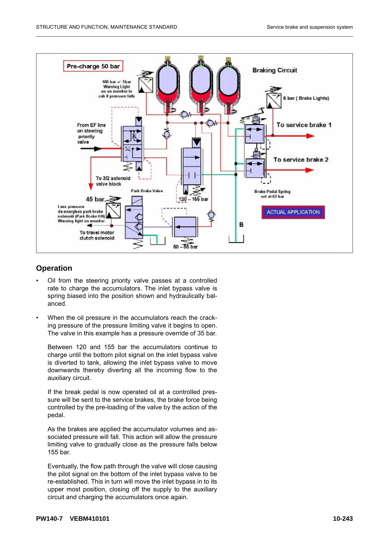
This is the technical heart of the PW140-7 workshop manual. It explains how each system is built and how it works: engine-related parts, the combination radiator / oil cooler / charge air cooler, the power train layout, swing circle, swing machinery and motor with the swing lock and relief valve function, undercarriage, transmission with its high / low clutch packs, quick coupler control valve, ATT EPC valve assembly, travel motor including counterbalance and brake valves, clutch control circuit, axles, suspension lock cylinder, braking system, brake / steer pump, priority valve, power brake valve, accumulators, steering system and Orbitrol valve, hydraulic tank, the HPV variable displacement piston pump with its LS, PC and EPC control valves, the full CLSS (Closed centre Load Sensing System) explanation including unload valve, pressure compensation, boom and arm regeneration circuits, swing bleed valve and LS select valve, centre swivel joint, PPC pedals and valves, solenoid valve block, boom safety valve, hydraulic cylinders, work equipment dimensions, air conditioner piping, and the electrical control system with machine monitor, KOMTRAX terminal system and all sensors. Maintenance Standard tables inside this chapter give standard sizes, standard clearances, repair limits and remedies for the parts discussed.
20 – Testing and Adjusting
Every test and adjustment you would carry out on this machine is covered here in detail. It starts with standard value tables for engine-related parts and chassis-related parts (engine speeds, spool strokes, lever travel, operating forces, hydraulic pressures, swing times, travel speeds, work equipment speeds, time lag and internal leakage). It then walks through measuring engine speed, boost pressure, exhaust gas colour, valve clearance, compression pressure, blow-by pressure, engine oil pressure, handling and releasing the fuel system, fuel pressure, fuel return rate and leakage, air conditioner belt tension, fan belt replacement, swing circle bearing clearance, hydraulic oil pressure in the work equipment, swing and travel circuits, control circuit oil pressure, PC and LS valve control oil pressure, solenoid valve output pressure, PPC valve output pressure, PPC valve adjustment, quick coupler control valve output pressure, travel motor relief pressure, propshaft speed, transmission clutch control circuit, hydraulic drift, releasing residual pressure, oil leakage measurement, air bleeding of all parts, diode inspection, the special functions of the monitor panel, the failure code table, the service menu, and the KOMTRAX terminal lamp indications. The Troubleshooting chapters are then split by type: failure code troubleshooting, E-Mode electrical troubleshooting, error checking of items without monitor codes, and H-Mode hydraulic and mechanical troubleshooting. There is also an S-Mode engine troubleshooting section covering poor starting, no start, poor pick-up, engine stop, rough running, low power, black exhaust, oil consumption, oil contamination, fuel consumption, coolant problems, oil pressure drop, overheating, abnormal noise and vibration.
30 – Disassembly and Assembly
The teardown chapter gives step-by-step procedures with tightening torques, sealant and adhesive callouts, special tool references and weights for every major component. It covers the fuel supply pump and fuel injector assemblies, front and rear oil seals, cylinder head assembly, combination cooler assembly, engine and hydraulic pump assembly, engine hood, travel motor, swing motor and swing machinery, front axle, rear axle and transmission, propshaft, wheels, suspension lock cylinder, outriggers, dozer blade, swing circle, revolving frame, centre swivel joint, fuel tank, hydraulic tank, control valve, LS separation valve, pressure compensation valve, main relief valve, LS and PC EPC valves, PPC valve block, hydraulic pump input shaft oil seal, work equipment PPC valve, hydraulic cylinders, monoboom and 2-piece boom work equipment, air conditioner unit, counterweight, operator cab, monitor, pump controller and the KOMTRAX terminal.
90 – Other
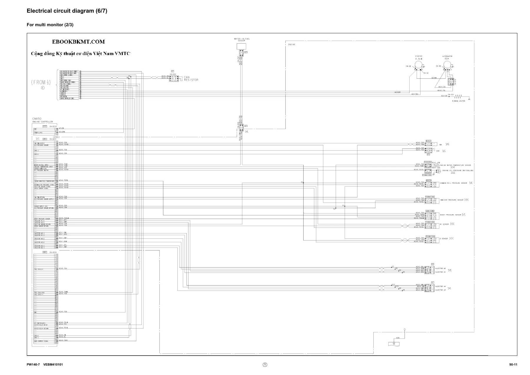
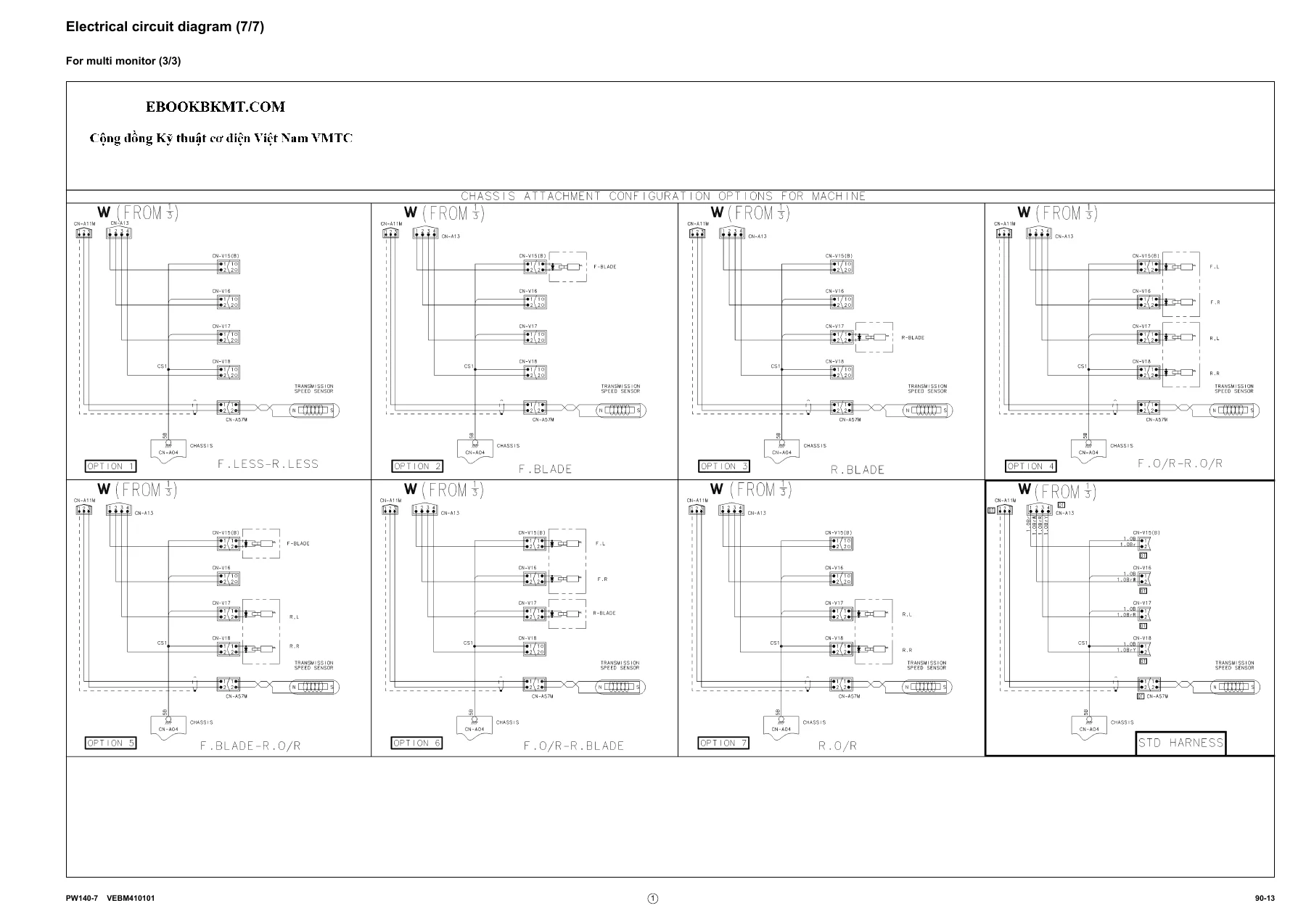
This closing section holds the large format reference drawings: the three-sheet hydraulic circuit diagram and the seven-sheet electrical circuit diagram including the multi-monitor sheets, plus the machine control system diagrams referenced from chapter 10.
Why This Komatsu PW140-7 Shop Manual Matters
The PW140-7 is a machine where systems overlap — hydraulic pressure control interacts with the CLSS, the electronic control system talks to the pump controller and engine controller over CAN, and the transmission, axles and brakes share circuits with the steering. Guessing at a diagnosis is expensive. This PW140-7 service manual PDF gives you the pump pressure, LS differential pressure, spool stroke, engine speed, relief pressure and oil leakage figures you need to know whether a component is actually out of specification, plus the flow paths that tell you why.
For rebuilds, the Disassembly and Assembly chapter carries the torques, sealants, assembly order, shim measurement procedures and press-fit dimensions for swing machinery, transmission clutch packs, epicyclic reduction gears, brake carriers, beam trumpets, differential units and pinion groups. For fault-finding, the four troubleshooting sections and the failure code tables let you go from a symptom or a code on the monitor panel straight to the circuit diagram and the standard value.
IMAGES PREVIEW
Whether you are servicing a single machine or running a fleet, having the Komatsu PW140-7 repair manual on hand means you can look up a specification, verify a pressure, or plan a teardown without waiting on the workshop. This is a digital PDF download — there is no shipping and no waiting. Open it on a laptop, tablet or phone in the workshop, print the pages you need for the job, and keep the full manual for reference. Your copy is available instantly after checkout.

Reviews
There are no reviews yet.