
Komatsu WA320-8 Wheel Loader Shop Manual CEBM031204 – PDF Download
Original price was: $79.95.$49.95Current price is: $49.95.
Complete Komatsu WA320-8 Wheel Loader Shop Manual, document CEBM031204, covering serial numbers A38001–A39471 with the SAA6D107E-3 engine. Full specifications, structure and function, testing and adjusting, troubleshooting, disassembly and assembly, maintenance standards, and hydraulic and electrical circuit diagrams. Instant PDF download.
Description
Komatsu WA320-8 Wheel Loader Shop Manual — CEBM031204
This is the complete Komatsu WA320-8 Wheel Loader Shop Manual, document number CEBM031204, covering machines in serial number range A38001 through A39471 and powered by the Komatsu SAA6D107E-3 diesel engine. It is a full, multi-thousand-page service publication spanning specification tables, structure-and-function theory, step-by-step testing and adjusting procedures, complete troubleshooting by failure code, disassembly and assembly instructions, maintenance standards, and full hydraulic and electrical circuit diagrams.
Every procedure is written around the WA320-8 and the SAA6D107E-3 engine configuration. Torque values, test conditions, component locations, and acceptance criteria are given for the serial-number range printed on the cover, so the manual matches the machine in front of you rather than a generic approximation.
File Details
- Manual type: Shop Manual
- Brand: Komatsu
- Model: WA320-8 Wheel Loader
- Engine: SAA6D107E-3
- Serial number range: A38001 – A39471
- Document number: CEBM031204
- Language: English
- Page count: Over 2,000 pages
- File format: PDF
Chapters Covered
- 00 — Index and Foreword
- 01 — Specifications
- 10 — Structure and Function
- 20 — Standard Value Table
- 30 — Testing and Adjusting
- 40 — Troubleshooting
- 50 — Disassembly and Assembly
- 60 — Maintenance Standard
- 80 — Appendix (Air Conditioner System)
- 90 — Circuit Diagrams
00 Index and Foreword
Front matter with the abbreviation lists used throughout the manual, safety notices for operation, precautions to prevent fire, precautions for handling DEF and AdBlue, general precautions for hydraulic, electrical, fuel, and intake system work, a standard tightening torque table for metric and unified threads, and a conversion table between mm and in, kg and lb, kgfm and lbft, kgf/cm² and lb/in², and Fahrenheit and Celsius.
01 Specifications
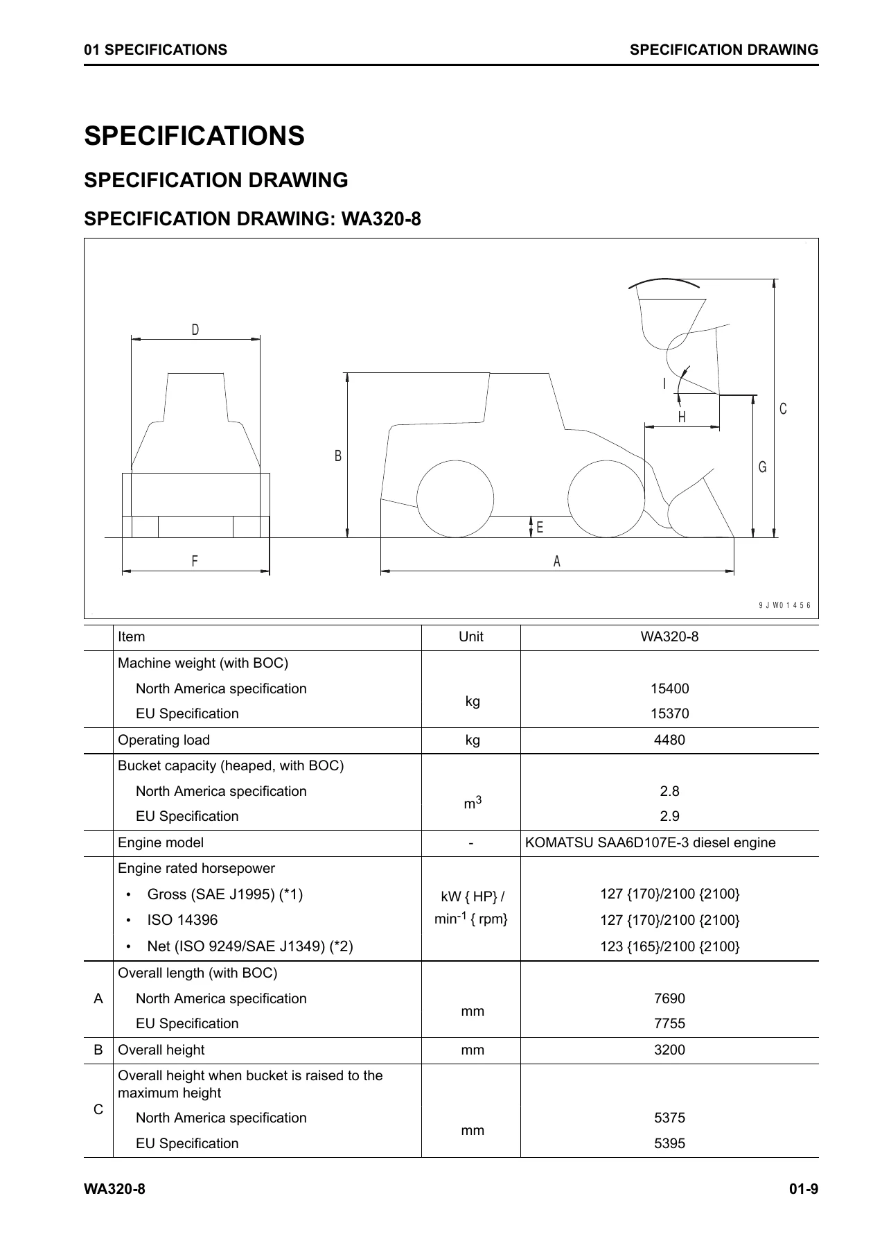
Machine weight, bucket capacity, rated horsepower, overall dimensions, travel speeds, tire and rim sizes, brake and steering specifications, cylinder bores and strokes, pump displacements and set pressures. A separate weight table lists dry weights for major components — engine assembly, HST pump, HST motors, transfer, axles, boom, bucket, counterweight — which is useful when planning a lift or a haul. Fluid capacities, ambient temperature ranges, and the recommended Komatsu fluids for engine oil, power train oil, axle oil, grease, coolant, and DEF are all included.
10 Structure and Function
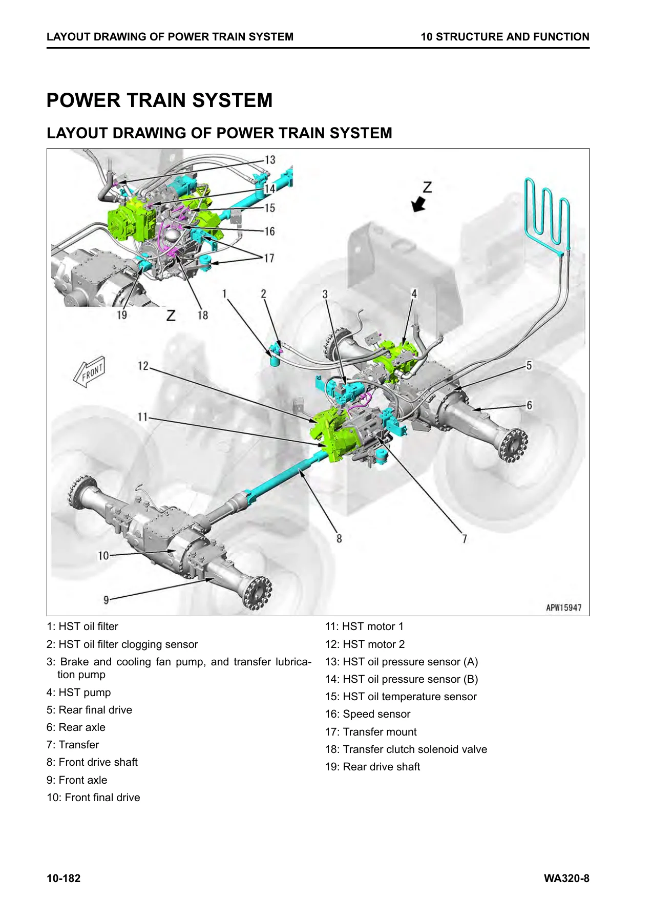
Explains how the machine actually operates. Covers the Urea SCR system and its AdBlue/DEF circuit, the engine system and engine control, the cooling fan control, the CLSS hydraulic system, the HST power train and its control, the work equipment system (bucket positioner, fork positioner, remote boom positioner, ECSS), the steering system, the brake system, and the auto-greasing system. Component drawings, system diagrams, and sectional views accompany the text so oil flow, electrical signals, and mechanical force paths can be traced through the machine.
20 Standard Value Table
The reference for judging whether a component is within specification. Standard values for new machines and repair limits are listed for engine performance (speeds, boost pressure, exhaust gas temperature and colour, compression, blowby), lubrication, cooling, and machine systems including HST oil pressure, brake accumulator charge pressures, work equipment relief pressure, cooling fan speeds, and pump pressures. This chapter is used together with Chapter 30 to decide what needs adjustment or replacement.
30 Testing and Adjusting
The procedures technicians perform in the field: testing engine speed, boost pressure, exhaust gas temperature and colour, valve clearance, compression pressure, blowby pressure, engine oil pressure, EGR and VGT oil pressure, fuel pressure, fuel discharge and return rates, SCR-related functions, HST oil pressure, transfer clutch control pressure, steering circuit pressure, brake accumulator charge pressure, work equipment oil pressure and PPC pressure, cooling fan speed, and ECSS accumulator nitrogen gas pressure. Each section lists the tools needed, the measurement conditions, and the acceptance criteria.
40 Troubleshooting
Split into troubleshooting by failure code (with full failure-code tables and cause lists), electrical system troubleshooting (E-mode), hydraulic and mechanical troubleshooting (H-mode), and engine troubleshooting (S-mode). Failure codes are indexed by code and by symptom, with step-by-step diagnostic procedures, connector pin data, and circuit diagrams. For most real repairs, this is where the work starts.
50 Disassembly and Assembly
Component-level removal, installation, disassembly, and assembly procedures for the engine and cooling system, the power train (HST pump, HST motors, transfer, axles), the hydraulic system (hydraulic tank, control valve, quick coupler LS pressure rise valve), work equipment (linkage and cylinders), the operator’s cab and floor frame, and the electrical system. Tightening torques, special tools, coating materials, and lubricants are specified at each step.
60 Maintenance Standard
Maintenance standards for each major component — dampers, cooling fan motors, drive shafts, transfer, front and rear axles, torque proportioning and limited slip differentials, final drives, steering column, priority valve, steering cylinder, secondary steering valve, brake circuit accumulator charge valve, slack adjuster, brakes, parking brake, hydraulic pumps, control valve, self-pressure reducing valve, multifunction mono-lever PPC valve, work equipment lock solenoid valve, and work equipment linkage — with the wear limits and adjustment criteria that define when a part needs repair or replacement.
80 Appendix
Covers the air conditioner system: refrigerant precautions, component layout, specifications, refrigeration cycle, circuit diagram and connector pin arrangement, self-diagnosis function, temperature control check, vent mode changeover, fresh/recirc air changeover, evaporator temperature sensor testing, relay testing, and troubleshooting charts.
90 Circuit Diagrams
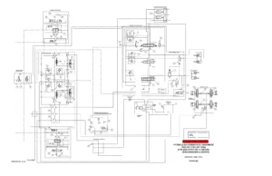
Full hydraulic circuit diagrams and electrical circuit diagrams of the machine, with a symbols legend and connector arrangements. These are the drawings needed when tracing a specific circuit fault through the machine harness or hydraulic piping.
What This Manual Lets You Do
With the Komatsu WA320-8 Shop Manual (CEBM031204) in hand, you can diagnose and repair the WA320-8 using the same procedures and specifications the machine was designed around. This is not a generic guide — every procedure in the manual is specific to the WA320-8 with the SAA6D107E-3 engine and serial range A38001 through A39471.
You can pull a specific failure code and follow the cause table straight to the connector or component to test, without guessing. You can check compression, boost, and blowby to determine engine condition. You can set up and verify HST pressures, transfer clutch pressure, brake accumulator charge, and work equipment relief pressure. You can disassemble and reassemble a lift cylinder, bucket cylinder, transfer, axle, or HST pump with the correct tools, coatings, and torque values. And you can trace a circuit fault through the hydraulic and electrical circuit diagrams without pulling half the machine apart.
The value of a factory-level shop manual shows up in the small details: the exact tightening torque, the correct test condition, the clearance that tells you whether a part is worn, the connector pin that should have continuity. Without those, the job takes longer, costs more, and often comes back.
IMAGES PREVIEW
The manual is delivered as an instant PDF download after purchase — no shipping, no waiting for a printed book. It opens on any device (Windows, Mac, tablet, phone), you can print the pages you need for the shop floor, and you can keep the whole thing on a laptop or USB stick beside the machine. For a machine in the A38001–A39471 serial range, this is the documentation to keep on hand.

Reviews
There are no reviews yet.