
Komatsu WA380-6 KA Spec Wheel Loader Shop Manual SEN00769-02 PDF
Original price was: $59.95.$39.95Current price is: $39.95.
Complete Komatsu WA380-6 (KA Spec, serial 65001 & up) Shop Manual SEN00769-02. Covers engine, power train, steering, brakes, hydraulics, work equipment, cab, electrical, troubleshooting, disassembly & assembly, plus full diagrams. 1,332-page PDF for instant download.
Description
Komatsu WA380-6 KA Specification Shop Manual — SEN00769-02
This Komatsu WA380-6 KA Specification Shop Manual is the complete workshop-level service guide for the GALEO WA380-6 wheel loader, covering machines with serial numbers WA380-6 65001 and up. Published in 2006 under document number SEN00769-02, it brings together every major service discipline — engine and cooling, power train, steering, brakes, undercarriage, hydraulics, work equipment, cab, and electrical systems — into one massive reference. Whether you are diagnosing a fault code, measuring oil pressure, disassembling a clutch pack, or verifying a torque value, this manual gives you the procedures, specifications, and diagrams to do the job correctly.
File Details
- Manual Type: Shop Manual (Service, Repair & Maintenance)
- Brand: Komatsu
- Model: WA380-6 (KA SPEC.)
- Serial Numbers: WA380-6 65001 and up
- Document Number: SEN00769-02
- Language: English
- File Format: PDF
- Publication Date: 2006
- Page Count: 1,332 pages (bound as one complete shop manual PDF)
Chapters Covered
- 00 Index and Foreword
- 01 Specification
- 10 Structure, Function and Maintenance Standard
- 20 Standard Value Table
- 30 Testing and Adjusting
- 40 Troubleshooting
- 50 Disassembly and Assembly
- 90 Diagrams and Drawings
00 Index and Foreword
This opening section lists the full shop manual composition by Form Number, explains filing and revision procedures, and contains the foreword with general information. You get the safety notice, how-to-read-the-shop-manual guidance, explanation of terms for maintenance standards, handling instructions for electric equipment and hydraulic components, how to read electric wire codes, push-pull coupler disassembly and connection methods, a standard tightening torque table, and a conversion table. This is the orientation material that makes the rest of the manual usable and safe.
01 Specification
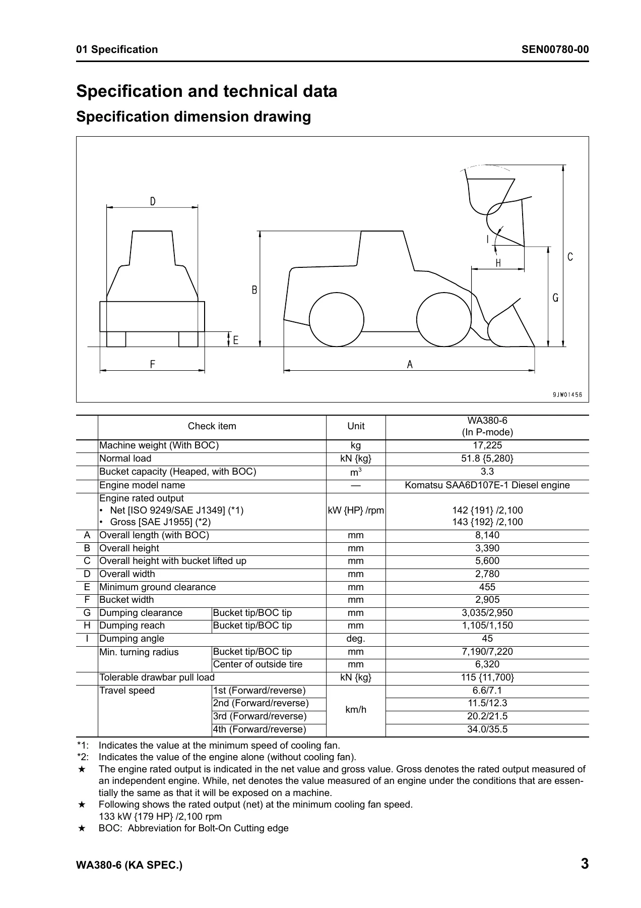
The specification chapter provides the machine dimension drawing, full specifications, a weight table, and a table of fuel, coolant, and lubricants. It details the WA380-6 in P-mode with machine weight, normal load, bucket capacity, engine rated output (net and gross), overall length, height, width, dumping clearance and reach, turning radius, travel speeds, and more. The weight table breaks down individual components — engine, cooling assembly, torque converter, transmission, drive shafts, axles, pumps, valves, cylinders, counterweight, lift arm, bucket, and cab — so you know exactly what you are lifting before you rig it.
10 Structure, Function and Maintenance Standard
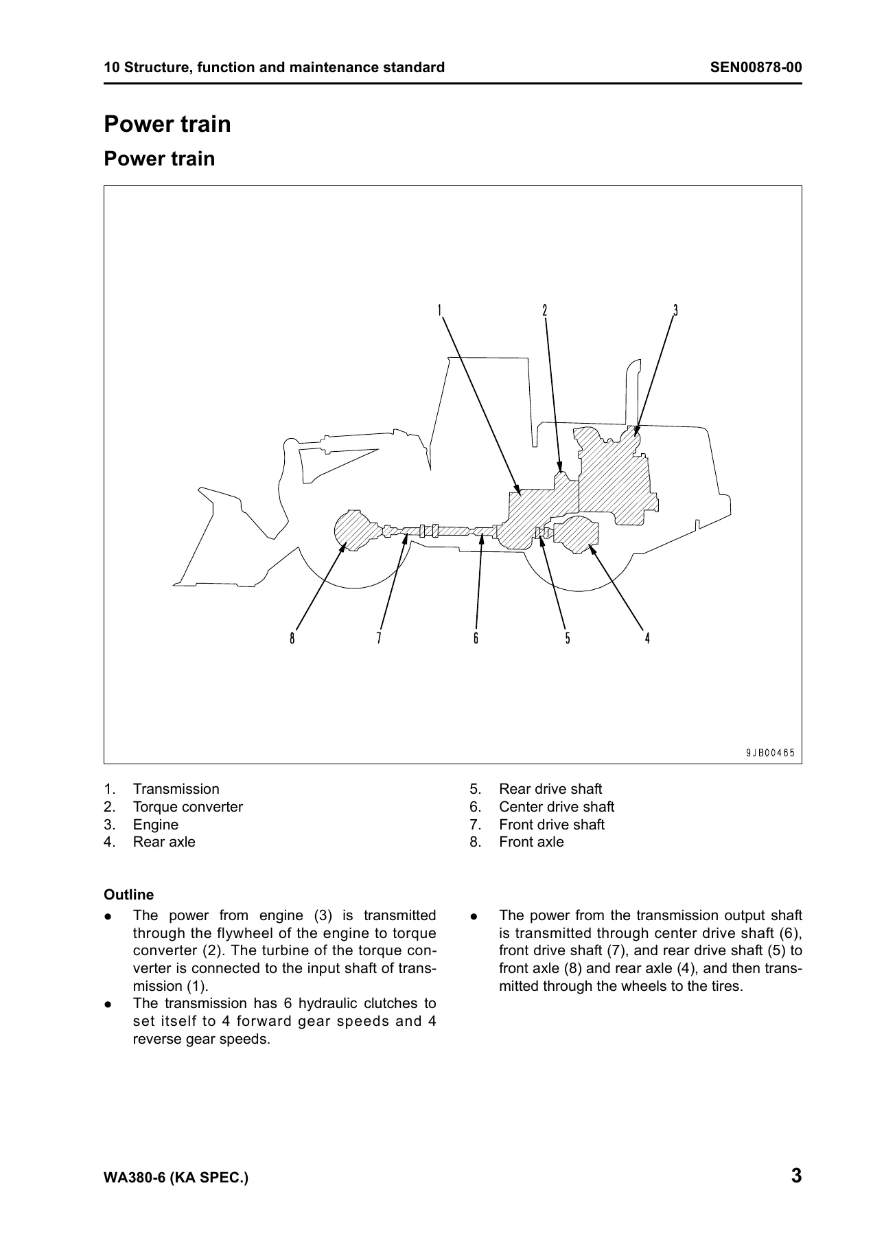
This is the largest chapter group. It explains how each system is built and how it works, with maintenance standards for wear limits and clearances. Engine and cooling system coverage includes engine mounts, transmission mounts, the cooling system layout, cooling fan pump and motor with servo valve, and maintenance standards. The power train section covers the torque converter (both standard and lockup clutch versions), transmission with 4 forward and 4 reverse speeds, flow control valve, ECMV (Electronic Control Modulation Valve) operation for gear speed and lockup clutches, main relief and torque converter relief valves, axle, differential, limited slip differential, and final drive. Steering system coverage includes the steering column, steering pump with LS and PC valve operation, steering valve, Orbit-roll valve, stop valve, steering relief valve, steering cylinder, emergency steering motor, and emergency steering pump. The brake system section details the charge valve, brake valve, accumulator, wheel brake, parking brake control, parking brake, parking brake solenoid valve, and emergency parking brake release valve. Hydraulic system Part 1 covers hydraulic piping, work equipment control lever linkage, hydraulic tank, breather, power train pump, work equipment pump, work equipment control valve, and the CLSS (Closed center Load Sensing System) with pressure compensation control. Hydraulic system Part 2 covers the PPC valve, stabilizer valve, and accumulators for PPC and ECSS circuits. Work equipment coverage includes linkage, bucket, bucket positioner and boom kick-out, and work equipment cylinders. Cab and attachments and the electrical system (Parts 1, 2 and 3) round out the section with machine monitor system, transmission controller, electric transmission control, KOMTRAX terminal, starting and stopping circuits, preheating, engine power mode, derating, automatic warm-up, parking brake circuit, and sensors.
20 Standard Value Table
The standard service value table gives you the new-machine standard values and service limit values for the engine and chassis. Engine rows cover high idle and low idle in E-mode and P-mode, exhaust temperature, boost pressure, exhaust gas color, valve clearance, blow-by pressure, oil pressure, oil temperature, and belt tension. Chassis rows cover directional lever, gearshift lever, work equipment control lever effort and stroke, steering wheel play and operating effort, frame clearance, accelerator pedal, brake pedal, tire and wheel lock ring, torque converter stall and hydraulic stall speeds, transmission and torque converter pressures, steering relief and control pressure, accumulator charge cut-in and cut-out, travel speeds, wheel brake and parking brake, PPC valve, work equipment relief and unload pressures, LS differential pressure, work equipment speed, hydraulic drift, and hydraulic drive fan. This is the chapter you reach for when you need to know whether a measurement is good or worn out.
30 Testing and Adjusting
The testing and adjusting chapters (Parts 1, 2 and 3) give you the tools, procedures, and measurement conditions for the full machine. Part 1 covers testing and adjusting tools, measuring engine speed, measuring exhaust gas color, adjusting valve clearance, measuring compression pressure, measuring blow-by pressure, measuring engine oil pressure, measuring intake air (boost) pressure, handling the fuel system, releasing residual fuel pressure, measuring fuel pressure, measuring fuel return rate and leakage, bleeding air from the fuel circuit, testing fuel system leakage, handling reduced cylinder mode and no-injection cranking, controller voltage circuit, air conditioner compressor belt tension, transmission speed sensor, directional lever, power train oil pressure (with a detailed 12-point measuring guide), flushing the torque converter and transmission circuit, moving the machine when the transmission valve is broken, steering stop valve, steering wheel, steering oil pressure, and bleeding air from the steering circuit. Part 2 covers the hydraulic drive fan, brake pedal and performance, accumulator charge pressure, wheel brake oil pressure, wheel brake disc wear, brake circuit bleeding, releasing residual brake accumulator pressure, parking brake performance and oil pressure, parking brake disc wear, manual parking brake release, work equipment control lever and PPC oil pressure, work equipment oil pressure, work equipment circuit bleeding and residual pressure release, bucket positioner and boom kick-out, proximity switch pilot lamp, diode testing, electrical troubleshooting preparation, KOMTRAX terminal start-up and lamp display, and machine monitor adjustment. Part 3 is the special functions of the machine monitor (EMMS) reference, including the Pm-clinic inspection table.
40 Troubleshooting
Troubleshooting is organized into code display, E-mode (electrical), H-mode (hydraulic and mechanical), and S-mode (engine). The general information chapter explains how to troubleshoot, what to test before you start, and how to use the connector pin number table and T-branch box/adapter table. The failure code display sections cover hundreds of codes for the transmission, engine, machine monitor, and sensors — from ECMV clutch fill signal faults and parking brake malfunctions through common rail pressure, injector, sensor power supply, CAN communication, and electrical system failures. Each code entry tells you the trouble, the controller action, what appears on the machine, related information, and possible causes with standard values in normal state. E-mode covers symptoms such as engine does not start, wiper, washer, lamps, turn signal, brake lamp, backup lamp and buzzer, horn, alarm buzzer, air conditioner, and KOMTRAX. H-mode covers machine does not start, torque converter lockup faults, slow travel, gear shift shocks and time lag, high torque converter oil temperature, steering faults (including joystick steering), wheel and parking brake faults, work equipment faults from lift arm and bucket issues through control lever effort and engine stall, ECSS faults. S-mode covers engine startability, smoothness, stops, output, exhaust smoke, oil consumption and contamination, fuel consumption, coolant, oil pressure, oil level, overheating, abnormal noise, and vibration.
50 Disassembly and Assembly
The disassembly and assembly chapters give you the special tools, coating materials, and step-by-step procedures for removing, installing, disassembling, and assembling major components. General information covers how to read the manual, the coating materials list, and the special tools list. Engine and cooling system procedures cover fuel supply pump, fuel injector, cylinder head, engine hood, radiator, air aftercooler, hydraulic oil cooler, engine assembly, cooling fan and fan motor, and fuel tank. Power train procedures cover torque converter and transmission removal, torque converter disassembly (standard and lockup), transmission disassembly, clutch pack disassembly, parking brake, front and rear axle, axle housing, and differential. Steering system covers the steering demand valve. Brake system covers parking brake discs and plates. Undercarriage and frame covers the center hinge pin and counterweight. Hydraulic system covers work equipment control valve, power train and work equipment pumps, steering and cooling fan pumps, and hydraulic tank. Work equipment covers the work equipment assembly and hydraulic cylinders. Cab and attachments covers the operator’s cab and floor frame, glass, and air conditioner unit. Electrical system covers the engine controller.
90 Diagrams and Drawings
The diagrams and drawings chapter gives you the power train hydraulic circuit diagram (for both without and with lockup clutch), the full hydraulic circuit diagram, and the electrical circuit diagrams in two parts. These are the fold-out style schematics you need when tracing a circuit, identifying a connector, or understanding how oil flows through the transmission, steering, brake, and work equipment systems.
Why This Komatsu WA380-6 Shop Manual Matters
The WA380-6 is a production wheel loader, and production equipment does not wait. When a transmission starts slipping, a lift arm drifts, or the machine throws a failure code, you need the correct torque, the correct pressure, and the correct procedure — not a guess. This shop manual gives you the measurement conditions for every pressure check, the standard value and the service limit, and the troubleshooting path that leads to the failed component instead of replacing parts until something works. It covers the SAA6D107E-1 diesel engine, the 4-speed forward and 4-speed reverse transmission with ECMV clutch control, the CLSS hydraulic system with LS and PC valve regulation, the wet-type multi-disc brakes, the Orbit-roll steering valve, the ECSS ride control system, and the machine monitor network including the transmission controller and KOMTRAX terminal. If you service, repair, or maintain a WA380-6, this is the reference that tells you what to do and what to measure.
IMAGES PREVIEW
Instant PDF Delivery
This Komatsu WA380-6 Shop Manual is delivered as an instant PDF download — no shipping, no waiting. The file works on any device: desktop, laptop, tablet, or phone. You can read it in the workshop, print the pages you need for the job, and keep the complete manual on hand for the next machine. When you need the procedure now, the PDF is one click away.

Reviews
There are no reviews yet.