
★ TRUSTED BY 321,897+ PROFESSIONALS WORLDWIDE
🏒
Trusted Business
Verified & Licensed
πŸ›‘οΈ
Virus Free Files
100% Safe Downloads
πŸ”’
Secure Payment
SSL Protected
⚑
Instant Delivery
Available Immediately
Sale!

Komatsu WA380-6 Wheel Loader Operation and Maintenance Manual – PDF

Original price was: $39.95.Current price is: $23.95.

Complete Komatsu WA380-6 wheel loader operation and maintenance manual covering the machine monitor, controls, work operations, maintenance schedules, service procedures, capacities, tightening torques and specifications in one PDF.

⚑
Instant PDF Download
Available immediately
πŸ’Ύ
Save to Your Device
Download & keep forever
πŸ›‘οΈ
Antivirus Scanned
100% virus-free
🌍
Trusted Worldwide
175,000+ customers

Description

Komatsu WA380-6 Wheel Loader Operation and Maintenance Manual

This Komatsu WA380-6 Wheel Loader Operation and Maintenance Manual is the complete reference for anyone running, servicing or repairing a WA380-6. It walks through the machine from the operator’s seat outward: how the monitor and switch panels work, how to check and start the engine, how to travel and work the loader safely, and how to keep the machine in specification through scheduled maintenance. The same document also carries the shop-level detail a technician needs, including tightening torques, fluid capacities, wear limits and step-by-step replacement procedures.

File Details

  • Manual type: Operation and Maintenance Manual
  • Brand: Komatsu
  • Model: WA380-6 Wheel Loader
  • Language: English
  • Page count: 380 pages
  • File format: PDF
  • Publication number: A53001-UP

Chapters Covered

  • Introduction β€” foreword, safety information, approved and non-approved uses, visibility standard, product identification, serial numbers and dealer information
  • Safety β€” safety and warning decals and their locations, general safety rules and precautions, unauthorized modifications, fire and explosion prevention, mounting and dismounting, inside the operator’s compartment, ROPS precautions, emergency escape, crush and pinch-point dangers, exhaust gas ventilation, rules for travel, working near high-voltage cables, travel on slopes, parking the machine, maintenance safety, high-pressure hoses, high-pressure fuel and oil, accumulators and gas springs, waste disposal, tire inflation and air conditioner maintenance
  • Operation β€” general view of the machine, controls and gauges, machine monitor, switch panel, explanation of components, types of warnings, central warning lamp, character display, action code and failure code display, filter and oil replacement time display, caution and pilot lamps, gauges, other monitor functions, security locks and safety features, machine features, electrical (fuses, slow-blow fuses, power outlet), work operations, walk-around check, checks before starting the engine, starting the engine in normal and cold weather, automatic warming-up, breaking in the machine, checks after starting, normal operation, stopping the engine, moving and stopping the machine, changing gear speed and direction, turning, emergency steering, operation of work equipment, digging, loading, leveling and load-and-carry operations, handling blasted rock, adjusting work equipment, removing and installing the bucket, parking and locking the machine, handling tires, transportation, lifting, cold weather operation, long-term storage and troubleshooting
  • Maintenance β€” guides to maintenance, outlines of service, wear parts list, recommended fuel, coolant and lubricants with ambient temperature chart, biodiesel usage, standard tightening torques for bolts and nuts and taper seals, periodic replacement of safety-critical parts with a full safety-critical parts list, maintenance schedule chart and service procedures from initial 250 hours through every 8000 hours
  • Specifications β€” machine weight, bucket capacity, engine model, flywheel horsepower, overall dimensions, dump angle, turning radius, permissible towing load and travel speeds
  • Options and Attachments β€” bucket and tires, torque converter lockup, joystick steering system, AM/FM radio cassette stereo sound system, automatic air conditioner, multi-function lever and machines equipped with KOMTRAX

What makes this Komatsu WA380-6 Wheel Loader Operation and Maintenance Manual useful is that it treats the machine as one system rather than a pile of separate parts. The operator’s section explains what every lamp, gauge and action code on the machine monitor means, so a warning is not just a light but a specific instruction β€” E03 means stop immediately and read the failure code, E02 means a temperature problem that has to be brought back into the white range, E01 means a maintenance or fluid-level item. The maintenance section then connects those warnings to real procedures: which filter, which fluid, which interval, which torque value. Around 380 pages of material means the digging, loading and leveling techniques, the travel rules, the safety-critical parts replacement intervals and the service schedule are all in the same file rather than scattered across separate publications.

Complete PDF Bookmark Tree

Complete Bookmarks

The complete bookmarks in the β€œKomatsu WA380-6 Wheel Loader Operation and Maintenance Manual – PDF” are as follows:

INTRODUCTIONp. 3
FOREWORDp. 4
SAFETY INFORMATIONp. 5
APPROVED AND NON-APPROVED USESp. 6
Approved Functionsp. 6
Non-Approved Functionsp. 6
VISIBILITY STANDARDp. 7
Visibility in Immediate Areap. 7
12-M Radius Visibilityp. 7
PRODUCT IDENTIFICATIONp. 8
Directions of Machinep. 8
Machine Serial Numberp. 9
Engine Serial Number, EPA Regulationsp. 9
Service Meter Locationp. 10
SERIAL NUMBERS AND DEALER INFORMATIONp. 11
TABLE OF CONTENTSp. 13
SAFETYp. 25
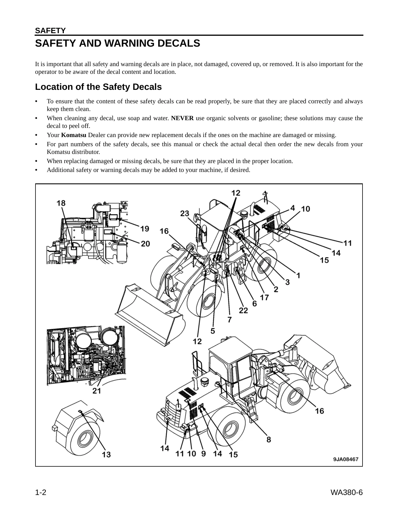
SAFETY AND WARNING DECALSp. 26
Location of the Safety Decalsp. 26
Safety Labelsp. 27
GENERAL SAFETY RULES AND PRECAUTIONSp. 34
General Safety Rulesp. 34
Unauthorized Modificationsp. 34
General Safety at Job Sitep. 35
Working on Loose Groundp. 35
Safety Featuresp. 35
Personal Protective Equipmentp. 36
Fire and Explosion Preventionp. 36
Fire Caused by Fuel, Oil, Antifreeze, or Window Washer Fluidp. 36
Fire Caused by Accumulation of Flammable Materialp. 37
Fire Caused by Electrical Wiringp. 37
Fire Caused by Hydraulic Linesp. 37
Fire Caused by Lighting Equipmentp. 37
Action if Fire Occursp. 37
Fire Extinguisher and First Aid Kitp. 38
Mounting and Dismountingp. 39
Inside Operator’s Compartmentp. 40
Precautions When Standing Up from Operator’s Seatp. 40
Precautions When Using ROPSp. 41
Emergency Escape from Operator’s Cabp. 41
Leaving Operator’s Compartmentp. 42
Precautions When Cleaning Cab Glassp. 43
Asbestos Hazard Alertp. 43
Crush or Pinch-Point Dangersp. 44
Precautions for Ventilation Exhaust Gasp. 44
PRECAUTIONS BEFORE STARTING OPERATIONSp. 45
Pre-Operational Checksp. 45
Ensure Good Visibilityp. 45
Confirmation of Marksp. 45
Precaution for Warning Tagp. 46
Checks Before Starting Engine, Adjustmentsp. 47
Precautions When Startingp. 48
Work Site Hazardsp. 48
Avoiding Dangerous Situationsp. 49
Working Clearancesp. 50
Working Near High-Voltage Cablesp. 51
RULES FOR TRAVELp. 52
Traveling in Reversep. 52
Working on Loose or Unstable Groundp. 53
Operating on Snow or Frozen Surfacesp. 53
Travel on Slopesp. 54
Using the Brakesp. 55
Parking the Machinep. 56
PRECAUTIONS DURING MAINTENANCE OPERATIONSp. 57
Warning Tagsp. 57
Equipment Storagep. 57
Keeping the Machine Cleanp. 58
Using Drop Lampsp. 58
Working Under the Machinep. 58
Stopping Machine During Maintenancep. 59
Precautions When Using Hammerp. 60
Noisep. 60
Precautions When Using Compressed Airp. 60
Running the Machine During Maintenancep. 61
Rules for Refueling the Machinep. 62
Cooling System Precautionsp. 62
Welding Precautionsp. 62
Battery Precautionsp. 62
Battery Hazard Preventionp. 63
Using Jumper Cablesp. 64
Starting the Machinep. 64
High-Pressure Hosesp. 65
Safe Handling of High-Pressure Hosesp. 65
Precautions for High-Pressure Liquidsp. 66
Precautions for High-Pressure Fuelp. 66
Precautions for High-Pressure Oilp. 66
Precautions for High-Temperature Liquidsp. 67
Precautions for High-Temperature Coolantp. 67
Precautions for High-Temperature Oilp. 67
Critical Partsp. 67
Handling Accumulator and Gas Springp. 68
Disposal of Waste Materialsp. 68
Inflating Tiresp. 69
High Voltagep. 69
Maintenance of Air Conditionerp. 69
OPERATIONp. 71
GENERAL VIEWp. 72
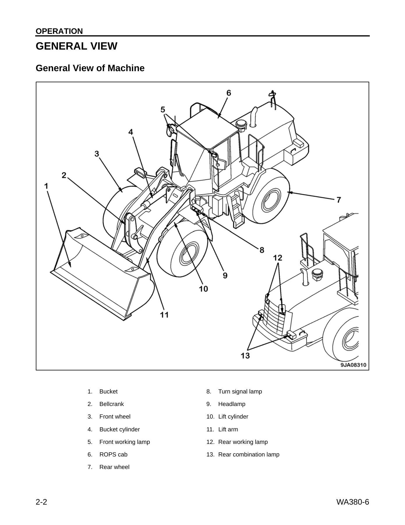
General View of Machinep. 72
Controls and Gaugesp. 73
Machine Monitorp. 74
Switch Panelp. 76
EXPLANATION OF COMPONENTSp. 77
Machine Monitorp. 77
Types of Warningsp. 78
Emergency Stopp. 78
Cautionp. 78
Mistaken Operationp. 78
Inspection and Maintenancep. 78
Central Warning Lampp. 78
Character Display Portionp. 79
Service Meterp. 80
Action Code Displayp. 80
Failure Code Displayp. 81
Filter, Oil Replacement Time Displayp. 82
Emergency Stop Itemsp. 84
Brake Oil Pressure Caution Lampp. 85
Engine Oil Pressure Caution Lampp. 85
Battery Charge Circuit Caution Lampp. 86
Steering Oil Pressure Caution Lamp (Red)p. 86
Caution Itemsp. 87
Brake Oil Temperature Caution Lampp. 88
Torque Converter Oil Temperature Caution Lampp. 88
Engine Coolant Temperature Caution Lampp. 89
Hydraulic Oil Temperature Caution Lampp. 89
Fuel Level Caution Lampp. 89
Inspection and Maintenance Itemsp. 90
Radiator Coolant Level Caution Lampp. 91
Engine Oil Level Caution Lampp. 91
Battery Electrolyte Level Caution Lampp. 91
Maintenance Caution Lampp. 92
Air Cleaner Clogging Caution Lampp. 92
Water Separator Caution Lampp. 92
Transmission Oil Filter Clogging Caution Lampp. 93
Pilot Display Portionp. 94
Parking Brake Pilot Lampp. 95
Cooling Fan Reverse Rotation Pilot Lampp. 95
Emergency Steering Pilot Lamp (Green)p. 95
Power Mode Pilot Lamp (P Mode)p. 96
Preheating Pilot Lampp. 96
Semi-Auto Digging Pilot Lampp. 96
Auto-Greasing Pilot Lampp. 96
Joystick Pilot Lampp. 96
Directional Selector Pilot Lampp. 97
Economy Operation Display Lampp. 97
Shift Indicatorp. 97
Auto-Shift Pilot Lampp. 97
Torque Converter Lockup Pilot Lampp. 97
Shift Hold Pilot Lampp. 98
Shift Lever Position Pilot Lampp. 98
Turn Signal Pilot Lampp. 98
Head Lamp High Beam Pilot Lampp. 98
Meter Display Portionp. 99
Torque Converter Oil Temperature Gaugep. 100
Engine Coolant Temperature Gaugep. 100
Hydraulic Temperature Gaugep. 100
Fuel Gaugep. 101
Speedometerp. 101
Meter Display Pilot Lampp. 101
OTHER FUNCTIONS OF MACHINE MONITORp. 102
Overall Menup. 102
Displaying Odometerp. 104
Resetting Filter, Oil Replacement Timep. 104
Entering Telephone Numberp. 105
Selecting Languagep. 106
Adjusting Monitor Brightnessp. 107
Switching Travel Speed/Engine Speed Displayp. 109
Switching Travel Speed/Engine Speed Display/Non-Displayp. 110
Switchesp. 112
Starting Switchp. 114
Power Mode Selector Switchp. 114
Transmission Shift Mode Selector Switchp. 115
Transmission Cutoff Switchp. 115
Transmission Cutoff Set Switchp. 116
Lamp Switchp. 116
Turn Signal Leverp. 116
Dimmer Switchp. 117
Horn Buttonp. 117
Hazard Lamp Switchp. 117
Parking Brake Switchp. 118
Front Working Lamp Switchp. 118
Rear Working Lamp Switchp. 119
Machine Monitor Mode Selector Switch 1p. 119
Machine Monitor Mode Selector Switch 2p. 119
Kickdown Switchp. 120
Hold Switchp. 121
Front Wiper Switchp. 121
Rear Wiper Switchp. 121
Cigarette Lighterp. 122
Room Lamp Switchp. 122
Rear Heated-Wire Glass Switchp. 122
Electronic Controlled Suspension System Switch (ECSS)p. 123
Emergency Steering Switchp. 123
Cooling Fan Reverse Rotation Switchp. 124
Cooling Fan Auto-Reverse Rotation Switchp. 124
Torque Converter Lockup Switchp. 127
Control Levers, Pedalsp. 128
Gearshift Leverp. 129
Directional Leverp. 131
Gearshift Lever Stopperp. 131
Work Equipment Lock Leverp. 132
Bucket Control Leverp. 132
Lift Arm Control Leverp. 133
Brake Pedalsp. 134
Accelerator Pedalp. 134
SECURITY LOCKS AND SAFETY FEATURESp. 135
Steering Column Tilt Leverp. 135
Cap with Lockp. 136
Opening the Cap (for Fuel Tank Filler Port)p. 136
Locking the Capp. 136
Opening the Cap (for Hydraulic Tank Filler Port)p. 137
Locking the Capp. 137
Backup Alarmp. 137
Frame Lock Barp. 138
Towing Pinp. 138
MACHINE FEATURESp. 139
Cab Doorp. 139
Emergency Escape Right Doorp. 139
Left Cab Door, Opening Lockp. 141
Left Cab Door, Door Handlep. 142
Left Cab Door, Door Open Knobp. 142
Cab Sliding Window Lock Release Knobp. 142
Cab Wiperp. 143
Grease Pumpp. 143
ELECTRICALp. 144
Fusesp. 144
Fuse Capacity and Circuitsp. 144
Slow-Blow Fusesp. 145
Power Outletp. 146
WORK OPERATIONSp. 147
Walk-Around Checkp. 147
Precautions Before Starting Work Operationsp. 147
Check Before Starting Enginep. 150
Check Machine Monitorp. 150
Check Coolant Level, Add Coolantp. 151
Check Oil Level in Engine Oil Pan, Add Oilp. 152
Check Water Separatorp. 153
Check Air Cleanerp. 155
Check Fuel Level, Add Fuelp. 156
Check Electric Wiringp. 157
Check Inflation Pressure of Tiresp. 157
Check Parking Brakep. 157
Check Brake Pedalp. 157
Check Condition of Window Washer Sprayp. 157
Check Wiping Efficiency of Wiperp. 158
Check Hornp. 158
Check Defroster Functionp. 158
Check Locksp. 158
Check Emergency Exitp. 158
Adjust Seatp. 159
Removal and Installation of Headrestp. 161
Adjust Seat Beltp. 162
Adjust Lever Standp. 163
Adjust Mirrorsp. 164
Final Checks Before Starting Enginep. 165
Starting Enginep. 167
Normal Startingp. 167
Starting Engine in Cold Weatherp. 169
Automatic Warming-Up Operationp. 170
Operations and Checks After Starting Enginep. 171
Breaking in the Machinep. 171
Checks After Starting Enginep. 171
Normal Operationp. 172
Stopping Enginep. 174
Check After Stopping Enginep. 174
Moving the Machine (Directional, Speed), Stopping the Machinep. 175
Moving the Machinep. 175
Changing Gear Speedp. 178
Changing Directionp. 179
Stopping the Machinep. 181
Adjusting Transmission Cutoff Positionp. 183
Turningp. 184
Emergency Steering (if equipped)p. 185
Operation of Work Equipmentp. 187
Lift Arm Operationp. 187
Bucket Operationp. 188
Work Possible Using Wheel Loaderp. 189
Digging Operationsp. 189
Loading Piled Soil or Blasted Rockp. 189
Digging and Loading on Level Groundp. 191
Leveling Operationsp. 192
Pushing Operationsp. 192
Load-and-Carry Operationsp. 192
Loading Operationsp. 193
Cross-Drive Loadingp. 193
V-Shape Loadingp. 193
Preparations for Loading, Gathering Rocksp. 194
Approaching Facingp. 194
Diggingp. 195
Traveling in Reverse After Excavationp. 197
Approaching Dump Truckp. 198
Loading Dump Truckp. 199
Reversing Away From Dump Truckp. 200
Precautionsp. 201
When Piling Up Loadsp. 201
When Handling Blasted Rockp. 201
During Cutting Face Operationsp. 205
When Switching Between Forward and Reversep. 205
When Turning When Tires Are Stationaryp. 205
Permissible Water Depthp. 206
When Wheel Brake Does Not Workp. 206
When Driving Up or Down Slopesp. 206
When Driving the Machinep. 207
Adjusting Work Equipmentp. 208
Adjusting Boom Kickoutp. 208
Adjusting Bucket Positionerp. 209
Bucket Level Indicatorp. 209
Measuring Dump Anglep. 210
Measuring Bucket Dump Anglep. 210
Measuring Coupler Dump Anglep. 213
Removing the Bucketp. 216
Installing the Bucketp. 217
Parking the Machinep. 219
Checks After Completion of Operationp. 221
Before Stopping Enginep. 221
After Stopping Enginep. 221
Locking the Machinep. 222
HANDLING TIRESp. 223
Precautions When Handling Tiresp. 223
Tire Pressurep. 224
Precautions for Using Load-and-Carry Methodp. 225
Precautions when Storing Tiresp. 225
TRANSPORTATIONp. 226
Transportation Procedurep. 226
Loading and Unloading Trailersp. 226
Loading Machinep. 226
Securing Machinep. 227
Unloading Machinep. 229
LIFTING MACHINEp. 230
Lifting Position Marksp. 230
Lifting Procedurep. 231
COLD WEATHER OPERATIONp. 232
Precautions for Low Temperaturep. 232
Fuel and Lubricantsp. 232
Coolantp. 232
Batteryp. 232
Precautions After Completion of Workp. 233
When Cold Weather Endsp. 233
LONG-TERM STORAGEp. 234
Before Storagep. 234
During Storagep. 234
After Storagep. 235
TROUBLESHOOTINGp. 236
When Machine Runs Out of Fuelp. 236
Towing the Machinep. 236
When Engine Can Be Usedp. 237
When Engine Cannot Be Usedp. 237
Releasing Parking Brakep. 238
Emergency Travel Operationp. 240
If Battery is Dischargedp. 241
Precautionsp. 241
Removing the Batteryp. 241
Installing the Batteryp. 241
Precautions for Charging Batteryp. 242
Starting Engine With Booster Cablep. 243
Precautions When Connecting or Disconnecting Booster Cablep. 243
Connecting Booster Cablep. 243
Starting Enginep. 244
Disconnecting Booster Cablep. 244
Other Troubleshootingp. 245
Electrical Systemp. 245
Chassisp. 246
Enginep. 248
MAINTENANCEp. 251
GUIDES TO MAINTENANCEp. 252
Check Service Meterp. 252
Komatsu Genuine Replacement Partsp. 252
Komatsu Genuine Oilsp. 252
Always Use Clean Washer Fluidp. 252
Always Use Clean Oil and Greasep. 252
Checking for Foreign Materials in Drained Oil and On Filtersp. 252
Fuel Strainerp. 252
Welding Instructionsp. 253
Do Not Drop Things Inside Machinep. 253
Dusty Work Sitesp. 253
Avoid Mixing Oilp. 253
Locking Inspection Coversp. 253
Bleeding Air from Hydraulic Circuitp. 254
Precautions When Installing Hydraulic Hosesp. 254
Checks After Inspection and Maintenancep. 254
OUTLINES OF SERVICEp. 255
Handling Oil, Fuel, Coolant, and Performing Oil Clinicp. 255
Oilp. 255
Fuelp. 256
Coolant and Water for Dilutionp. 256
Greasep. 257
Performing KOWA (Komatsu Oil Wear Analysis)p. 258
KOWA Analysis Itemsp. 258
Oil Samplingp. 258
Storing Oil and Fuelp. 259
Filtersp. 259
Outline of Electric Systemp. 259
WEAR PARTSp. 260
Wear Parts Listp. 260
RECOMMENDED FUEL, COOLANT, AND LUBRICANTSp. 261
Fuel, Coolant, and Lubricant Ambient Temperature Chartp. 262
Recommended Brands, Other Than Komatsu Genuine Oilp. 263
Biodiesel Usagep. 264
Biodiesel Recommendation for Komatsu Enginesp. 264
Biodiesel Terminologyp. 264
Certification and Standardsp. 265
Warranty and Use of Biodiesel Fuel in Komatsu Enginesp. 265
Requirements for Using Biodiesel Fuel in Komatsu Enginesp. 265
Properties of Biodieselp. 266
Komatsu Biodiesel Blend Specification for B5 to B20p. 267
Summary of Recommendationsp. 268
STANDARD TIGHTENING TORQUES FOR BOLTS AND NUTSp. 269
PERIODIC REPLACEMENT OF SAFETY-CRITICAL PARTSp. 271
MAINTENANCE SCHEDULE CHARTp. 273
SERVICE PROCEDUREp. 275
Initial 250 Hours Servicep. 275
Initial 1000 Hours Servicep. 275
When Requiredp. 276
Clean, Replace Air Cleaner Elementp. 276
Clean Inside of Cooling Systemp. 279
Check Transmission Oil Level, Add Oilp. 283
Check Axle Oil Level, Add Oilp. 284
Clean Axle Case Breatherp. 285
Clean Air Conditioner Condenserp. 286
Check Window Washer Fluid Level, Add Fluidp. 286
Clean Radiator Fins and Oil Cooler Finsp. 287
Turn, Replace Bolt-On Cutting Edgep. 290
Replace Bucket Teethp. 291
Check Air Conditionerp. 292
Replace Slow-Blow Fusep. 294
Check Accumulator Functionp. 295
Select Tiresp. 296
Check Tire Pressurep. 297
Check Before Startingp. 298
Every 50 Hours Servicep. 299
Drain Water, Sediment from Fuel Tankp. 299
Every 100 Hours Servicep. 299
Lubricate Rear Axle Pivot Pinp. 299
Clean Element in Air Conditioner Fresh Air Filterp. 300
Check Oil Level in Hydraulic Tank, Add Oilp. 301
Every 250 Hours Servicep. 302
Check Battery Electrolyte Levelp. 302
Check Parking Brakep. 304
Check Air Conditioner Compressor Belt Tension, Adjustp. 304
Check for Loose Wheel Hub Nuts, Tightenp. 305
Clean Element in Air Conditioner Recirculation Filterp. 305
Check Accumulator Functionp. 306
Lubricatingp. 307
Every 500 Hours Servicep. 308
Change Oil in Engine Oil Pan, Replace Engine Oil Filter Cartridgep. 308
Replace Fuel Prefilter Cartridgep. 310
Bleeding Air from Fuel Linep. 312
Every 1000 Hours Servicep. 313
Replace Fuel Main Filter Cartridgep. 313
Change Oil in Transmission Case, Change Transmission Oil Filter Cartridge, Clean Strainerp. 315
Clean Transmission Case Breatherp. 317
Lubricatingp. 317
Check Engine Air Intake Piping Clamps for Loosenessp. 317
Check Alternator Driving Belt Tension, Replacep. 318
Replace Corrosion Resistor Cartridgep. 318
Every 2000 Hours Servicep. 319
Change Oil in Hydraulic Tank, Replace Hydraulic Tank Filter Elementp. 319
Replace Hydraulic Tank Breather Elementp. 322
Change Axle Oilp. 323
Replace Element in Air Conditioner Recirculation Air Filter, Fresh Air Filterp. 323
Check Brake Disc Wearp. 324
Check Accumulator Functionp. 325
Check Alternatorp. 325
Check Engine Valve Clearance, Adjustp. 325
Check Vibration Damperp. 325
Every 4000 Hours Servicep. 326
Lubricatingp. 326
Check Water Pumpp. 327
Check Starting Motorp. 327
Check Air Conditioner Compressor, Adjustp. 327
Check for Loose Engine High-Pressure Piping Clamps, Hardening of Rubberp. 328
Check for Missing Fuel Spray Prevention Caps, Hardening of Rubberp. 329
Every 8000 Hours Servicep. 330
Replace High-Pressure Piping Clampsp. 330
Replace Fuel Spray Prevention Capsp. 330
SPECIFICATIONSp. 331
SPECIFICATIONSp. 332
OPTIONS, ATTACHMENTSp. 335
BUCKET AND TIRESp. 336
TORQUE CONVERTER LOCKUPp. 337
Componentsp. 337
Torque Converter Lockup Switchp. 338
Torque Converter Lockup Pilot Lampp. 338
Shift Indicatorp. 338
Character Displayp. 338
Method of Operationp. 339
Travel Speed Functionsp. 340
Travel Speed Warning Functionp. 340
Travel Speed Limit Functionp. 340
JOYSTICK STEERING SYSTEMp. 341
Structure and Functionp. 341
Componentsp. 342
Shift UP, Shift DOWN Switchesp. 343
Directional Selector Switchp. 343
Joystick Steering Leverp. 343
Joystick ON/OFF Switchp. 343
HI/LOW Selector Switchp. 344
Horn Switchp. 344
Console Tilt Leverp. 344
Console Fore-and-Aft Adjustment Leverp. 344
Joystick Pilot Lampp. 345
Armrest Adjustment Leverp. 345
Steering with Joystick Lever or Steering Wheelp. 346
Precautions for Steering with Joystickp. 347
Operating the Joystick Steering Systemp. 348
Getting In and Out of Operator’s Cabp. 351
Adjustmentsp. 352
Adjusting Joystick Consolep. 352
Adjusting Seatp. 353
AM/FM RADIO CASSETTE STEREO SOUND SYSTEMp. 356
Sound System Componentsp. 358
Power Switch/Volumep. 358
Auto-Store/Preset Scan Buttonp. 358
Bass Control Knobp. 358
Treble Control Knobp. 359
Loudness Buttonp. 359
Time/Radio Display Selector Buttonp. 359
Tape Eject Buttonp. 360
Cassette Doorp. 360
Fast-Forward, Rewind Buttonsp. 360
Preset Buttonsp. 360
Metal Tape Buttonp. 361
Manual Tuning Buttonsp. 361
Seek Tuning Buttonsp. 361
Band Selector Buttonp. 361
Method of Operationp. 362
Setting Preset Buttonsp. 362
Using Auto-Presetp. 362
Using Manual Presetp. 362
Listening to Radiop. 363
Listening to Cassette Tapep. 363
Reversing the Tapep. 364
Precautions When Usingp. 364
Handling Cassette Tapep. 364
AUTOMATIC AIR CONDITIONERp. 365
Control Panelp. 365
Main Power Switchp. 366
Fan Switchp. 366
Air Conditioner Switchp. 367
Auto Switchp. 368
Temperature Switchp. 368
FRESH/RECIRC Selector Switchp. 368
Mode Selector Switchp. 369
Method of Operationp. 370
Cooling Operationp. 370
Heating Operationp. 370
Drying-Heating and Demisting Operationp. 371
When Not Using the Air Conditioner Regularlyp. 371
Precautions When Using Air Conditionerp. 371
Inspection and Maintenancep. 372
Cool Boxp. 372
Multi-Function Leverp. 373
Componentsp. 373
Work Equipment Leverp. 374
Kickdown Switchp. 374
Hold Switchp. 375
FNR Switchp. 375
Directional Selector Switch Actuation Switchp. 376
Directional Selector Pilot Lampp. 376
Work Equipment Lock Switchp. 376
Using FNR Switch to Change Between Forward and Reversep. 377
MACHINES EQUIPPED WITH KOMTRAXp. 379
Basic Precautionsp. 379

Service and Repair Coverage in Detail

On the maintenance side the manual lays out the service schedule chart and then the individual procedures behind it. When-required work includes cleaning and replacing the air cleaner element, cleaning the cooling system, checking transmission and axle oil levels, cleaning the axle case breather and the air conditioner condenser, cleaning radiator and oil cooler fins, turning or replacing bolt-on cutting edges, replacing bucket teeth, checking the air conditioner, replacing slow-blow fuses, checking accumulator function, selecting tires and checking tire pressure. The 50, 100 and 250 hour services cover draining water and sediment from the fuel tank, lubricating the rear axle pivot pin, cleaning the air conditioner filters, checking the hydraulic tank oil level, checking battery electrolyte, checking the parking brake and air conditioner compressor belt tension, checking wheel hub nuts and greasing the machine. At 500 hours the engine oil and engine oil filter cartridge are changed and the fuel prefilter cartridge is replaced, followed by bleeding air from the fuel line. The 1000 hour service adds the fuel main filter cartridge, transmission oil and transmission oil filter cartridge with strainer cleaning, the transmission case breather, lubricating points, air intake piping clamps, alternator belt tension and the corrosion resistor cartridge.

At 2000 hours the hydraulic tank oil and filter element are changed along with the hydraulic tank breather element, the axle oil, the air conditioner recirculation and fresh air filter elements, and brake disc wear, accumulator function, alternator, engine valve clearance and vibration damper are checked. The 4000 hour service covers drive shaft and spline greasing, water pump, starting motor and air conditioner compressor checks, plus the engine high-pressure piping clamps and fuel spray prevention caps. At 8000 hours the high-pressure piping clamps and fuel spray prevention caps are replaced. Standard tightening torques for metric bolts and nuts from 6 mm through 39 mm thread diameter, together with the taper seal torque table for hydraulic hoses, are printed in full so fasteners can be brought back to specification instead of guessed at.

Specifications and Capacities You Can Work From

The specification section documents the WA380-6 with 23.5R25A L3 tires: machine weight, normal load, heaped bucket capacity, the Komatsu SAA6D107E-1 engine and its flywheel horsepower rating, overall length, height, width, bucket width, ground clearance, reach, dump angle, minimum turning radius and forward and reverse travel speeds for all four ranges. Fluid capacities for the engine oil pan, transmission case, hydraulic system, axles, fuel tank and cooling system are given in both liters and US gallons as specified and refill amounts, so a service can be planned without looking anything up elsewhere. The recommended fuel, coolant and lubricant chart ties the correct oil grade to the ambient temperature range the machine is working in, and the biodiesel section explains the B5 to B20 requirements, storage limits and the shortened filter intervals that apply when biodiesel blends are used.

Safety Information That Applies on the Job

The safety portion is not a formality. It reproduces the warning decals fitted to the machine and explains what each one is telling the operator β€” crush hazards in the articulated area, the safe distances to keep from low, high and special high voltage cables, the frame lock bar requirement for transport and hoisting, the parking brake emergency release, hot coolant and hot oil warnings, battery and booster cable handling, ROPS certification and the rule against modifying the structure. Travel rules cover the safe bucket height, working on slopes, what to do if the engine stops on a slope, braking capacity limits for loaded and unloaded machines, permissible water depth and the precautions for reversing with the rear blind spot. The maintenance safety rules set out warning tags, stopping the machine during maintenance, working under the machine, using compressed air, handling high-pressure hoses and fluids, and the correct way to inflate a tire in a protective cage.

Troubleshooting and Diagnostic Support

When something goes wrong, the manual provides a troubleshooting section split into electrical system, chassis and engine. Electrical entries cover lamps that glow dimly or flicker, a battery charge circuit caution lamp that stays on, alternator noise, a starting motor that will not turn or turns sluggishly or disengages early, and a preheating pilot lamp that does not illuminate. Chassis entries cover the transmission, axles, brakes, steering, parking brake and hydraulic system β€” for example a machine that will not move, low power, overheating oil, brake drag, heavy steering, weak bucket lifting or irregular cylinder movement. Engine entries cover low oil pressure, overheating with steam from the radiator, hard starting, white or blue exhaust, intermittent black exhaust, combustion noise and abnormal mechanical noise. Each entry lists the likely causes and the remedy, and where a repair needs dealer-level attention the manual says so plainly.

Options and Attachment Documentation

Because many WA380-6 machines were delivered with factory or field options, the manual documents the ones that change how the machine is operated. The torque converter lockup section covers the switch, the lockup pilot lamp, the speed ranges and travel speeds at which lockup engages and cancels, the travel speed warning and limit functions, and the overrun protection that stops a downshift that would overspeed the engine. The joystick steering system section explains the joystick lever, ON/OFF switch, HI/LOW selector, directional selector switch, shift UP and DOWN switches, horn switch, console tilt and fore-and-aft adjustment levers, how to steer with the joystick, how it differs from the steering wheel, and the neutral interlock behaviour. The multi-function lever section covers the work equipment lever, kickdown switch, hold switch, FNR switch and directional selector pilot lamp. The automatic air conditioner section covers the control panel, cooling, heating, drying-heating and demisting operation, and the inspection and maintenance intervals for the filters, condenser, belt, refrigerant, piping and receiver drier.

Who This Manual Is For

This Komatsu WA380-6 Wheel Loader Operation and Maintenance Manual suits owner-operators who want to run the loader correctly and keep up the daily and periodic checks themselves, fleet maintenance staff building a service schedule around the machine’s operating hours, and technicians who need the correct capacities, torques, wear limits and replacement procedures in front of them rather than from memory. It is equally useful for a new operator learning the machine monitor, the work equipment controls and the safe travel rules, and for an experienced hand who needs the exact action code meaning or the correct filter interval. The troubleshooting chapters help narrow down a fault before parts are ordered, and the safety-critical parts list gives the replacement intervals that keep the machine compliant and safe over its working life.

What You Can Do With It

With this manual in hand you can read and act on machine monitor warnings, carry out the full daily and periodic service schedule, change the engine oil and filters, replace the fuel prefilter and main filter cartridges, change transmission and hydraulic oil with the correct strainer and filter service, change axle oil, adjust the transmission cutoff position, check and adjust the air conditioner compressor belt, inspect brake disc wear, check accumulator function, remove and install the bucket, adjust the boom kickout and bucket positioner, measure the dump angle and handle the machine correctly on slopes, in cold weather and during transport. Having the correct procedures and the correct specification values in one document is what separates a machine that lasts from one that is nursed from one failure to the next. Every value in the tables β€” the tightening torques, the capacities, the wear limits, the pressure and temperature ranges β€” is there so a repair can be done once and done right.

IMAGES PREVIEW

Komatsu WA380-6 Wheel Loader Operation and Maintenance Manual - PDF β€” PDF page 26 preview
Komatsu WA380-6 Wheel Loader Operation and Maintenance Manual - PDF β€” PDF page 72 preview
Komatsu WA380-6 Wheel Loader Operation and Maintenance Manual - PDF β€” PDF page 8 preview

The manual is delivered as an instant PDF download after payment, so there is no shipping and no waiting. Keep it on a phone, tablet or laptop in the cab or the workshop, print the pages you need for a job, and work from the same document wherever the machine is. For a WA380-6 owner or technician, this is the working reference for the whole machine.
Reviews

There are no reviews yet.

Be the first to review “Komatsu WA380-6 Wheel Loader Operation and Maintenance Manual – PDF”

What Our Customers Say

β˜…β˜…β˜…β˜…β˜… Live reviews from customers
Loading customer reviews...
0
    0
    Your Cart
    Your cart is emptyReturn to Shop
    πŸ›’
    Recently Purchased
    πŸ•’ verified order