
Komatsu WA430-5 Wheel Loader Shop Manual – 1166 Page Complete Service & Repair Guide PDF
Original price was: $44.95.$27.95Current price is: $27.95.
Complete 1166-page Komatsu WA430-5 wheel loader shop manual covering engine, transmission, torque converter, axles, brakes, steering, hydraulics, electrical systems, testing and adjusting, disassembly and assembly, plus full troubleshooting charts for serial numbers 60001 and up.
Description
Komatsu WA430-5 Wheel Loader Shop Manual – The Complete Technical Reference
This is the full Komatsu shop manual for the WA430-5 wheel loader, covering machines from serial number 60001 and up. The manual is presented as a single 1166-page PDF and spans five top-level chapters that together form the complete service, repair, testing, adjustment, and troubleshooting reference for this machine. Whether you are rebuilding a transmission, diagnosing an electrical fault, adjusting hydraulic pressures, or carrying out a routine service, the relevant procedure, specification, and illustration are all contained inside this one document.
The manual applies to machines fitted with the SAA6D125E-3 engine. For details specific to that powerplant, Komatsu directs technicians to the 125 Series Engine Shop Manual; this volume carries everything around the engine – mounts, cooling, driveline, hydraulics, electrical, and controls.
File Details
- Manual type: Komatsu Shop Manual (Service / Repair)
- Brand: Komatsu
- Model: WA430-5 Wheel Loader
- Serial numbers: 60001 and up
- Engine: SAA6D125E-3
- Language: English
- Page count: 1166 pages
- File format: PDF
Chapters Covered
The manual follows the standard Komatsu shop manual structure and splits the machine into five top-level chapters:
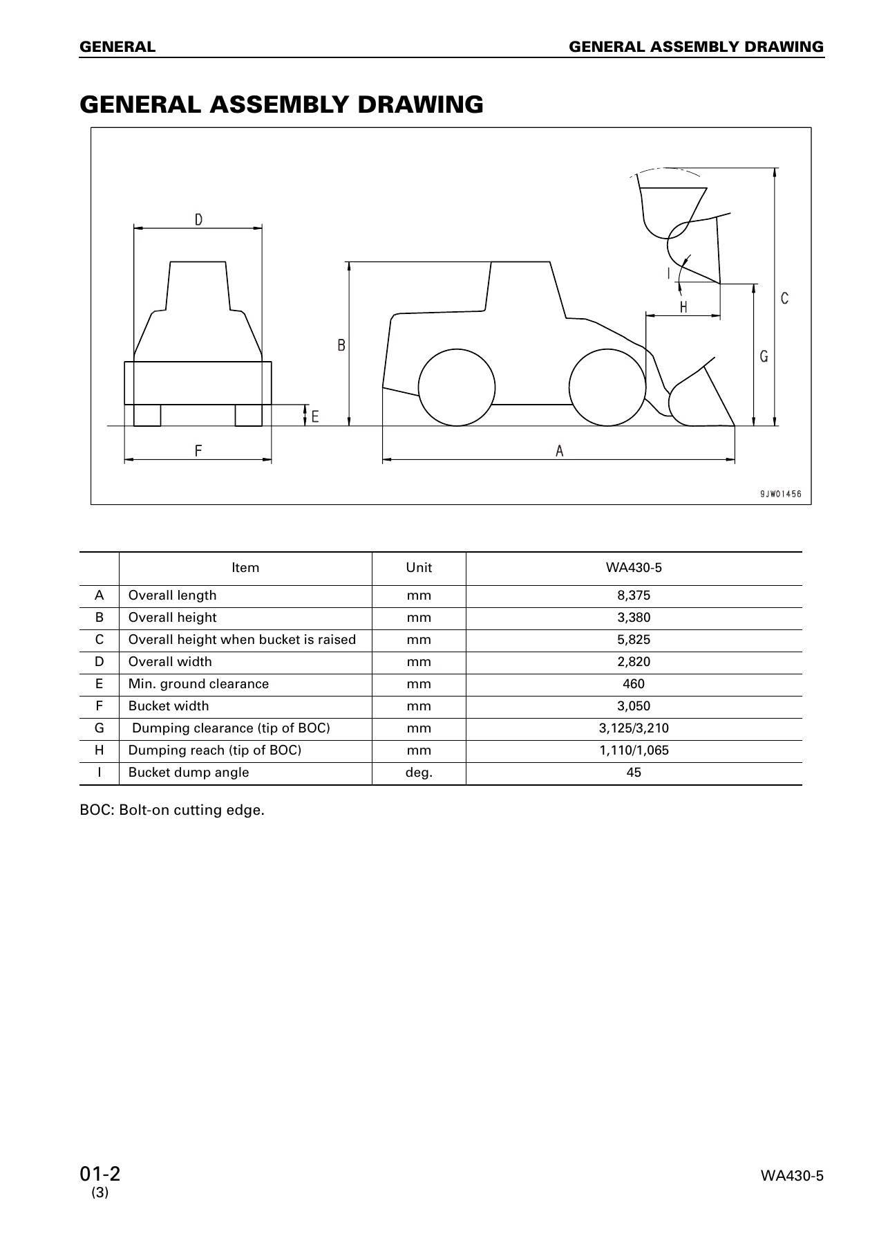
- 01 GENERAL – General assembly drawing, machine specifications, engine specifications, power train specifications, hydraulic system data, weight table, and the lubricant and coolant chart.
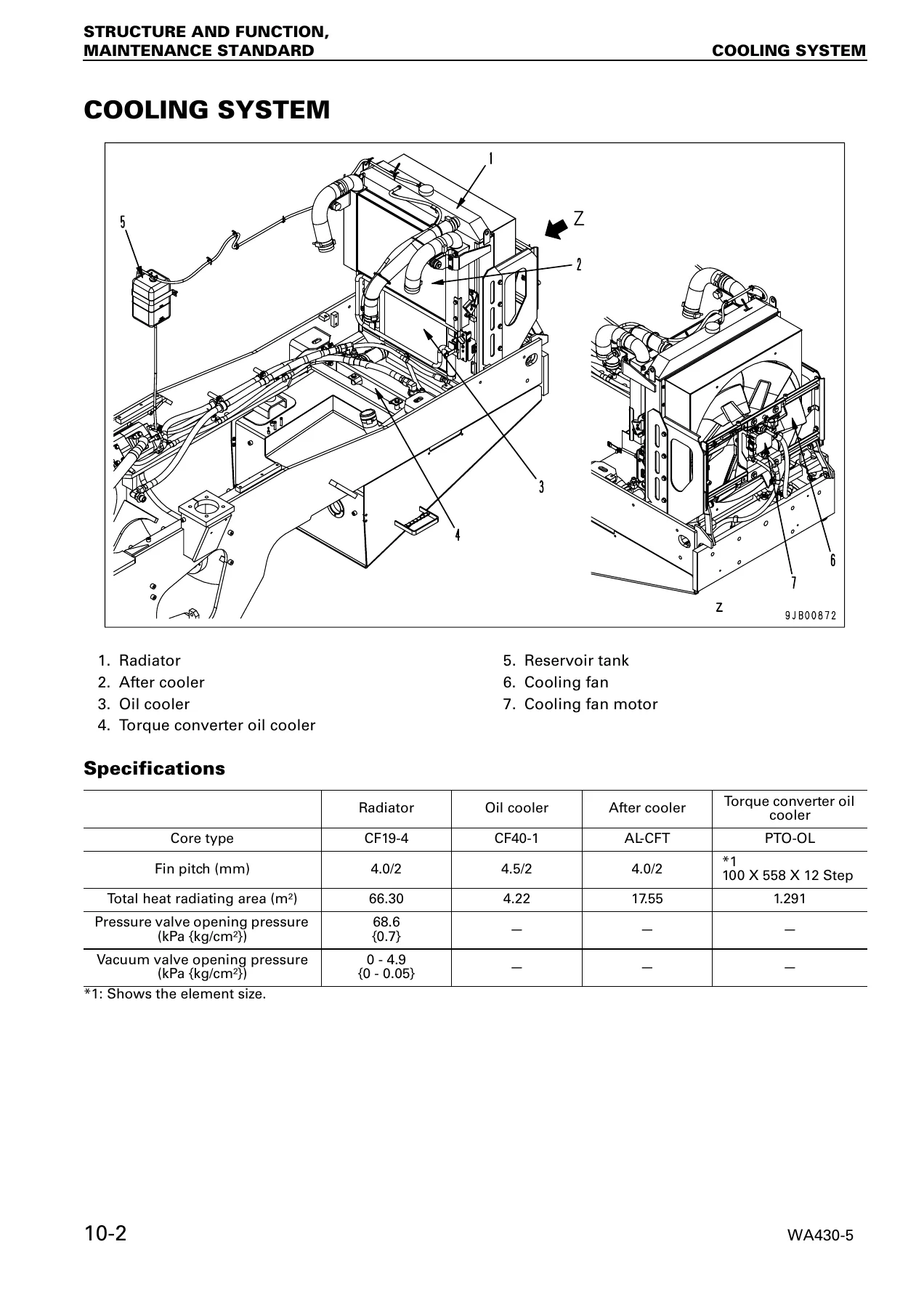
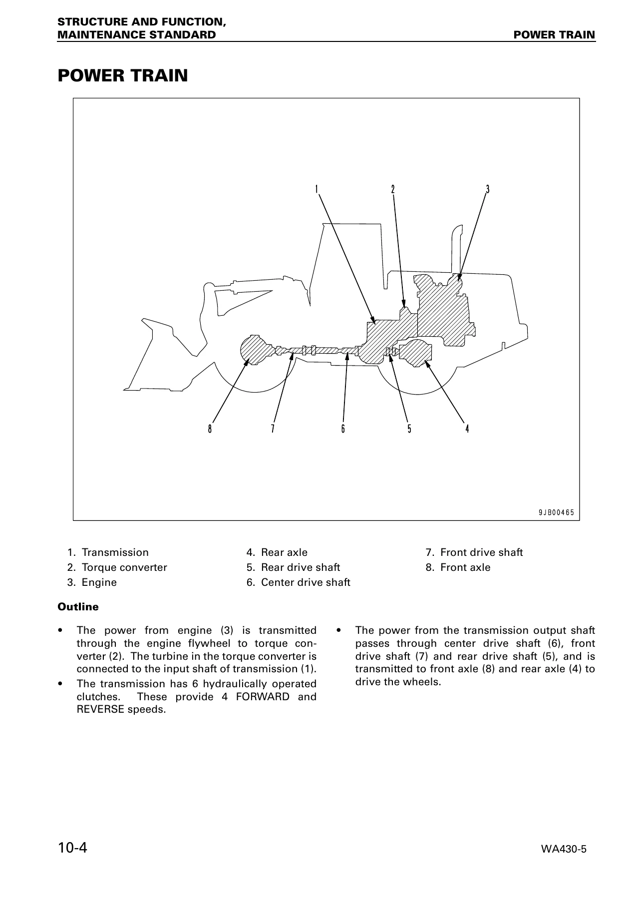
- 10 STRUCTURE, FUNCTION AND MAINTENANCE STANDARD – Cooling system, engine and transmission mounts, power train, torque converter, transmission and transmission control valve, axles, differential, final drive, center hinge pin, steering system (column, orbit-roll, steering valve, demand valve, pumps, cylinders), brake piping and valves, accumulator, wheel and parking brakes, hydraulic tank and piping, work equipment control valve, PPC valves, EPC solenoid valve, cooling fan motor and drive pump, work equipment linkage and bucket, cylinders, cab, air conditioner, machine monitoring system, and the transmission and work equipment control systems.
- 20 TESTING AND ADJUSTING – Testing and adjusting data, chassis standard value tables, engine testing (speed, exhaust color and temperature, valve clearance, compression pressure, blow-by, oil pressure, boost pressure, fuel injection timing), transmission and torque converter power train oil pressure testing, steering testing and adjustment, hydraulic fan testing, brake oil pressure, accumulator charge pressure, work equipment PPC and hydraulic pressure, bucket positioner, lift arm kick-out, machine monitor adjustment, load meter testing, bleeding procedures, and releasing residual pressures.
- 30 DISASSEMBLY AND ASSEMBLY – Removal and installation procedures for fuel injection pump, nozzle holders, cylinder head, engine assembly, after cooler, cooling fan motor, radiator and fan motor assembly, fuel tank, parking brake disc and plate, torque converter and transmission assembly, front and rear axle assemblies, center hinge pin, cab assembly, cab and floor frame, operator’s cab glass, pump assemblies, steering demand valve, travel damper valve, work equipment valve, hydraulic tank, hydraulic cylinders, counterweight, air conditioner unit and compressor, and operator’s seat. Includes full disassembly and assembly of the transmission, clutch packs, parking brake, torque converter (standard and lock-up), axle housing, and differential.
- 90 OTHERS – Power train oil circuit diagrams (with and without torque converter lock-up clutch), full hydraulic circuit diagram, and complete electrical circuit diagrams.
Under each chapter the manual organises information by component system, and much of the testing, disassembly, and assembly content is supported by photographed procedures and illustrated diagrams. The Troubleshooting sections alone run to hundreds of pages with flowcharts, failure code tables, and diagnostic procedures for the transmission control system, work equipment control system, monitor panel system, hydraulic and mechanical systems, and electrical system.
Troubleshooting Coverage in Detail
One of the strongest parts of this shop manual is the troubleshooting material. It is organised into distinct diagnostic modes so a technician can move directly to the relevant chart:
- TM mode – Transmission control system, including failure codes for ECMV solenoids, fill switches, speed sensors, relay outputs, and shifting faults.
- WRK mode – Work equipment control system, covering joystick, EPC, detent, and remote positioner faults.
- MON mode – Monitor panel system, sensor signals, switch inputs, communication faults, and warning lamp diagnostics.
- H mode – Hydraulic and mechanical failures, from a machine that will not start through to steering, brake, lift arm, and bucket faults.
- E mode – Electrical system faults, from engine starting and preheating through to wipers, lamps, horn, and air conditioning.
- S mode – Engine troubleshooting reference tables.
The troubleshooting section also includes a full failure code table with controller codes, problem code definitions, real-time monitoring item tables, and the procedure for reading input and output signals on the machine monitor. This makes it possible to diagnose faults systematically instead of replacing parts by guesswork.
Why the Komatsu WA430-5 Shop Manual Matters
The WA430-5 is a large articulated wheel loader, and the systems on it are integrated – the transmission, torque converter, hydraulic fan drive, steering, brakes, and work equipment all talk to each other through controllers and sensors. Servicing it without the correct procedure often means guessing at torque values, clearances, oil pressures, and diagnostic routines. This manual removes that guesswork. It gives the correct specifications for the engine, the power train, the hydraulic circuit, and the electrical circuit, and it explains the sequence in which components must be removed and installed.
When you are inside the transmission replacing a clutch pack, or setting the main relief valve pressure, or chasing a failure code on the monitor, this is the reference that tells you what the value should be, what the cause is likely to be, and what steps to take next. It also contains the standard tightening torque tables, the conversion tables, the electrical wire colour codes, and the connector pin-out tables needed to work accurately rather than approximately.
What You Can Do With This Komatsu WA430-5 Manual
- Diagnose and repair engine, transmission, torque converter, axle, brake, steering, and hydraulic faults using the manufacturer’s own troubleshooting flowcharts and failure code tables.
- Carry out testing and adjustment of engine speed, valve clearance, compression, boost pressure, power train oil pressure, steering pressure, brake pressure, accumulator charge pressure, PPC pressure, and work equipment relief pressure.
- Remove and install major assemblies including the engine, transmission, torque converter, axles, differential, final drive, cab, hydraulic tank, work equipment valve, and hydraulic cylinders.
- Disassemble and rebuild the transmission, clutch packs, parking brake, torque converter, axle housing, and differential to factory specification.
- Read and interpret the power train oil circuit, hydraulic circuit, and full electrical circuit diagrams.
- Identify correct lubrication and coolant requirements, capacities, and service intervals.
- Check and adjust bucket positioner, lift arm kick-out, proximity switches, and the load meter.
IMAGES PREVIEW
Instant PDF Delivery
This Komatsu WA430-5 shop manual is delivered as an instant download PDF – no shipping, no waiting. Once payment is complete you can open it on any device, print the pages you need for the workshop, and keep the complete reference on hand for every job. Whether you are a professional technician, a fleet maintenance planner, or an owner-operator keeping a WA430-5 in service, this manual is the single most useful document you can have for the machine.
Reviews
There are no reviews yet.