
Komatsu WA430-5 Wheel Loader Shop Manual – Full PDF Download
Original price was: $39.95.$23.95Current price is: $23.95.
Complete 1,166-page Komatsu WA430-5 wheel loader shop manual covering serial number 60001 and up, with structure and function, testing and adjusting, disassembly and assembly, hydraulic and electrical circuit diagrams.
Description
Komatsu WA430-5 Wheel Loader Shop Manual
This is the complete Komatsu WA430-5 shop manual for machines from serial number 60001 and up. The 1,166-page document covers the SAA6D125E-3 powered wheel loader from top to bottom: cooling, power train, torque converter, transmission, axles, differentials, brakes, steering, hydraulics, work equipment, cab electrics, monitoring system, controllers and sensors. Every major assembly on this machine has a dedicated section covering how it is built, how it is supposed to behave, how to test it and how to take it apart and put it back together correctly.
File Details
- Manual type: Shop Manual (Structure & Function, Maintenance Standard, Testing & Adjusting, Disassembly & Assembly)
- Brand: Komatsu
- Machine model: WA430-5 wheel loader
- Serial number coverage: 60001 and up
- Engine covered: SAA6D125E-3 (engine internal details are in the 125 Series Engine Shop Manual)
- Language: English
- Page count: 1,166 pages
- File format: PDF
- Document number: SEBM025405
Chapters Covered
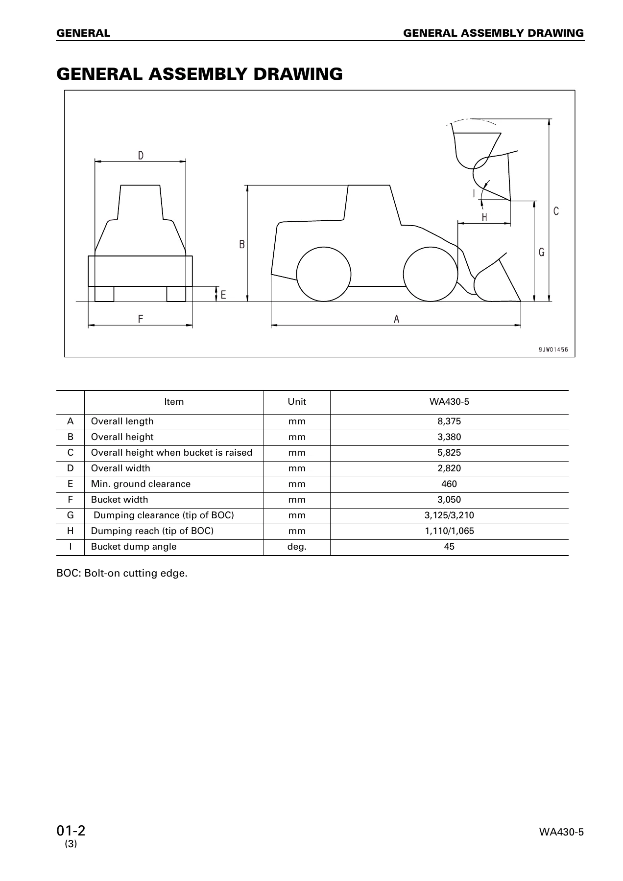
- 01 General – General assembly drawing, Specifications, Weight table, Lubricant and coolant list
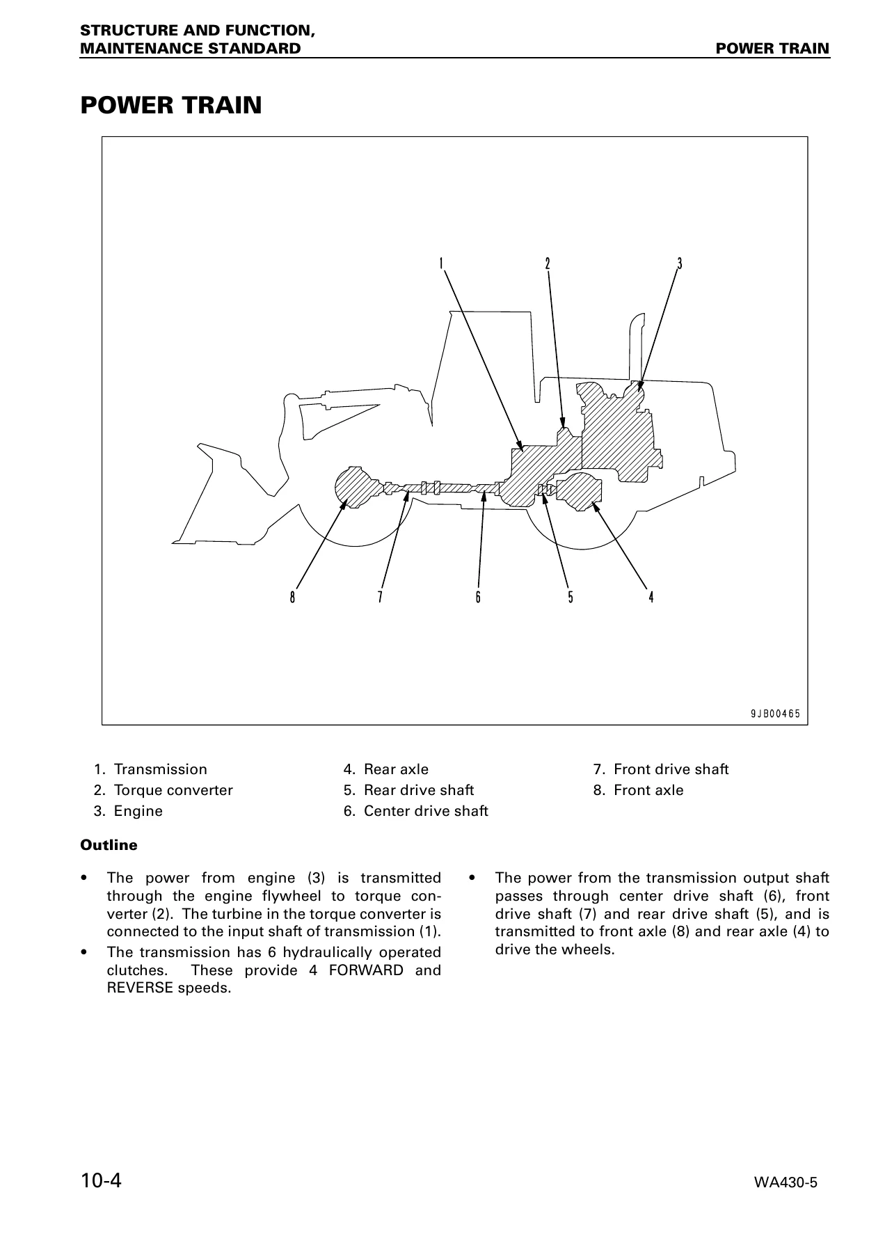
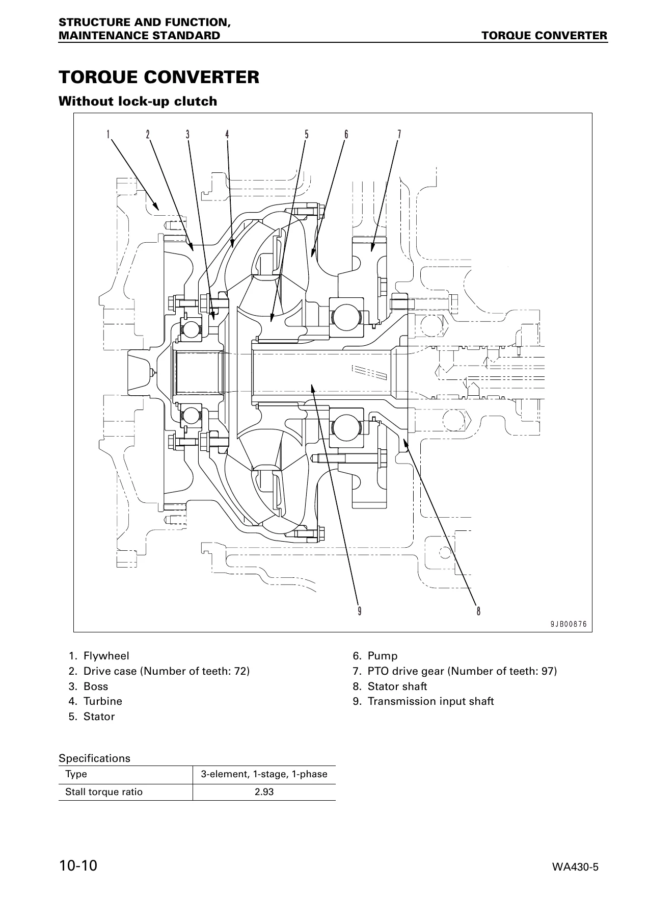
- 10 Structure, Function and Maintenance Standard – Cooling system, Engine and transmission mounts, Power train, Drive shafts, Torque converter and transmission piping, Torque converter, Transmission, Transmission control valve, Axle, Differential, Final drive, Axle mounting and center hinge pin, Steering piping, Steering column and orbit-roll, Steering valve, Orbit-roll valve, Stop valve, Steering pump and switch pump, Emergency steering pump and motor, Steering cylinder, Joystick steering lever, Steering switch valve, Brake piping, Brake valve, Charge valve, Accumulator, Brake, Parking brake and its control, Parking brake solenoid valve, Parking brake emergency release valve, Hydraulic piping, Work equipment control lever, Hydraulic tank, Torque converter charging, work equipment and pilot control pumps, PPC relief valve, E.C.S.S. valve, Work equipment control valve, Work equipment PPC valve, PPC valve, EPC solenoid valve, Shut off valve, Attachment PPC valve, Cooling fan motor and drive pump, Work equipment linkage, Bucket, Bucket positioner and lift arm kick-out, Work equipment cylinder, Cab, Air conditioner, Machine monitoring system, Machine monitor, Transmission control system, Transmission controller, Work equipment control system, Work equipment controller, Electric transmission control, Kick down and hold switch, Engine starting circuit, Engine stop circuit, Preheating circuit, Engine power mode selector circuit, Parking brake circuit, Sensors
- 20 Testing and Adjusting – Testing and adjusting data, Standard value table for chassis, Measuring engine speed, Measuring exhaust colour and temperature, Adjusting valve clearance, Measuring compression and blow-by pressure, Measuring engine oil pressure, Measuring intake air pressure, Testing and adjusting fuel injection timing, Adjusting engine speed sensor, Bleeding air from fuel circuit, Adjusting engine stop motor lever, Adjusting accelerator pedal, Adjusting transmission speed sensor, Testing and adjusting power train oil pressure, Flushing torque converter and transmission hydraulic circuit, Moving the machine when the transmission valve fails, Testing and adjusting steering control and steering oil pressure, Testing hydraulic fan, Measuring brake oil pressure, Testing wheel brake disc wear, Bleeding air from brake circuit, Testing parking brake disc wear, Manual release of parking brake, Testing and adjusting accumulator charge pressure, Testing and adjusting work equipment PPC and hydraulic pressure, Testing and adjusting bucket positioner and lift arm kick-out, Checking proximity switch pilot lamp, Adjusting machine monitor, Testing and adjusting load meter, Bleeding air, Releasing remaining pressure in hydraulic and travel damper circuits, PM clinic inspection chart, plus full Troubleshooting in TM, WRK, MON, H, E and engine S modes
- 30 Disassembly and Assembly – Fuel injection pump assembly, Nozzle holder assembly, Cylinder head assembly, Engine assembly, After cooler assembly, Cooling fan motor assembly, Radiator, fan motor and after cooler assembly, Fuel tank assembly, Parking brake disc and plate, Torque converter and transmission assembly, Transmission assembly, Transmission clutch pack assembly, Parking brake assembly, Torque converter assembly (standard and lock-up), Front axle assembly, Rear axle assembly, Axle housing assembly, Differential assembly, Center hinge pin, Cab assembly, Cab and floor frame assembly, Operator’s cab glass, Torque converter/work equipment/pilot control pump assembly, Steering/switch/fan pump assembly, Steering demand valve assembly, Travel damper valve assembly, Work equipment valve assembly, Hydraulic tank, Hydraulic cylinder, Counterweight, Air conditioner unit, Air conditioner compressor, and operator’s seat assembly
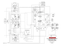
- 90 Others – Hydraulic circuit diagrams and electrical circuit diagrams
What ties the whole manual together is the maintenance standard data built into every chapter. Clearance limits, service limits, standard shim thicknesses, spring free lengths and installed loads, tightening torques, wear repair limits and remeasurement values are listed directly next to the components they apply to. For a machine like the WA430-5, that means a technician can measure a worn part, compare it against the printed limit and make a decision without pulling out a separate specification sheet.
What This Manual Enables You To Do
The scope is wide enough that a workshop can handle the WA430-5 from routine checks up to major component overhaul. On the powertrain side, the manual walks through the torque converter and transmission from the F and R clutch packs down to the control valve ECMV and fill switches, and it includes the transmission initial learning procedure that the controller needs after a rebuild or replacement. On the chassis side, the axle housing, differential, final drive and brakes are covered with disassembly and assembly procedures, shim selection, tooth contact inspection and bearing preload measurement. The hydraulic section handles the work equipment control valve, PPC and EPC valves, accumulators, charge valve, travel damper, steering demand valve and every hydraulic cylinder on the machine. The electrical content includes the machine monitoring system, the controllers on the network, connectors, pinout tables, real-time monitoring and the troubleshooting flowcharts that break a symptom down into tests with standard values.
The testing and adjusting chapter is effectively a diagnostic companion to the rest of the manual. It gives the standard and service limit values for engine speed, torque converter stall, hydraulic stall, main relief pressure, ECMV clutch pressures, steering relief pressure, brake oil pressure, accumulator cut-in and cut-out pressures, PPC output pressures, work equipment relief pressure, fan speed, and oil pressure drifts of the lift arm and bucket cylinders. When a complaint like slow lift, weak bucket tilt, dragging brake or hunting transmission comes in, the relevant measured value and the correct cause can be matched against the printed specification rather than guessed at.
Coverage Focus for the WA430-5
Because the manual is written for one machine — serial 60001 and up — rather than a family of loaders, the data is specific. Machine dimensions, bucket capacities, travel speeds, rimpull, tire sizes and inflation pressures are listed for this model. The engine is the SAA6D125E-3, and the manual notes that internal engine repair details sit in the separate 125 Series Engine Shop Manual, so this shop manual concentrates on how the engine is mounted, cooled, fuelled, governed and tied into the transmission and hydraulics. This keeps the document focused on the chassis, powertrain, hydraulic, electrical and control systems of the loader itself, which is exactly what a service technician usually needs in front of them.
Get the Manual
Whether you are diagnosing a fault, rebuilding a transmission, resealing an axle, calibrating the machine monitor after a controller swap, or simply confirming the correct torque before tightening a cylinder head, this Komatsu WA430-5 wheel loader shop manual puts the procedures, values and diagrams for the job in one searchable reference. It is the same technical content a Komatsu service workshop would work from, and it covers every major system on the machine in one document.
Delivery is instant. The PDF is available immediately after checkout, with no shipping and no waiting. It opens on a computer, tablet or phone, and any page can be printed for use on the shop floor so the original file stays clean. Keep it on a laptop in the workshop, on a tablet at the machine, or print the section you need for the job at hand.
IMAGES PREVIEW
Reviews
There are no reviews yet.