
Komatsu WA430-6 Wheel Loader Shop Manual – Troubleshooting by Failure Code PDF
Original price was: $52.95.$34.95Current price is: $34.95.
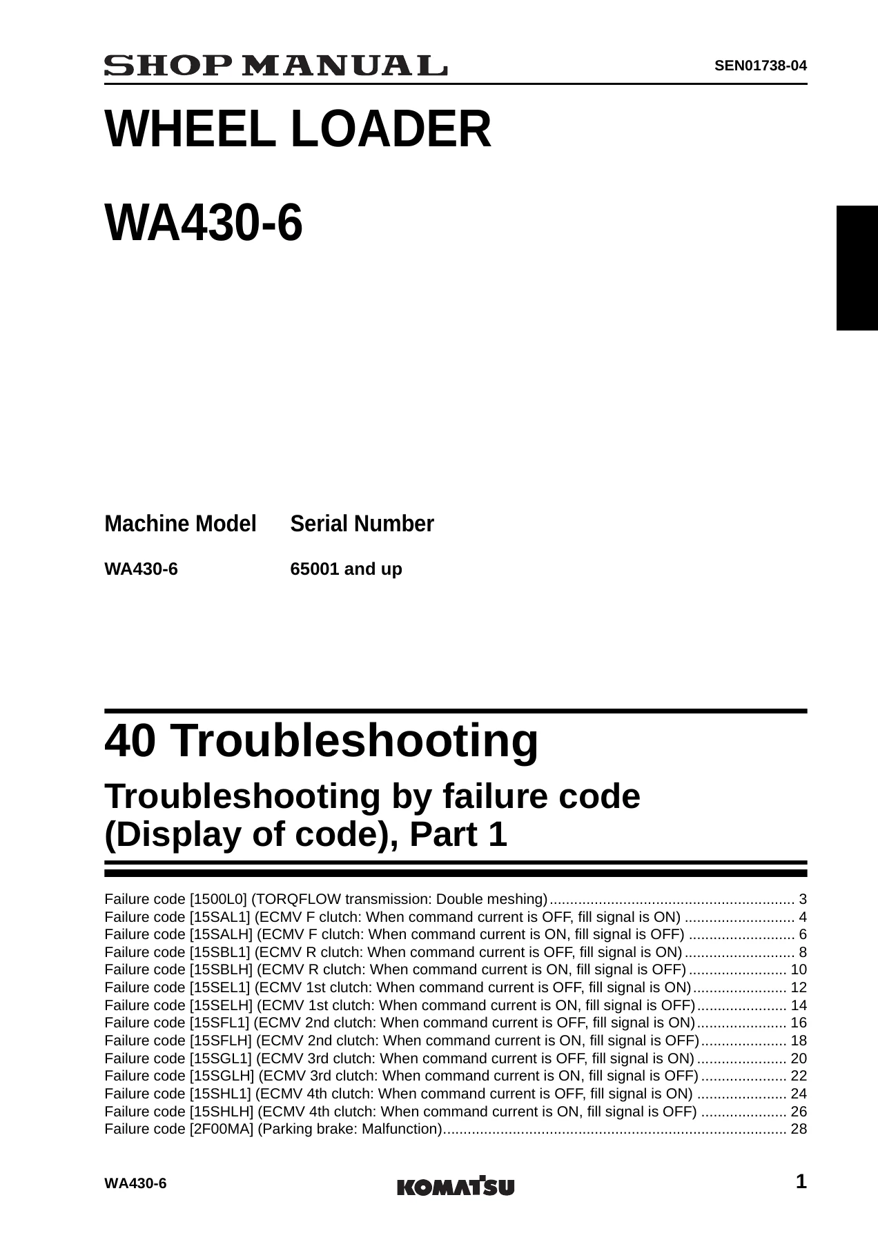
Complete Komatsu WA430-6 wheel loader shop manual covering troubleshooting by failure code across all controllers. 551 pages of diagnostic procedures, circuit diagrams, resistance and voltage specifications, and standard values for serial number 65001 and up.
Description
Komatsu WA430-6 Wheel Loader Shop Manual – Troubleshooting by Failure Code
This comprehensive shop manual covers the complete troubleshooting and failure code diagnostics for the Komatsu WA430-6 wheel loader, serial number 65001 and up. Spanning 551 pages across ten troubleshooting sections (Parts 1 through 10), this PDF gives technicians and owners the exact diagnostic procedures, circuit diagrams, resistance and voltage specifications, and component test values needed to identify and resolve faults across every major control system on the machine.
Whether you are chasing an intermittent transmission fault, diagnosing an engine sensor error, or tracing a CAN communication problem, this manual provides the failure code tables, possible causes, and standard values that Komatsu service technicians rely on. Every failure code entry includes the controller’s action, the problem that appears on the machine, related monitoring functions, and a step-by-step troubleshooting table with resistance and voltage specifications.
File Details
- Manual type: Shop Manual – Troubleshooting Sections
- Brand: Komatsu
- Model: WA430-6 Wheel Loader
- Serial number: 65001 and up
- Language: English
- Page count: 551
- File format: PDF
- Document numbers: SEN01738-04, SEN01739-04, SEN01740-05, SEN01741-02, SEN01742-03, SEN01743-03, SEN01744-02, SEN01745-02, SEN01746-01, SEN01747-02
Chapters Covered
- Troubleshooting by failure code (Display of code), Part 1 – Transmission and parking brake systems
- Troubleshooting by failure code (Display of code), Part 2 – Engine controller and machine monitor systems
- Troubleshooting by failure code (Display of code), Part 3 – Engine controller systems continued
- Troubleshooting by failure code (Display of code), Part 4 – Transmission controller, ECSS, and relay systems
- Troubleshooting by failure code (Display of code), Part 5 – Controller communication and switch diagnostics
- Troubleshooting by failure code (Display of code), Part 6 – FNR switches, steering pressure, and temperature sensors
- Troubleshooting by failure code (Display of code), Part 7 – Loader pump, lift arm, and EPC lever potentiometers
- Troubleshooting by failure code (Display of code), Part 8 – Joystick steering EPC, angle sensors, and solenoid valves
- Troubleshooting by failure code (Display of code), Part 9 – Solenoid valve and detent diagnostics
- Troubleshooting by failure code (Display of code), Part 10 – Clutch ECMV solenoids and emergency steering
Transmission and Directional Control Systems
The transmission troubleshooting sections cover every failure code related to the TORQFLOW transmission, including double meshing faults, clutch ECMV (Electronically Controlled Modulating Valve) solenoid diagnostics for the F (Forward), R (Reverse), 1st, 2nd, 3rd, and 4th clutches, and fill switch signal disagreements. Each failure code includes the controller’s response, the effect on machine operation, and a detailed troubleshooting table with resistance values for fill switches, wiring harness checks, and transmission controller pin voltages. The parking brake system failure codes are also covered, with procedures for testing the parking brake indicator switch and related circuits.
Engine Controller Diagnostics
Engine-related failure codes span multiple sections and cover charge pressure sensors, throttle sensors, coolant temperature sensors, charge temperature sensors, atmospheric pressure sensors, engine oil pressure switches, battery voltage errors, common rail pressure faults, injector circuit errors for all six cylinders, engine speed sensors (Ne and Bkup), and the KOMNET datalink. Each entry details the sensor’s normal operating range, resistance values at specified temperatures, voltage specifications for signal and power supply circuits, and the standard values used to determine whether a sensor, wiring harness, or the engine controller itself is at fault. The engine overspeed, derating, and water-in-fuel codes are also included with their specific diagnostic criteria.
Machine Monitor and Warning Systems
The machine monitor system failure codes cover air cleaner clogging, alternator signal and malfunction errors, engine oil level, coolant level, brake oil overheating, torque converter oil overheating, hydraulic oil overheating, and the various sensor input errors. Troubleshooting tables provide resistance specifications for the dust indicator relay, coolant level sensor, oil level sensors, and temperature sensors, along with voltage values for the machine monitor connector pins. The manual also includes procedures for checking the alarm buzzer circuit and machine monitor power supply errors.
Work Equipment Controller Systems
Work equipment failure codes cover the bucket positioner proximity switches, lift arm EPC lever potentiometers (Main and Sub), bucket EPC lever potentiometers, joystick steering EPC lever potentiometers, lift arm angle sensor, and the various EPC solenoids for lift arm raise/lower, bucket tilt/dump, and joystick steering right/left. Each potentiometer entry includes the resistance value at the specified measurement points, voltage output ranges for neutral, raise, lower, tilt, dump, and float positions, and the expected values at detent positions. Solenoid diagnostics cover disconnection, short circuit, and short circuit with power supply line conditions, with coil resistance values and voltage checks at the controller connector.
CAN Communication and Controller Diagnostics
The CAN communication troubleshooting sections cover the KOMNET datalink timeout error, CAN communication failures between the machine monitor and transmission controller, engine controller, and work equipment controller, as well as model selection and option setting disagreements. The manual provides CAN end point resistance values, wiring harness continuity checks for CAN H and CAN L circuits, and procedures for identifying which controller on the network is causing the communication fault. Controller power supply and ground circuit diagnostics are also included, with voltage specifications for the transmission controller, work equipment controller, and engine controller.
Switch and Sensor Failure Codes
Numerous switch-related failure codes are covered, including panel switches that remain pressed for extended periods (t, U, switches), load meter switches, fan reverse switches, remote positioner set switches, transmission cut-off set switch, kick-down switch, hold switch, and parking brake neutralizer switch. Temperature sensor diagnostics cover the transmission oil temperature sensor, hydraulic oil temperature sensor, rear brake oil temperature sensor, and torque converter oil temperature sensor, with resistance values at 25 degrees C and 100 degrees C and voltage output specifications.
Emergency Steering and Special Systems
The manual includes troubleshooting for the emergency steering relay, motor-driven emergency steering pump failures, emergency steering operation time alarms, joystick steering neutral safety relay, joystick steering solenoid cut relay, and ECSS solenoid diagnostics. Each failure code includes the relay coil resistance, contact continuity checks, voltage measurements at the relay connector, and procedures for identifying wiring harness faults versus component failures.
Circuit Diagrams Throughout
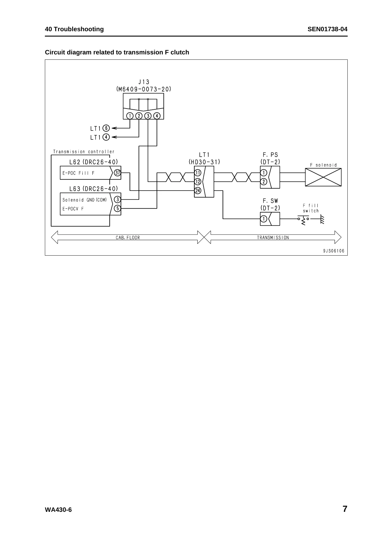
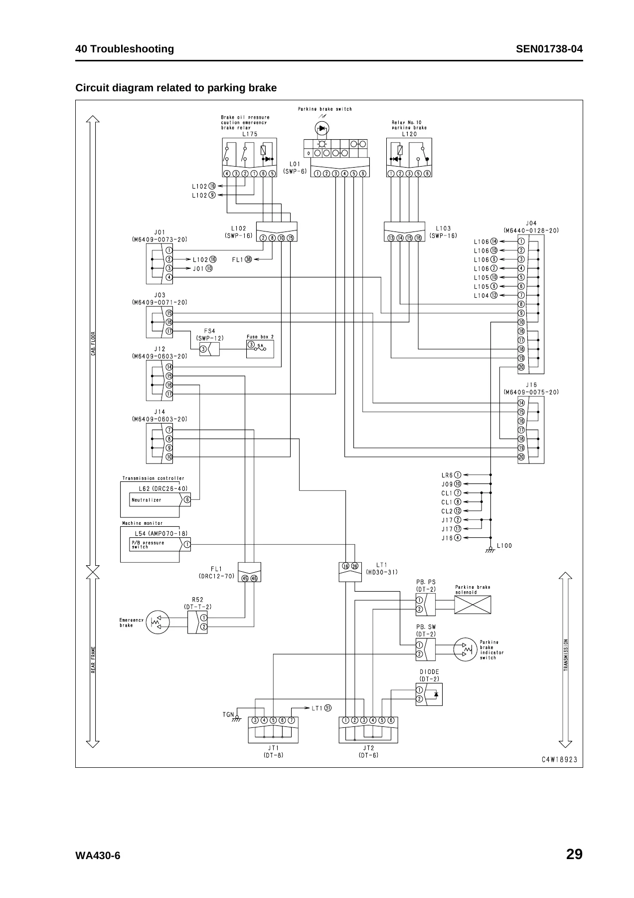
Every major system includes a dedicated circuit diagram showing the complete electrical path from the controller through the wiring harness, connectors, relays, and solenoids. These diagrams identify connector numbers, pin positions, wire colors, and splice points, making it possible to trace faults through the entire circuit. Systems with dedicated diagrams include the transmission F and R clutches, 1st through 4th clutches, parking brake, bucket proximity switches, engine oil pressure switch, coolant temperature sensor, boost pressure and temperature sensors, common rail pressure sensor, throttle sensor, atmospheric pressure sensor, engine Ne and Bkup speed sensors, sensor power supplies, CAN communication, engine controller power supply, ECSS solenoid, backup lamp relay, joystick steering relays, remote positioner switches, load meter switches, fan reverse switch, transmission output shaft speed sensor, and numerous solenoid circuits.
What This Manual Enables You to Do
With this Komatsu WA430-6 troubleshooting manual, you can read and interpret every failure code the machine displays, understand what the controller is detecting and why it responded the way it did, and follow a logical diagnostic path to the root cause. The standard values in each troubleshooting table eliminate guesswork – you know exactly what resistance a fill switch should show, what voltage a sensor signal should produce, and what the controller expects to see at each pin. This means faster diagnosis, fewer replaced parts that were not actually faulty, and more accurate repairs.
For fleet owners and maintenance managers, having the complete failure code reference for the WA430-6 means your technicians can diagnose faults without waiting for dealer support. For independent repair shops, it provides the same diagnostic information the authorized service network uses, formatted for practical use in the shop. For owner-operators, it turns a cryptic error code on the monitor into a clear, step-by-step test procedure you can perform with basic tools.
The manual covers every controller on the WA430-6: transmission, engine, machine monitor, work equipment, and the CAN network that connects them. Whether the fault is a hard failure that prevents the machine from moving or a soft code that only appears under specific conditions, the failure code index and troubleshooting tables give you the path to resolution.
IMAGES PREVIEW
Delivered as an instant PDF download, this Komatsu WA430-6 shop manual is ready to use on any device – laptop, tablet, or smartphone – and can be printed for the shop floor. No shipping, no waiting, no software required. Every page, every diagram, every specification is exactly as Komatsu published it, organized by failure code for quick reference when you need it most.

Reviews
There are no reviews yet.