Description
Komatsu WA600-6R Wheel Loader Shop Manual SEN02211-20 – Serial 65001 and Up
The Komatsu WA600-6R Wheel Loader Shop Manual SEN02211-20 – Serial 65001 and Up is a comprehensive workshop reference for the WA600-6R wheel loader in the serial-number range 65001 and up. Across 2,032 PDF pages, it brings together machine specifications, component structure and function, maintenance standards, standard service values, testing and adjustment procedures, failure-code and symptom-based troubleshooting, disassembly and assembly procedures, and hydraulic and electrical diagrams. The manual is organized around the systems a technician works on in the shop, so the technical data, checks, repair procedures, and circuit information can be followed from diagnosis through component service and final adjustment.
File Details
- Manual type: Shop Manual
- Brand: Komatsu
- Model: WA600-6R Wheel Loader
- Serial number coverage: 65001 and up
- Main form number: SEN02211-20
- Language: English
- Page count: 2,032 pages
- File format: PDF
Machine and Technical Coverage
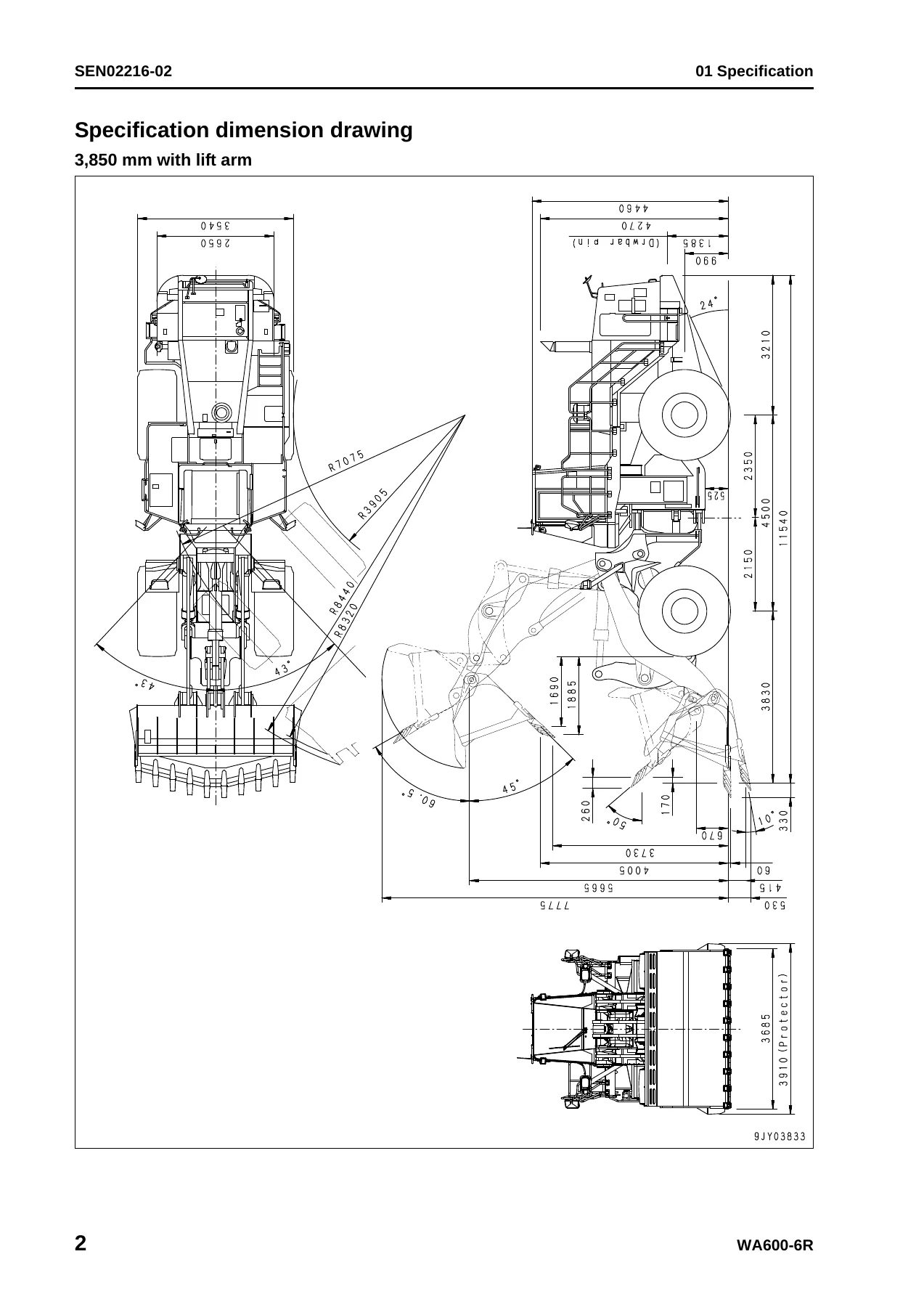
This WA600-6R shop manual identifies the installed engine as the SAA6D170E-5, a 4-cycle, water-cooled direct-injection engine with turbocharger and aftercooler. The specification material covers the engine, power train, wheel and axle system, brakes, steering, hydraulic system, and work equipment. It also includes two lift-arm configurations shown in the specification section: 3,850 mm and 3,990 mm. The corresponding machine data includes operating weight, bucket capacity, rated load, travel speeds, drawbar pull, turning radius, overall dimensions, bucket geometry, and working dimensions.
The engine data gives the 6-cylinder 170 x 170 mm bore and stroke arrangement, 23.15 l {23,150 cc} displacement, output ratings, maximum torque, idle speeds, starting motor, alternator, and battery information. Chassis coverage includes the 3-element, 1-stage, 2-phase torque converter with lockup clutch, planetary multiple-disc transmission with 4 forward and 4 reverse stages, front and rear wheel drive, axle and final-drive construction, fully hydraulic braking, and articulated fully hydraulic power steering. Hydraulic specifications include pump deliveries for the work equipment, steering, fan, torque converter and transmission, cooling, and EPC/brake circuits, together with work-equipment and steering pressure settings and cylinder dimensions.
Fluid information is also included. The manual’s capacity table covers the engine oil pan, transmission case, hydraulic system, front and rear axles, fuel tank, and cooling system, with specified and refill capacities where given. A component weight table supports handling and removal work by listing weights for major assemblies such as the engine, radiator, torque converter, transmission, axles, differentials, hydraulic tank, pumps, cylinders, frames, lift arms, bucket, counterweight, fuel tank, cab, and other serviceable units.
Complete PDF Bookmark Tree
Complete Bookmarks
The complete bookmarks in the “Komatsu WA600-6R Wheel Loader Shop Manual SEN02211-20 – Serial 65001 and Up” are as follows:
COVERp. 1
+00 INDEX AND FOREWORDp. 3
+INDEXp. 3
Composition of shop manualp. 4
Table of contentsp. 6
+FOREWORD AND GENERAL INFORMATIONp. 21
SAFETY NOTICEp. 22
HOW TO READ THE SHOP MANUALp. 27
EXPLANATION OF TERMS FOR MAINTENANCE STANDARDp. 29
HANDLING OF ELECTRIC EQUIPMENT AND HYDRAULIC COMPONENTp. 31
HANDLING OF CONNECTORS NEWLY USED FOR ENGINESp. 40
HOW TO READ ELECTRIC WIRE CODEp. 43
PRECAUTIONS WHEN CARRYING OUT OPERATIONp. 46
METHOD OF DISASSEMBLING AND CONNECTING PUSH-PULL TYPE COUPLERp. 49
STANDARD TIGHTENING TORQUE TABLEp. 52
CONVERSION TABLEp. 56
+01 SPECIFICATIONp. 63
+SPECIFICATION AND TECHNICAL DATAp. 63
SPECIFICATION DIMENSION DRAWINGp. 64
SPECIFICATIONSp. 65
WEIGHT TABLEp. 72
TABLE OF FUEL, COOLANT AND LUBRICANTSp. 74
+10 STRUCTURE, FUNCTION AND MAINTENANCE STANDARDp. 77
+ENGINE AND COOLING SYSTEMp. 77
ENGINE MOUNT AND TRANSMISSION MOUNTp. 78
DAMPERp. 80
COOLING SYSTEMp. 82
COOLING FAN PUMPp. 86
COOLING FAN MOTORp. 94
+POWER TRAIN, PART 1p. 101
POWER TRAINp. 102
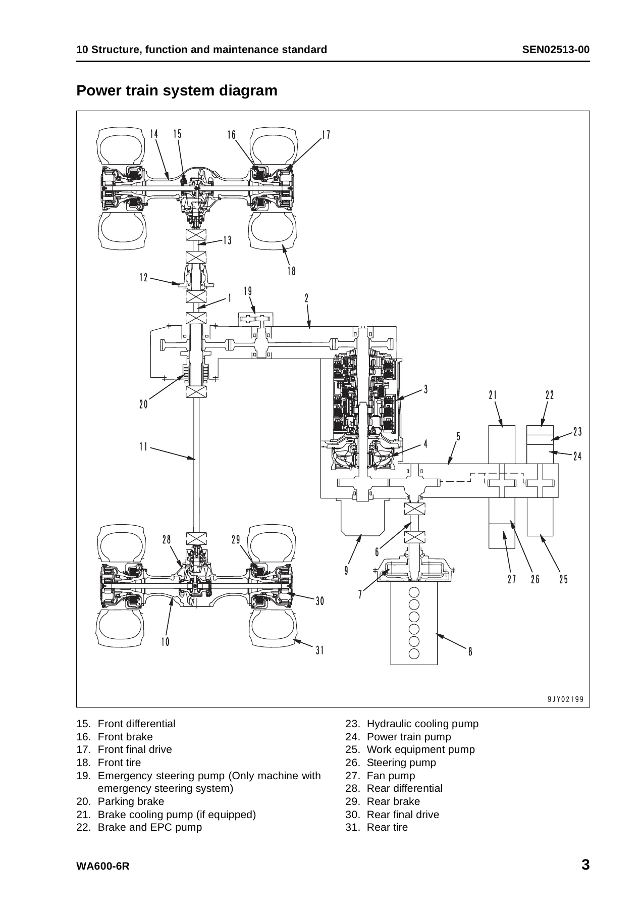
POWER TRAIN SYSTEM DIAGRAMp. 103
TORQUE CONVERTER AND TRANSMISSION PIPING DIAGRAMp. 104
TORQUE CONVERTERp. 106
MODULATION CLUTCHp. 115
TORQUE CONVERTER REGULATOR VALVEp. 116
TRANSMISSIONp. 118
TRANSFERp. 138
TRANSMISSION CONTROL VALVEp. 140
ECMVp. 142
MAIN RELIEF VALVE AND TORQUE CONVERTER RELIEF VALVEp. 149
LUBRICATION RELIEF VALVEp. 151
+POWER TRAIN, PART 2p. 153
TORQUE CONVERTER OIL COOLERp. 154
TORQUE CONVERTER OIL FILTERp. 155
DRIVE SHAFTp. 157
CENTER SUPPORTp. 160
AXLEp. 162
DIFFERENTIALp. 166
LIMITED SLIP DIFFERENTIALp. 175
FINAL DRIVEp. 180
+STEERING SYSTEMp. 185
Steering piping diagramp. 188
Steering columnp. 190
Joystick steering lever linkagep. 191
Joystick EPC valvep. 192
Lock valvep. 193
Steering valvep. 194
Rotary valvep. 197
Steering control valvep. 200
Two-way restrictor valvep. 216
Stop valvep. 217
Steering pumpp. 218
Steering cylinderp. 232
Emergency steering piping diagramp. 234
Diverter valvep. 235
Emergency steering pumpp. 243
+BRAKE SYSTEMp. 245
Brake piping diagramp. 246
Brakep. 248
Brake valvep. 252
Accumulator charge valvep. 260
EPC relief valvep. 266
Accumulator (for brake)p. 268
Slack adjusterp. 270
Parking brakep. 274
Parking brake solenoid valvep. 276
Emergency parking brake release valvep. 278
Brake cooling pumpp. 279
+UNDERCARRIAGE AND FRAMEp. 281
AXLE MOUNTp. 282
CENTER HINGE PINp. 287
+HYDRAULIC SYSTEM, PART 1p. 291
HYDRAULIC PIPING DIAGRAMp. 292
WORK EQUIPMENT CONTROL LEVER LINKAGEp. 294
HYDRAULIC TANKp. 296
WORK EQUIPMENT HYDRAULIC PUMPp. 298
+HYDRAULIC SYSTEM, PART 2p. 319
Control valvep. 320
CLSSp. 334
Each function and operation of each valvep. 339
Accumulator (for PPC circuit)p. 358
Accumulator (for ECSS)p. 359
Triple pumpp. 360
+WORK EQUIPMENTp. 363
Work equipment linkagep. 364
Bucketp. 368
Bucket positioner and boom kick-outp. 372
Work equipment lubricationp. 373
Work equipment cylinderp. 375
+CAB AND ITS ATTACHMENTSp. 379
ROPS CABp. 380
AIR CONDITIONERp. 382
+ELECTRICAL SYSTEM, PART 1p. 387
Machine monitor systemp. 388
Machine monitorp. 394
+ELECTRICAL SYSTEM, PART 2p. 451
WORK EQUIPMENT CONTROL SYSTEMp. 452
TRANSMISSION CONTROLLER SYSTEMp. 488
+ELECTRICAL SYSTEM, PART 3p. 521
Electric transmission controlp. 522
Engine starting/stopping circuitp. 524
Parking brake circuitp. 527
Sensorp. 531
VHMS controller relatedp. 554
VHMS controller and wireless LAN systemp. 555
Work equipment electric leverp. 561
+20 STANDARD VALUE TABLEp. 565
+STANDARD SERVICE VALUE TABLEp. 565
Standard service value table for enginep. 566
Standard service value table for chassisp. 567
+30 TESTING AND ADJUSTINGp. 577
+TESTING AND ADJUSTING, PART 1p. 577
Tools for testing, adjusting, and troubleshootingp. 579
Measuring engine speedp. 585
Measuring exhaust gas colorp. 587
Measuring exhaust temperaturep. 588
Adjusting valve clearancep. 590
Testing compression pressuresp. 592
Measuring blow-by pressurep. 595
Measuring engine oil pressurep. 596
Measuring intake air (boost) pressurep. 597
Handling fuel system equipmentp. 598
Releasing residual pressure in fuel systemp. 598
Testing fuel pressuresp. 599
Testing return rate and leakagep. 600
Bleeding air from fuel circuitp. 603
Testing leakage in fuel systemp. 605
Handling reduced cylinder mode operationp. 606
Handling no-injection cranking operationp. 606
Handling controller voltage circuitp. 607
Replacing and adjusting alternator and air conditioner compressor belt tensionp. 608
Adjusting modulation clutch speed sensor and speed sensorp. 609
Measuring directional lever (Steering wheel specification)p. 611
Testing and adjusting power train oil pressurep. 612
Flushing procedure for torque converter and transmission hydraulic circuitp. 626
Method of moving machine when transmission valve is brokenp. 628
Adjusting steering stop valvep. 630
+TESTING AND ADJUSTING, PART 2p. 633
Measuring operating effort of AJSS lever (AJSS specification)p. 635
Testing and adjusting AJSS lever angle sensor and frame angle sensor (AJSS specification)p. 636
Testing and adjusting steering stopper bolt (AJSS specification)p. 638
Testing and adjusting steering wheel (Steering wheel specification)p. 640
Testing steering oil pressurep. 642
Bleeding air from steering cylinder circuitp. 646
Testing hydraulic drive fanp. 647
Bleeding air from hydraulic drive fan circuitp. 650
Measuring brake pedalp. 652
Measuring brake performancep. 653
Testing and adjusting accumulator charge pressurep. 654
Testing of accumulator nitrogen gas pressure and procedure for charging brake accumulator with nitrogen gasp. 656
Testing wheel brake oil pressurep. 664
Measuring wear of wheel brake discp. 666
Bleeding air from wheel brake circuitp. 667
Releasing residual pressure in brake accumulator circuitp. 668
Testing parking brake performancep. 669
Measuring parking brake oil pressurep. 670
Testing wear of parking brake discp. 673
Method of releasing parking brake manuallyp. 674
Measuring and adjusting work equipment control leverp. 675
Measuring work equipment oil pressurep. 676
Bleeding air from work equipment circuitp. 681
Releasing residual pressure in work equipment circuitp. 682
Testing of accumulator nitrogen gas pressure and procedure for charging ECSS accumulator with nitrogen gasp. 684
Moving machine for removing operator cabp. 692
Testing and adjusting bucket positionerp. 694
Testing and adjusting lift arm position detecting leverp. 696
Checking proximity switch operation indication lampp. 697
Preparations for work on troubleshooting of electric systemp. 698
Procedure for testing diodesp. 702
+TESTING AND ADJUSTING, PART 3p. 705
Machine monitor-based adjustment at replacement, disassembly and assembly, and additional installation for each sensor and controllerp. 706
Special functions of machine monitor (EMMS)p. 709
+TESTING AND ADJUSTING, PART 4p. 785
VHMS controller initial setting procedure (ORBCOMM installation specification)p. 786
VHMS controller initial setting procedure (IRIDIUM installation specification)p. 808
Precautions for replacing VHMS controllerp. 830
Initialization of VHMS wireless LAN modem and downloading of datap. 836
Pm-clinic inspection tablep. 843
+40 TROUBLESHOOTINGp. 847
+FAILURE CODE TABLE AND FUSE LOCATIONSp. 847
Failure codes listp. 848
Fuse locationsp. 860
+GENERAL INFORMATION ON TROUBLESHOOTINGp. 863
Points to remember when performing troubleshootingp. 864
How to proceed in troubleshootingp. 866
Testing before troubleshootingp. 868
Classification and procedures of troubleshootingp. 869
Information in troubleshooting tablep. 873
Troubleshooting method for disconnecting wiring harness of pressure sensor systemp. 875
Phenomena looking like troubles and troubleshooting Nos.p. 878
Connection table for connector pin numbersp. 880
T- branch box and T- branch adapter tablep. 915
+TROUBLESHOOTING BY FAILURE CODE (DISPLAY OF CODE), PART 1p. 919
Failure code [1500L0] TORQFLOW transmission: Double meshingp. 921
Failure code [15B0NX] Transmission Oil Filter Cloggingp. 922
Failure code [15SAL1] ECMV F clutch: When command current is OFF, fill signal is ONp. 924
Failure code [15SALH] ECMV F clutch: When command current is ON, fill signal is OFFp. 926
Failure code [15SBL1] ECMV R clutch: When command current is OFF, fill signal is ONp. 928
Failure code [15SBLH] ECMV R clutch: When command current is ON, fill signal is OFFp. 930
Failure code [15SEL1] ECMV (1): When command current is OFF, fill signal is ONp. 932
Failure code [15SELH] ECMV (1): When command current is ON, fill signal is OFFp. 934
Failure code [15SFL1] ECMV (2): When command current is OFF, fill signal is ONp. 936
Failure code [15SFLH] ECMV (2): When command current is ON, fill signal is OFFp. 938
Failure code [15SGL1] ECMV (3): When command current is OFF, fill signal is ONp. 940
Failure code [15SGLH] ECMV (3): When command current is ON, fill signal is OFFp. 942
Failure code [15SHL1] ECMV (4): When command current is OFF, fill signal is ONp. 944
Failure code [15SHLH] ECMV (4): When command current is ON, fill signal is OFFp. 946
Failure code [15W0NT] Transmission modulation clutch: Overheatingp. 948
Failure code [2F00MA] Parking brake: Malfunctionp. 949
Failure code [2G42ZG] Front Accumulator Oil Pressure Lowp. 952
+TROUBLESHOOTING BY FAILURE CODE (DISPLAY OF CODE), PART 2p. 955
Failure code [2G43ZG] Rear Accumulator Oil Pressure Lowp. 958
Failure code [44K0L4] Bucket positioner: ON/OFF signals disagreep. 960
Failure code [A000N1] (or VHMS_LED display: “n2” → “01”) Engine: Overrunp. 963
Failure code [AA1ANX] Air Cleaner Cloggingp. 964
Failure code [AB00L6] Alternator: Signal disagrees with run and stop of enginep. 966
Failure code [AB00MA] Alternator: Malfunctionp. 968
Failure code [B@BAZG] Engine oil pressure: Low errorp. 970
Failure code [B@BAZK] Eng Oil Level Lowp. 971
Failure code [B@BCNS] Engine coolant temperature: Overheatingp. 972
Failure code [B@BCZK] Engine coolant level lowp. 974
Failure code [B@C7NS] Brake oil overheatingp. 976
Failure code [b@CENS] Torque converter oil overheatingp. 977
Failure code [B@CENS] Torque converter oil overheatingp. 978
Failure code [B@GAZK] Low Battery Fluid Levelp. 979
Failure code [B@HANS] Hyd Oil Overheatp. 981
Failure code [CA111] Abnormality in engine controllerp. 982
Failure code [CA115] Engine Ne or Bkup speed sensor errorp. 985
Failure code [CA122] Charge (boost) pressure sensor high errorp. 986
Failure code [CA123] Charge (boost) pressure sensor low errorp. 988
Failure code [CA131] Throttle sensor high errorp. 990
Failure code [CA132] Throttle sensor low errorp. 993
Failure code [CA135] Engine oil pressure sensor high errorp. 996
Failure code [CA141] Engine oil pressure sensor low errorp. 998
Failure code [CA144] Coolant temperature sensor high errorp. 1000
Failure code [CA145] Coolant temperature sensor low errorp. 1002
Failure code [CA153] Charge (boost) temperature sensor high errorp. 1004
Failure code [CA154] Charge (boost) temperature sensor low errorp. 1006
Failure code [CA187] Sensor power supply 2 low errorp. 1008
Failure code [CA212] Engine oil temperature sensor high errorp. 1010
Failure code [CA213] Engine oil temperature sensor low errorp. 1012
Failure code [CA221] Atmospheric pressure sensor high errorp. 1014
Failure code [CA222] Atmospheric pressure sensor low errorp. 1016
Failure code [CA227] Sensor power supply 2 high errorp. 1018
+TROUBLESHOOTING BY FAILURE CODE (DISPLAY OF CODE), PART 3p. 1021
Failure code [CA234] Engine overspeedp. 1023
Failure code [CA238] Ne speed sensor power supply errorp. 1024
Failure code [CA263] Fuel temperature sensor high errorp. 1026
Failure code [CA265] Fuel temperature sensor low errorp. 1028
Failure code [CA271] PCV1 Short circuitp. 1030
Failure code [CA272] PCV1 Disconnectionp. 1031
Failure code [CA273] PCV2 Short circuitp. 1032
Failure code [CA274] PCV2 Disconnectionp. 1033
Failure code [CA322] Injector #1 open/short errorp. 1034
Failure code [CA323] Injector #5 open/short errorp. 1036
Failure code [CA324] Injector #3 open/short errorp. 1038
Failure code [CA325] Injector #6 open/short errorp. 1040
Failure code [CA331] Injector #2 open/short errorp. 1042
Failure code [CA332] Injector #4 open/short errorp. 1044
Failure code [CA342] Calibration code inconsistencyp. 1046
Failure code [CA351] Injectors drive circuit errorp. 1047
Failure code [CA352] Sensor power supply 1 low errorp. 1048
Failure code [CA386] Sensor power supply 1 high errorp. 1050
Failure code [CA431] Idle validation switch errorp. 1051
Failure code [CA432] Idle validation action errorp. 1054
Failure code [CA441] Battery voltage low errorp. 1057
Failure code [CA442] Battery voltage high errorp. 1058
Failure code [CA449] Common rail pressure high error 2p. 1059
Failure code [CA451] Common rail pressure sensor high errorp. 1060
Failure code [CA452] Common rail pressure sensor low errorp. 1062
Failure code [CA553] Common rail pressure high error 1p. 1064
Failure code [CA554] Common rail pressure sensor in range errorp. 1065
Failure code [CA559] Supply pump pressure very low error 1p. 1066
Failure code [CA689] Engine Ne speed sensor errorp. 1070
Failure code [CA731] Engine Bkup speed sensor phase errorp. 1072
Failure code [CA757] All continuous data lost errorp. 1073
Failure code [CA778] Engine Bkup speed sensor errorp. 1074
Failure code [CA1633] KOMNET datalink timeout errorp. 1076
+TROUBLESHOOTING BY FAILURE CODE (DISPLAY OF CODE), PART 4p. 1079
Failure code [CA2185] Throttle sensor supply voltage high errorp. 1082
Failure code [CA2186] Throttle sensor power supply low errorp. 1084
Failure code [CA2249] Supply pump pressure very low error 2p. 1086
Failure code [CA2555] Intake air heater relay open circuit errorp. 1088
Failure code [CA2556] Intake air heater relay short circuit errorp. 1090
Failure code [D191KA] AJSS neutral safety relay open circuitp. 1092
Failure code [D191KB] AJSS neutral safety relay short circuitp. 1094
Failure code [D192KA] ECSS solenoid: Disconnectionp. 1096
Failure code [D192KB] ECSS solenoid: Short circuitp. 1097
Failure code [D192KY] ECSS solenoid: Short circuit with power supply linep. 1098
Failure code [D198KA] Transmission oil pressure bypass solenoid: Disconnectionp. 1099
Failure code [D198KB] Transmission oil pressure bypass solenoid: Short circuitp. 1100
Failure code [D198KY] Transmission oil pressure bypass solenoid: Short circuit with power supply linep. 1101
Failure code [D5ZHKA] Terminal C signal open circuitp. 1102
Failure code [D5ZHKB] Terminal C signal short circuitp. 1104
Failure code [D5ZHKZ] Terminal C signal open or short circuitp. 1106
Failure code [D5ZHL6] Terminal C signal disagrees with run and stop of enginep. 1108
Failure code [DA80L4] Auto-greasing controller disagrees with ON/OFF signalp. 1110
Failure code [DAF3KK] Machine monitor: Source voltage low (input)p. 1112
Failure code [DAF5KP] Machine monitor: Output voltage lowp. 1114
Failure code [DAFRKR] CAN communication with machine monitor: Communication error (Abnormality in target component system)p. 1116
Failure code [DAQ0KK] Transmission controller: Source voltage lowp. 1117
Failure code [DAQ0KT] Transmission controller: Defect in controllerp. 1120
Failure code [DAQ2KK] Transmission controller load power supply line: Source voltage low (Input)p. 1121
Failure code [DAQ9KQ] Transmission controller model selection: Model selection signal disagreementp. 1124
Failure code [DAQRKR] CAN communication with transmission controller: Communication error (Abnormality in target component system)p. 1125
Failure code [DAQRMA] Transmission controller (Option setting): Malfunctionp. 1130
+TROUBLESHOOTING BY FAILURE CODE (DISPLAY OF CODE), PART 5p. 1133
Failure code [DB2RKR] CAN communication from engine controller: Communication error (Abnormality in target component system)p. 1136
Failure code [DB90KK] Work equipment controller: Source voltage low (input)p. 1139
Failure code [DB90KT] Work equipment controller: Defect in controllerp. 1142
Failure code [DB92KK] Work equipment controller load power supply line: Source voltage low (input)p. 1143
Failure code [DB95KX] Work equipment controller power supply output: Out of rangep. 1146
Failure code [DB99KQ] Work equipment controller model selection: Model selection signal disagreementp. 1148
Failure code [DB9RKR] CAN communication with work equipment controller: Communication error (Abnormality in target component system)p. 1149
Failure code [DB9RMA] Work equipment controller (Option setting): Malfunctionp. 1150
Failure code [DB9RMC] CAN communication with transmission controller: Malfunctionp. 1151
Failure code [DBB0KK] or change of VHMS_LED display from "n9" to "01" (VHMS controller: Source voltage low (input))p. 1152
Failure code [DBB0KQ] or change of VHMS_LED display from "nF" to "11" (VHMS controller: Disagreement of model selection signals)p. 1154
Failure code [DBB3KK] or change of VHMS_LED display from "n9" to "05" (VHMS controller battery power supply: Source voltage low (input))p. 1156
Failure code [DBB5KP] or change of VHMS_LED display from "n9" to "04" (VHMS controller 5 V power supply output: Output voltage low)p. 1158
Failure code [DBB6KP] or change of VHMS_LED display from "n9" to "02" (VHMS controller 24V power supply output: Output voltage low)p. 1160
Failure code [DBB7KP] or change of VHMS_LED display from "n9" to "03" (VHMS controller 12V power supply output: Output voltage low)p. 1162
Failure code [DBBQKR] or change of VHMS_LED display from "n8" to "02" (CAN communication of VHMS controller: Communication error (Abnormality in target component system))p. 1164
Failure code [DD15LD] t switch (Panel switch 1): Switch is kept pressed for long timep. 1166
Failure code [DD16LD] U switch (Panel switch 2): Switch is kept pressed for long timep. 1168
Failure code [DD17LD] < switch (Panel switch 3): Switch is kept pressed for long timep. 1170
Failure code [DD18LD] > switch (Panel switch 4): Switch is kept pressed for long timep. 1172
Failure code [DD1ALD] Remote positioner raise/lower set switch (raise): Switch is kept pressed for long timep. 1174
Failure code [DD1BLD] Remote positioner raise/lower set switch (lower): Switch is kept pressed for long timep. 1176
Failure code [DD1CLD] Load meter subtotal switch: Switch is kept pressed for long timep. 1178
Failure code [DD1FLD] Load meter mode selector switch (A/B): Switch is kept pressed for long timep. 1180
Failure code [DD1GLD] Load meter mode selector switch (+/–): Switch is kept pressed for long timep. 1182
+TROUBLESHOOTING BY FAILURE CODE (DISPLAY OF CODE), PART 6p. 1185
Failure code [DD1HLD] Load meter display selector switch: Switch is kept pressed for long timep. 1188
Failure code [DDA7L4] RPM set ON/OFF switch: ON-OFF signals disagreep. 1190
Failure code [DDA8KB] RPM set idle-up/down selector switch (idle-up): Short circuitp. 1192
Failure code [DDA9KB] RPM set idle-up/down selector switch (idle-down): Short circuitp. 1195
Failure code [DDD1LD] Remote positioner bucket angle set switch: Switch is kept pressed for long timep. 1198
Failure code [DDDBKA] Traction adjustment dial: Disconnectionp. 1202
Failure code [DDDBKB] Traction adjustment dial: Short circuitp. 1204
Failure code [DDE5MA] Emergency steering drive switch: Malfunctionp. 1206
Failure code [DDK4KA] AJSS FNR switch: Disconnectionp. 1208
Failure code [DDK4KB] AJSS FNR switch: Short circuitp. 1210
Failure code [DDK5L4] AJSS shift-up/down switch: ON/OFF signals disagreep. 1212
Failure code [DDK6KA] FNR lever switch: Disconnectionp. 1215
Failure code [DDK6KB] FNR lever switch: Short circuitp. 1218
Failure code [DDP5KA] Lock detection pressure switch of steering lock lever: Disconnectionp. 1220
Failure code [DDT0L4] Shift mode selector switch: ON/OFF signals disagreep. 1222
Failure code [DDW9LD] Kick-down switch: Switch is kept pressed for long timep. 1224
Failure code [DDWLLD] Hold switch: Switch is kept pressed for long timep. 1226
Failure code [DDY0LD] Load meter cancel switch: Switch is kept pressed for long timep. 1228
Failure code [DF10KA] Transmission shift lever switch: Disconnectionp. 1230
Failure code [DF10KB] Transmission shift lever switch: Short circuitp. 1234
Failure code [DGE5KX] (or VHMS_LED display: “n4” → “01”) Atmospheric temperature sensor: Out of input signal rangep. 1236
Failure code [DGF1KA] Transmission oil temperature sensor: Disconnectionp. 1238
Failure code [DGF1KB] Transmission oil temperature sensor: Short circuitp. 1240
+TROUBLESHOOTING BY FAILURE CODE (DISPLAY OF CODE), PART 7p. 1243
Failure code [DGH2KX] Hydraulic oil temperature sensor: Out of input signal rangep. 1246
Failure code [DGR2KA] Rear brake oil temperature sensor: Disconnectionp. 1248
Failure code [DGR2KX] Rear brake oil temperature sensor: Out of input signal rangep. 1250
Failure code [DGT1KA] Torque converter oil temperature sensor: Disconnectionp. 1252
Failure code [DGT1KB] Torque converter oil temperature sensor: Short circuitp. 1253
Failure code [DGT1KX] Torque converter oil temperature sensor: Out of input signal rangep. 1254
Failure code [DGT4KA] (or VHMS_LED display: "n3" → "12") Exhaust gas temperature sensor (F): Disconnectionp. 1256
Failure code [DGT4KB] (or VHMS_LED display: "n3" → "11") Exhaust gas temperature sensor (F): Short circuitp. 1259
Failure code [DGT5KA] (or VHMS_LED display: "n3" → "22") Exhaust gas temperature sensor (R): Disconnectionp. 1262
Failure code [DGT5KB] (or VHMS_LED display: "n3" → "21") Exhaust gas temperature sensor (R): Short circuitp. 1265
Failure code [DH21KA] Work equipment pump oil pressure sensor: Disconnectionp. 1268
Failure code [DH21KB] Work equipment pump oil pressure sensor: Short circuitp. 1270
Failure code [DHE5KB] (or VHMS_LED display: “n3” → “32”) Blow-by pressure sensor: Short circuitp. 1272
Failure code [DHE5KY] (or VHMS_LED display: “n3” → “31”) Blow-by pressure sensor: Short circuit with power supply linep. 1274
Failure code [DHPCKX] Lift arm cylinder bottom pressure sensor: Out of input signal rangep. 1276
Failure code [DHPDKX] Lift arm cylinder head pressure sensor: Out of input signal rangep. 1279
Failure code [DHT2L6] Transmission filter clogging sensor: Signal disagrees with operating state of enginep. 1282
Failure code [DHT8KX] (or VHMS_LED display: “n5” → “33”) Steering oil pressure sensor: Out of input signal rangep. 1284
Failure code [DHTBKA] Modulation clutch oil pressure sensor: Disconnectionp. 1288
Failure code [DHTBKB] Modulation clutch oil pressure sensor: Short circuitp. 1290
Failure code [DHU2KX] (or VHMS_LED display: “n7” → “11”) Front brake oil pressure sensor (F): Out of input signal rangep. 1292
Failure code [DHU3KX] (or VHMS_LED display: “n7” → “12”) Rear brake oil pressure sensor (R): Out of input signal rangep. 1294
Failure code [DK30KA] AJSS lever angle sensor: Disconnectionp. 1296
Failure code [DK30KY] AJSS lever angle sensor: Short circuit with power supply linep. 1298
+TROUBLESHOOTING BY FAILURE CODE (DISPLAY OF CODE), PART 8p. 1301
Failure code [DK59KA] Lift arm EPC lever potentiometer (Main): Disconnectionp. 1303
Failure code [DK59KY] Lift arm EPC lever potentiometer (Main): Short circuit with power supply linep. 1306
Failure code [DK59L8] Lift arm EPC lever potentiometer (Main): Analog signals disagreep. 1308
Failure code [DK5AKA] Lift arm EPC lever potentiometer (Sub): Disconnectionp. 1312
Failure code [DK5AKY] Lift arm EPC lever potentiometer (Sub): Short circuit with power supply linep. 1315
Failure code [DK5BKA] Bucket EPC lever potentiometer (Main): Disconnectionp. 1318
Failure code [DK5BKY] Bucket EPC lever potentiometer (Main): Short circuit with power supply linep. 1321
Failure code [DK5BL8] Bucket EPC lever potentiometer (Main): Analog signals disagreep. 1323
Failure code [DK5CKA] Bucket EPC lever potentiometer (Sub): Disconnectionp. 1327
Failure code [DK5CKY] Bucket EPC lever potentiometer (Sub): Short circuit with power supply linep. 1330
Failure code [DK5DKA] 3-spool valve (attachment) EPC lever potentiometer (Main): Disconnectionp. 1333
Failure code [DK5DKY] 3-spool valve (attachment) EPC lever potentiometer (Main): Short circuit with power supply linep. 1336
Failure code [DK5DL8] 3-spool valve (attachment) EPC lever potentiometer (Main): Analog signals disagreep. 1338
Failure code [DK5EKA] 3-spool valve (attachment) EPC lever potentiometer (Sub): Disconnectionp. 1341
Failure code [DK5EKY] 3-spool valve EPC lever potentiometer (Sub): Short circuit with power supply linep. 1344
Failure code [DKA0KA] Lift arm angle sensor: Disconnectionp. 1346
Failure code [DKA0KX] Lift arm angle sensor: Out of input signal rangep. 1349
Failure code [DKA0KY] Lift arm angle sensor: Short circuit with power supply linep. 1350
Failure code [DKA0L0] Lift arm angle sensor: Improper positionp. 1352
+TROUBLESHOOTING BY FAILURE CODE (DISPLAY OF CODE), PART 9p. 1355
Failure code [DKD0KA] Frame angle sensor: Disconnectionp. 1358
Failure code [DKD0KY] Frame angle sensor: Short circuit with power supply linep. 1360
Failure code [DKD0KZ] AJSS lever and frame angle sensor: Disconnection or short circuitp. 1362
Failure code [DLFAKA] Modulation clutch output shaft speed sensor: Disconnectionp. 1366
Failure code [DLFALC] Modulation clutch output shaft speed sensor: Speed signals disagreep. 1368
Failure code [DLT3KA] Transmission output shaft speed sensor (2): Disconnectionp. 1370
Failure code [DLT3LC] Transmission output shaft speed sensor (2): Speed signals disagreep. 1372
Failure code [DLT4KB] Transmission output shaft speed sensor (1): Short circuitp. 1374
Failure code [DLT4KX] Transmission output shaft speed sensor (1): Out of input signal rangep. 1376
Failure code [DUM1KB] Remote positioner raise indicator lamp: Short circuitp. 1378
Failure code [DUM2KB] Remote positioner lower indicator lamp: Short circuitp. 1380
Failure code [DV00KB] Alarm buzzer: Short circuitp. 1382
Failure code [DW4PKA] Lift arm raise EPC solenoid: Disconnectionp. 1384
Failure code [DW4PKB] Lift arm raise EPC solenoid: Short circuitp. 1386
Failure code [DW4PKY] Lift arm raise EPC solenoid: Short circuit with power supply linep. 1387
Failure code [DW4QKA] Lift arm lower EPC solenoid: Disconnectionp. 1388
Failure code [DW4QKB] Lift arm lower EPC solenoid: Short circuitp. 1389
Failure code [DW4QKY] Lift arm lower EPC solenoid: Short circuit with power supply linep. 1390
Failure code [DW4RKA] Bucket tilt EPC solenoid: Disconnectionp. 1391
Failure code [DW4RKB] Bucket tilt EPC solenoid: Short circuitp. 1392
Failure code [DW4RKY] Bucket tilt EPC solenoid: Short circuit with power supply linep. 1393
Failure code [DW4SKA] Bucket dump EPC solenoid: Disconnectionp. 1394
Failure code [DW4SKB] Bucket dump EPC solenoid: Short circuitp. 1395
Failure code [DW4SKY] Bucket dump EPC solenoid: Short circuit with power supply linep. 1396
Failure code [DW7BKA] Fan reverse solenoid: Disconnectionp. 1398
Failure code [DW7BKB] Fan reverse solenoid: Short circuitp. 1400
Failure code [DW7BKY] Fan reverse solenoid: Short circuit with power supply linep. 1402
Failure code [DW7DKA] Hydraulic drive fan neutral solenoid: Disconnectionp. 1403
Failure code [DW7DKB] Hydraulic drive fan neutral solenoid: Short circuitp. 1404
Failure code [DW7DKY] Hydraulic drive fan neutral solenoid: Short circuit with power supply linep. 1405
+TROUBLESHOOTING BY FAILURE CODE (DISPLAY OF CODE), PART 10p. 1407
Failure code [DWM1KA] Work equipment neutral lock solenoid: Disconnectionp. 1410
Failure code [DWM1KB] Work equipment neutral lock solenoid: Short circuitp. 1412
Failure code [DWM1KY] Work equipment neutral lock solenoid: Short circuit with power supply linep. 1414
Failure code [DWN6KA] Lift arm raise magnet detent solenoid: Disconnectionp. 1416
Failure code [DWN6KB] Lift arm raise magnet detent solenoid: Short circuitp. 1418
Failure code [DWN6KY] Lift arm raise magnet detent solenoid: Short circuit with power supply linep. 1420
Failure code [DWN7KA] Lift arm float magnet detent solenoid: Disconnectionp. 1422
Failure code [DWN7KB] Lift arm float magnet detent solenoid: Short circuitp. 1424
Failure code [DWN7KY] Lift arm float magnet detent solenoid: Short circuit with power supply linep. 1426
Failure code [DWN8KA] Bucket tilt magnet detent solenoid: Disconnectionp. 1428
Failure code [DWN8KB] Bucket tilt magnet detent solenoid: Short circuitp. 1430
Failure code [DWN8KY] Bucket tilt magnet detent solenoid: Shorted with the power sourcep. 1432
Failure code [DWNFKA] Modulation clutch cut-off release solenoid: Disconnectionp. 1434
Failure code [DWNFKB] Modulation clutch cut-off release solenoid: Short circuitp. 1436
Failure code [DWNFKY] Modulation clutch cut-off release solenoid: Short circuit with power source linep. 1438
Failure code [DX16KA] Fan pump EPC solenoid: Disconnectionp. 1440
Failure code [DX16KB] Fan pump EPC solenoid: Short circuitp. 1441
Failure code [DX16KY] Fan pump EPC solenoid: Short circuit with power supply linep. 1442
Failure code [DXA1KA] Pump PC-EPC solenoid: Disconnectionp. 1443
Failure code [DXA1KB] Pump PC-EPC solenoid: Short circuitp. 1444
Failure code [DXF0KA] AJSS EPC solenoid: Disconnectionp. 1445
Failure code [DXF0KB] AJSS EPC solenoid: Short circuitp. 1446
Failure code [DXH1KA] Lockup ECMV solenoid: Disconnectionp. 1448
Failure code [DXH1KB] Lockup ECMV solenoid: Short circuitp. 1450
Failure code [DXH1KY] Lockup ECMV solenoid: Short circuit with power supply linep. 1452
Failure code [DXH4KA] 1st clutch ECMV solenoid: Disconnectionp. 1454
Failure code [DXH4KB] 1st clutch ECMV solenoid: Short circuitp. 1456
Failure code [DXH4KY] 1st clutch ECMV solenoid: Short circuit with power supply linep. 1458
+TROUBLESHOOTING BY FAILURE CODE (DISPLAY OF CODE), PART 11p. 1461
Failure code [DXH5KA] 2nd clutch ECMV solenoid: Disconnectionp. 1464
Failure code [DXH5KB] 2nd clutch ECMV solenoid: Short circuitp. 1466
Failure code [DXH5KY] 2nd clutch ECMV solenoid: Short circuit with power supply linep. 1468
Failure code [DXH6KA] 3rd clutch ECMV solenoid: Disconnectionp. 1470
Failure code [DXH6KB] 3rd clutch ECMV solenoid: Short circuitp. 1472
Failure code [DXH6KY] 3rd clutch ECMV solenoid: Short circuit with power supply linep. 1474
Failure code [DXH7KA] R clutch ECMV solenoid: Disconnectionp. 1476
Failure code [DXH7KB] R clutch ECMV solenoid: Short circuitp. 1478
Failure code [DXH7KY] R clutch ECMV solenoid: Short circuit with power supply linep. 1480
Failure code [DXH8KA] F clutch ECMV solenoid: Disconnectionp. 1482
Failure code [DXH8KB] F clutch ECMV solenoid: Short circuitp. 1484
Failure code [DXH8KY] F clutch ECMV solenoid: Short circuit with power supply linep. 1486
Failure code [DXHHKA] 4th clutch ECMV solenoid: Disconnectionp. 1488
Failure code [DXHHKB] 4th clutch ECMV solenoid: Short circuitp. 1490
Failure code [DXHHKY] 4th clutch ECMV solenoid: Short circuit with power supply linep. 1492
Failure code [DXHJKA] 3-spool valve extract EPC solenoid: Disconnectionp. 1494
Failure code [DXHJKB] 3-spool valve extract EPC solenoid: Short circuitp. 1496
Failure code [DXHJKY] 3-spool valve extract EPC solenoid: Short circuit with power supply linep. 1497
Failure code [DXHKKA] 3-spool valve retract EPC solenoid: Disconnectionp. 1498
Failure code [DXHKKB] 3-spool valve retract EPC solenoid: Short circuitp. 1500
Failure code [DXHKKY] 3-spool valve retract EPC solenoid: Short circuit with power supply linep. 1501
Failure code [DXHPKA] Modulation clutch solenoid: Disconnectionp. 1502
Failure code [DXHPKB] Modulation clutch solenoid: Short circuitp. 1504
Failure code [DXHPKY] Modulation clutch solenoid: Short circuit with power source linep. 1506
Failure code [DXHPMA] Modulation clutch solenoid: Malfunctionp. 1508
Failure code [F@BBZL] (or VHMS_LED display: “n3” o “38”) Blow-by pressure: High errorp. 1510
Failure code [F@BYNR] (or VHMS_LED display: “n3” → “62”) Exhaust gas temperature (F): Abnormal heatp. 1512
Failure code [F@BYNS] (or VHMS_LED display: “n3” → “61”) Exhaust gas temperature (F): Overheatp. 1514
Failure code [F@BZNR] (or VHMS_LED display: “n3” → “72”) Exhaust gas temperature (R): abnormal heatp. 1516
Failure code [F@BZNS] (or VHMS_LED display “n3” → “71”) Exhaust gas temperature (R): Overheatp. 1518
+TROUBLESHOOTING OF ELECTRICAL SYSTEM (E-MODE)p. 1521
Before carrying out troubleshooting of electrical systemp. 1524
Information in troubleshooting tablep. 1527
E-1 Engine does not start.p. 1528
E-2 Wiper does not operatep. 1538
E-3 Windshield washer does not operatep. 1546
E-4 Headlamp, clearance lamp, tail lamp, and license lamp do not light up or go offp. 1552
E-5 Working lamp does not light up or go off.p. 1566
E-6 Step lamp does not light up or go offp. 1572
E-7 Turn signal lamp and hazard lamp do not light up or go offp. 1574
E-8 Brake lamp does not light or it keeps lighting up.p. 1584
E-9 Backup lamp does not light or it keeps lighting up.p. 1586
E-10 Backup buzzer does not sound or it keeps sounding.p. 1590
E-11 Horn does not sound or it keeps sounding.p. 1594
E-12 Alarm buzzer does not sound or it keeps soundingp. 1598
E-13 Air conditioner does not operate or stopp. 1600
E-14 Electric priming pump does not operate or does not stop automaticallyp. 1602
E-15 When starting switch is turned to ON position, machine monitor displays nothingp. 1604
+TROUBLESHOOTING OF HYDRAULIC AND MECHANICAL SYSTEM (H-MODE)p. 1609
METHOD OF USING TROUBLESHOOTING CHARTp. 1612
TABLE OF FAILURE MODES AND CAUSESp. 1614
H-1 MACHINE DOES NOT STARTp. 1618
H-2 TORQUE CONVERTER LOCKUP IS NOT SWITCHED (ENGINE STALLS)p. 1620
H-3 TORQUE CONVERTER LOCKUP IS NOT TURNED ONp. 1621
H-4 TRAVEL SPEED IS SLOW, THRUSTING FORCE IS WEAK, UPHILL TRAVELING POWER IS WEAK, AND GEAR IS NOT SHIFTEDp. 1622
H-5 SHOCKS ARE LARGE AT THE TIMES OF STARTING AND SHIFTING GEARp. 1624
H-6 TIME LAG IS LARGE AT THE TIMES OF STARTING AND SHIFTING GEARp. 1626
H-7 TORQUE CONVERTER OIL TEMPERATURE IS HIGHp. 1628
H-8 STEERING DOES NOT TURN [MACHINE WITH STEERING WHEEL]p. 1629
H-9 STEERING DOES NOT TURN [MACHINE WITH AJSS]p. 1630
H-10 TURNING, RESPONSE OF STEERING IS POOR [MACHINE WITH STEERING WHEEL]p. 1631
H-11 TURNING, RESPONSE OF AJSS IS POOR [MACHINE WITH AJSS]p. 1632
H-12 STEERING IS HEAVY [MACHINE WITH STEERING WHEEL]p. 1633
H-13 WHEN MACHINE TURNS, IT SHAKES OR MAKES LARGE SHOCKS [MACHINE WITH STEERING WHEEL]p. 1634
H-14 WHEN MACHINE TURNS, IT SHAKES OR MAKES LARGE SHOCKS [MACHINE WITH AJSS]p. 1635
H-15 WHEEL BRAKE DOES NOT WORK OR DOES NOT WORK WELLp. 1636
H-16 WHEEL BRAKE IS NOT RELEASED OR IT DRAGSp. 1637
H-17 PARKING BRAKE DOES NOT WORK OR DOES NOT WORK WELLp. 1638
H-18 PARKING BRAKE IS NOT RELEASED OR IT DRAGS (INCLUDING EMERGENCY RELEASE SYSTEM)p. 1639
H-19 LIFT ARM DOES NOT RISEp. 1640
H-20 LIFT ARM SPEED IS LOW OR RISING FORCE OF LIFT ARM IS INSUFFICIENTp. 1641
H-21 WHEN RISING, LIFT ARM COMES TO MOVE SLOWLY AT SPECIFIC HEIGHTp. 1642
H-22 LIFT ARM CYLINDER CANNOT HOLD DOWN BUCKET (BUCKET FLOATS)p. 1642
H-23 HYDRAULIC DRIFTS OF LIFT ARM OCCUR OFTENp. 1642
H-24 LIFT ARM WOBBLES DURING OPERATIONp. 1642
H-25 BUCKET DOES NOT TILT BACKp. 1643
H-26 BUCKET SPEED IS LOW OR TILTING BACK FORCE IS INSUFFICIENTp. 1644
H-27 BUCKET COMES TO OPERATE SLOWLY IN THE MIDST OF TILTING-BACKp. 1645
H-28 BUCKET CYLINDER CANNOT HOLD DOWN BUCKETp. 1645
H-29 HYDRAULIC DRIFTS OF BUCKET OCCUR OFTENp. 1645
H-30 BUCKET WOBBLES DURING TRAVEL WITH CARGO (WORK EQUIPMENT VALVE IS SET TO "HOLD")p. 1645
H-31 DURING OPERATION OF MACHINE, ENGINE SPEED LOWERS REMARKABLY OR ENGINE STALLSp. 1646
H-32 LARGE SHOCKS ARE MADE WHEN WORK EQUIPMENT STARTS AND STOPSp. 1646
H-33 WHEN WORK EQUIPMENT CIRCUIT IS RELIEVED SINGLY, OTHER WORK EQUIPMENT MOVESp. 1646
H-34 ECSS DOES NOT OPERATE, AND PITCHING BOUNCING OCCURSp. 1647
H-35 FAN SPEED IS ABNORMAL (FAN SOUND AND VIBRATION ARE ABNORMALLY LARGE OR ENGINE OVERHEATS)p. 1648
+TROUBLESHOOTING OF ENGINE (S-MODE)p. 1651
METHOD OF USING TROUBLESHOOTING CHARTp. 1653
S-1 ENGINE DOES NOT START EASILY.p. 1656
S-2 ENGINE DOES NOT STARTp. 1657
S-3 ENGINE DOES NOT PICK UP SMOOTHLYp. 1660
S-4 ENGINE STOPS DURING OPERATIONp. 1661
S-5 ENGINE DOES NOT ROTATE SMOOTHLY (HUNTING OCCURS)p. 1662
S-6 ENGINE LACKS OUTPUT (OR LACKS POWER)p. 1663
S-7 EXHAUST SMOKE IS BLACK (INCOMPLETE COMBUSTION)p. 1664
S-8 OIL IS CONSUMED MUCH (OR EXHAUST GAS COLOR IS BLUE)p. 1665
S-9 ENGINE OIL BECOMES CONTAMINATED QUICKLYp. 1666
S-10 FUEL CONSUMPTION IS EXCESSIVEp. 1667
S-11 COOLANT CONTAINS OIL (BLOWS BACK OR REDUCES)p. 1668
S-12 OIL PRESSURE DROPSp. 1669
S-13 OIL LEVEL RISES (WATER, FUEL IN OIL)p. 1670
S-14 COOLANT TEMPERATURE RISES TOO HIGH (OVERHEATING)p. 1671
S-15 ABNORMAL NOISE IS MADEp. 1672
S-16 VIBRATION IS EXCESSIVEp. 1673
S-17 AIR CANNOT BE BLED FROM FUEL CIRCUITp. 1674
+50 DISASSEMBLY AND ASSEMBLYp. 1677
+GENERAL INFORMATION ON DISASSEMBLY AND ASSEMBLYp. 1677
HOW TO READ THIS MANUALp. 1678
COATING MATERIALS LISTp. 1680
SPECIAL TOOL LISTp. 1683
SKETCHES OF SPECIAL TOOLSp. 1687
+ENGINE AND COOLING SYSTEM, PART 1p. 1697
REMOVAL AND INSTALLATION OF ENGINE ASSEMBLYp. 1698
REMOVAL AND INSTALLATION OF RADIATOR ASSEMBLYp. 1701
REMOVAL AND INSTALLATION OF AIR AFTERCOOLERp. 1706
REMOVAL AND INSTALLATION OF COOLING FAN AND FAN MOTOR ASSEMBLYp. 1707
REMOVAL AND INSTALLATION OF DAMPER ASSEMBLYp. 1709
DISASSEMBLY AND ASSEMBLY OF DAMPER ASSEMBLYp. 1711
REMOVAL AND INSTALLATION OF FUEL TANK ASSEMBLYp. 1715
REMOVAL AND INSTALLATION OF ENGINE HOOD ASSEMBLYp. 1717
REMOVAL AND INSTALLATION OF BULKHEAD ASSEMBLYp. 1719
+ENGINE AND COOLING SYSTEM, PART 2p. 1723
REMOVAL AND INSTALLATION OF FUEL SUPPLY PUMP ASSEMBLYp. 1724
REMOVAL AND INSTALLATION OF CYLINDER HEAD ASSEMBLYp. 1730
REMOVAL AND INSTALLATION OF FUEL INJECTOR ASSEMBLYp. 1745
REMOVAL AND INSTALLATION OF ENGINE FRONT SEALp. 1749
REMOVAL AND INSTALLATION OF ENGINE REAR SEALp. 1752
+POWER TRAIN, PART 1p. 1757
Removal and installation of parking brake assemblyp. 1758
Removal and installation of torque converter and transmission assemblyp. 1760
+POWER TRAIN, PART 2p. 1767
Disassembly and assembly of torque converter assemblyp. 1768
Disassembly and assembly of transmission assemblyp. 1795
Disassembly and assembly of transfer assemblyp. 1822
Disassembly and assembly of parking brake assemblyp. 1838
+POWER TRAIN, PART 3p. 1847
Removal and installation of front axle assemblyp. 1848
Removal and installation of rear axle assemblyp. 1850
Removal and installation of center support assemblyp. 1852
Disassembly and assembly of center support assemblyp. 1854
Disassembly and assembly of differential assemblyp. 1858
+POWER TRAIN, PART 4p. 1873
REMOVAL AND INSTALLATION OF FINAL DRIVE CARRIER ASSEMBLYp. 1874
DISASSEMBLY AND ASSEMBLY OF FINAL DRIVE CARRIER ASSEMBLYp. 1876
REMOVAL AND INSTALLATION OF FRONT FINAL DRIVE BRAKE ASSEMBLYp. 1877
DISASSEMBLY AND ASSEMBLY OF FINAL DRIVE ASSEMBLYp. 1879
+BRAKE SYSTEMp. 1883
Disassembly and assembly of brake assemblyp. 1884
Removal and installation of brake valve assemblyp. 1892
Disassembly and assembly of accumulator and charge valve assemblyp. 1893
Disassembly and assembly of slack adjustor assemblyp. 1896
+UNDERCARRIAGE AND FRAMEp. 1899
REMOVAL AND INSTALLATION OF CENTER HINGE PINp. 1900
REMOVAL AND INSTALLATION OF COUNTERWEIGHT ASSEMBLYp. 1907
+HYDRAULIC SYSTEMp. 1909
Removal and installation of hydraulic tank assemblyp. 1910
Removal and installation of hydraulic pump assemblyp. 1912
Removal and installation of control valve assemblyp. 1916
Disassembly and assembly of control valve assemblyp. 1918
Removal and installation of steering valve assemblyp. 1923
Removal and installation of ECSS accumulator assemblyp. 1924
Disassembly and assembly of hydraulic cylinder assemblyp. 1925
+WORK EQUIPMENTp. 1931
REMOVAL AND INSTALLATION OF WORK EQUIPMENT ASSEMBLYp. 1932
+CAB AND ITS ATTACHMENTSp. 1939
Removal and installation of operator's cab assemblyp. 1940
Removal and installation of operator's cab glass (stuck glass)p. 1944
Removal and installation of floor frame assemblyp. 1952
Removal and installation of AJSS lever switch assemblyp. 1955
+ELECTRICAL SYSTEMp. 1961
REMOVAL AND INSTALLATION OF ENGINE CONTROLLER ASSEMBLYp. 1962
REMOVAL AND INSTALLATION OF TRANSMISSION CONTROLLER ASSEMBLYp. 1964
REMOVAL AND INSTALLATION OF LOADER CONTROLLER ASSEMBLYp. 1964
REMOVAL AND INSTALLATION OF VHMS CONTROLLER ASSEMBLYp. 1965
REMOVAL AND INSTALLATION OF MONITOR ASSEMBLYp. 1966
REMOVAL AND INSTALLATION OF PRINTER ASSEMBLYp. 1969
REMOVAL AND INSTALLATION OF AIR CONDITIONER UNIT ASSEMBLYp. 1970
+90 DIAGRAMS AND DRAWINGSp. 1975
+Hydraulic diagrams and drawingsp. 1975
Power train hydraulic circuit diagramp. 1976
Brake hydraulic circuit diagramp. 1977
Work equipment hydraulic circuit diagramp. 1979
+Electrical diagrams and drawingsp. 1985
Air conditioner electrical circuit diagramp. 1987
Electrical circuit diagram (1/10)p. 1989
Electrical circuit diagram (2/10)p. 1991
Electrical circuit diagram (3/10)p. 1993
Electrical circuit diagram (4/10)p. 1995
Electrical circuit diagram (5/10)p. 1997
Electrical circuit diagram (6/10)p. 1999
Electrical circuit diagram (7/10)p. 2001
Electrical circuit diagram (8/10)p. 2003
Electrical circuit diagram (9/10)p. 2005
Electrical circuit diagram (10/10)p. 2007
Electrical circuit diagram (1/10)p. 2009
Electrical circuit diagram (2/10)p. 2011
Electrical circuit diagram (3/10)p. 2013
Electrical circuit diagram (4/10)p. 2015
Electrical circuit diagram (5/10)p. 2017
Electrical circuit diagram (6/10)p. 2019
Electrical circuit diagram (7/10)p. 2021
Electrical circuit diagram (8/10)p. 2023
Electrical circuit diagram (9/10)p. 2025
Electrical circuit diagram (10/10)p. 2027
Connector arrangement diagramp. 2029
Chapters Covered
- 00 Index and foreword
- Composition of shop manual and table of contents
- Safety notice and how to read the shop manual
- Maintenance-standard terminology
- Handling electric equipment and hydraulic components
- Engine connector handling and electric wire codes
- Removal, installation, and general workshop precautions
- Standard tightening torque and conversion tables
- 01 Specification
- Specification dimension drawings
- Machine specifications and technical data
- Component weight table
- Fuel, coolant, and lubricant table
- 10 Structure, function and maintenance standard
- Engine and cooling system
- Power train, torque converter, transmission, transfer, drive shafts, axles, differentials, and final drives
- Steering system
- Brake system
- Undercarriage and frame
- Hydraulic system, pumps, control valve, CLSS, accumulators, and cylinders
- Work equipment, bucket, positioner, boom kick-out, lubrication, and cylinders
- ROPS cab and air conditioner
- Machine monitor, work-equipment control, transmission control, sensors, VHMS, and electrical systems
- 20 Standard value table
- Standard service values for engine
- Standard service values for chassis
- Measurement conditions and service-limit judgment data
- 30 Testing and adjusting
- Tools for testing, adjusting, and troubleshooting
- Engine speed, exhaust gas color and temperature, compression, blow-by, oil pressure, and boost pressure
- Valve-clearance adjustment and fuel-system pressure, leakage, return-rate, and air-bleeding checks
- Power train oil-pressure testing and torque-converter/transmission circuit flushing
- Steering pressure and steering/AJSS checks
- Brake performance, accumulator pressure, wheel-brake pressure, disc wear, and air bleeding
- Work-equipment lever, hydraulic pressure, accumulator, bucket positioner, and lift-arm adjustments
- Machine-monitor sensor/controller settings, EMMS functions, and VHMS setup procedures
- 40 Troubleshooting
- Failure-code table and fuse locations
- General troubleshooting procedure and connector/pin reference information
- Failure-code troubleshooting across transmission, engine, controllers, sensors, switches, solenoids, CAN communication, work equipment, steering, brakes, and related circuits
- Electrical-system troubleshooting in E-mode
- Hydraulic and mechanical troubleshooting in H-mode
- Engine troubleshooting in S-mode
- 50 Disassembly and assembly
- General procedures, coating materials, special tools, and special-tool sketches
- Engine, radiator, aftercooler, cooling fan, damper, fuel tank, hood, and related engine-system removal and installation
- Fuel supply pump, cylinder head, injectors, and engine seal procedures
- Torque converter, transmission, transfer, parking brake, axles, center support, differentials, and final drives
- Brake assembly, brake valve, accumulator/charge valve, and slack adjuster service
- Center hinge pin and counterweight removal and installation
- Hydraulic tank, hydraulic pump, control valve, steering valve, ECSS accumulator, and hydraulic cylinder service
- Work equipment removal and installation
- Operator cab, cab glass, floor frame, AJSS lever switch, controllers, monitor, printer, and air-conditioner unit procedures
- 90 Diagrams and drawings
- Power train hydraulic circuit diagram
- Brake hydraulic circuit diagram
- Work equipment hydraulic circuit diagram
- Air-conditioner electrical circuit diagram
- Electrical circuit diagrams for steering-wheel specification
- Electrical circuit diagrams for AJSS specification
- Connector arrangement diagram
Taken as a whole, the chapter structure lets a technician move from system theory and maintenance criteria to measurable standard values, then into testing, fault isolation, component removal, overhaul, installation, and final checks. The Komatsu WA600-6R Wheel Loader Shop Manual SEN02211-20 – Serial 65001 and Up is therefore useful not only when a component has already been identified for repair, but also when the cause of a performance problem still needs to be narrowed down.
Testing, Diagnostics and Workshop Procedures
The testing and adjusting material is unusually broad. Engine checks include speed measurement, exhaust gas color and temperature, valve clearance, compression pressure, blow-by pressure, engine oil pressure, intake-air boost pressure, fuel pressures, return rate and leakage, fuel-circuit bleeding, and fuel-system leakage. Power-train work includes oil-pressure testing, flushing the torque-converter and transmission hydraulic circuit, sensor adjustments, and procedures for moving the machine when the transmission valve is broken. Steering, brake, and work-equipment sections add pressure checks, performance measurements, accumulator charging and residual-pressure procedures, hydraulic circuit bleeding, control-lever adjustments, and positioner or sensor checks.
Troubleshooting is divided so that electrical faults, hydraulic/mechanical symptoms, engine symptoms, and displayed failure codes can be approached in the appropriate section. The failure-code volumes cover controller and communication faults, transmission clutch and ECMV circuits, engine sensors and fuel-system controls, monitor and switch inputs, work-equipment and steering sensors, solenoids, pressure sensors, temperature sensors, and related electrical paths. Symptom-based H-mode coverage includes weak travel, shifting shock or delay, torque-converter overheating, steering problems, brake problems, lift-arm and bucket faults, work-equipment shocks, ECSS problems, and abnormal fan operation. S-mode engine troubleshooting addresses starting difficulty, poor pickup, stalling, hunting, low output, smoke, oil consumption, fuel consumption, overheating, abnormal noise, vibration, and other engine symptoms.
Component Repair and Circuit Information
For repair work, the disassembly and assembly section gives removal, installation, disassembly, and assembly procedures with safety precautions, special-tool references, tightening values, coating materials, fluid refill instructions, and post-repair checks where specified. The coverage reaches from complete engine and radiator removal to fuel-system components, torque converter and transmission assemblies, transfer, parking brake, axles, differential and final-drive work, hydraulic pumps and control valves, steering and brake components, cylinders, cab assemblies, controllers, monitor, and air-conditioning hardware. Many procedures identify heavy component weights and lifting requirements, helping technicians plan workshop handling before the machine is opened up.
The final diagram section provides dedicated hydraulic circuit drawings for the power train, brakes, and work equipment, plus air-conditioner and machine electrical circuit diagrams. Separate electrical sets are included for steering-wheel and AJSS configurations, and a connector arrangement diagram supports circuit tracing. These drawings complement the structure/function and troubleshooting sections by showing how the components and circuits described elsewhere in the manual are connected.
Get the WA600-6R Repair Information You Need
Use the Komatsu WA600-6R Wheel Loader Shop Manual SEN02211-20 – Serial 65001 and Up for workshop diagnosis, testing, adjustment, component removal, disassembly, assembly, hydraulic service, electrical fault tracing, and specification checks on the covered WA600-6R machines. Having the correct procedures, standard values, service limits, tightening information, and system diagrams in one manual helps repairs follow the documented sequence instead of relying on trial and error. After payment, the manual is delivered as an instant PDF download with no shipping to wait for; it can be opened on compatible phones, tablets, laptops, and desktop computers, and pages can be printed when a paper reference is more convenient at the machine.
Reviews
There are no reviews yet.