
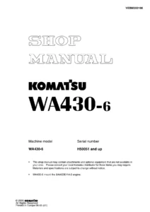
Komatsu WA430-6 Wheel Loader Shop Manual SEN00823-05 – Serial 65001 and Up
Original price was: $49.95.$29.95Current price is: $29.95.
Complete WA430-6 wheel loader shop manual coverage for serial numbers 65001 and up, including specifications, structure and function, standard values, testing and adjusting, troubleshooting, disassembly and assembly, and hydraulic/electrical diagrams. The specification section identifies the Komatsu SAA6D114E-3 diesel engine.
Description
Komatsu WA430-6 Wheel Loader Shop Manual SEN00823-05 – Serial 65001 and Up
The Komatsu WA430-6 Wheel Loader Shop Manual SEN00823-05 – Serial 65001 and Up brings together the workshop information for the WA430-6 wheel loader in one extensive technical reference. It covers the machine from specifications and component structure through testing, adjustment, troubleshooting, disassembly, assembly, and hydraulic and electrical diagrams. Coverage is identified for WA430-6 machines with serial numbers 65001 and up, and the specification section identifies the Komatsu SAA6D114E-3 diesel engine.
File Details
- Manual type: Shop Manual
- Brand / model: Komatsu WA430-6 wheel loader
- Serial number coverage: 65001 and up
- Engine identified: SAA6D114E-3
- Language: English
- Page count: 1678 pages
- File format: PDF
- Shop manual form number: SEN00823-05
Technical Information for Workshop Service
This WA430-6 shop manual is organized around the information needed to understand, test, diagnose, remove, install, disassemble, assemble, and adjust major machine systems. The specification material provides machine dimensions, weights, performance data, engine information, power-train details, hydraulic specifications, component weights, and fuel, coolant, lubricant, and capacity information. The structure and function material then traces how systems and components are arranged and how they operate, giving useful context before testing or dismantling work begins.
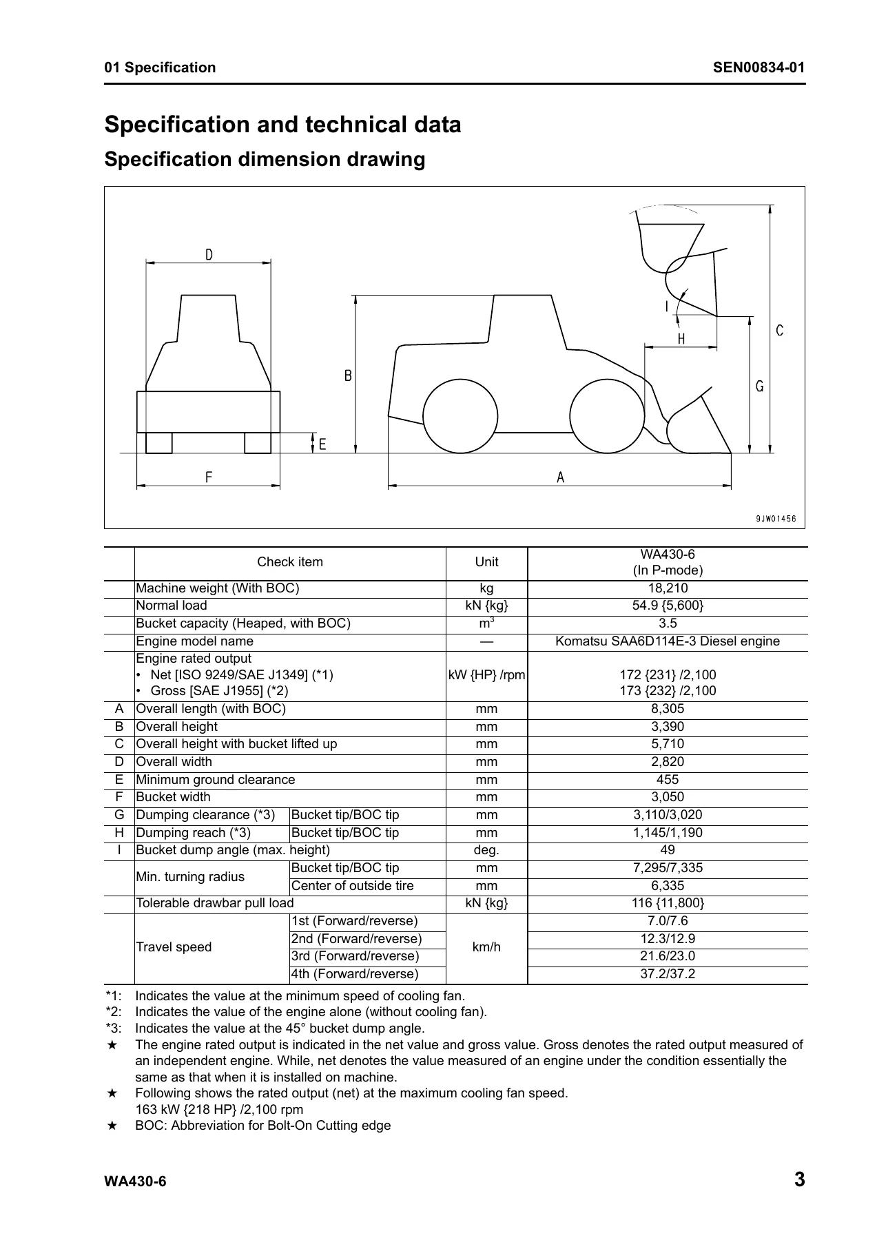
The specification section identifies a machine weight of 18,210 kg, a 3.5 m³ heaped bucket capacity, and the SAA6D114E-3 engine. Engine data includes the 4-cycle, water-cooled, in-line 6-cylinder direct-injection configuration with turbocharger and air-cooled aftercooler, together with bore, stroke, displacement, output, torque, idle-speed, starter, alternator, and battery data. Machine specification pages also cover dimensions, travel speeds, steering geometry, bucket positions, hydraulic pump delivery data, cylinder dimensions, system pressures, component weights, and fluid capacities.
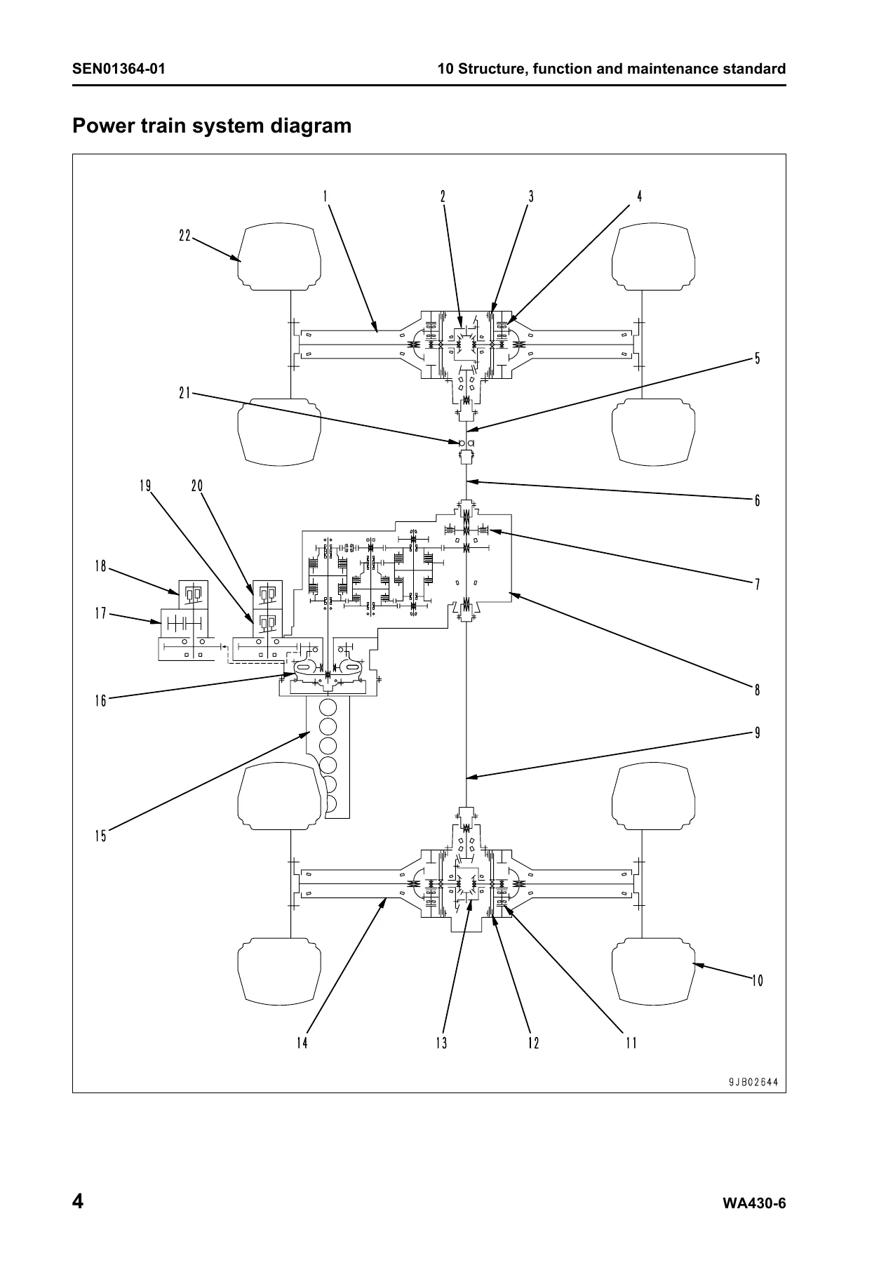
For power-train work, the manual follows the torque converter, transmission, shafts, axles, differentials, final drives, control valves, and ECMV operation. Steering coverage includes the pump, steering valve, orbit-roll valve, cylinders, stop and relief valves, and emergency steering equipment where equipped. Brake information covers the hydraulic brake circuit, valves, accumulator, wheel brakes, parking brake, and emergency release. Hydraulic coverage extends to pumps, control valves, CLSS, PPC components, accumulators, the hydraulic tank, work equipment circuits, bucket and boom functions, and hydraulic cylinders.
Electrical and electronic sections cover the machine monitor, transmission controller system, starting and stopping circuits, preheating, power-mode selection, derating and warm-up functions, parking-brake circuitry, sensors, and KOMTRAX-related information. The troubleshooting material is especially broad, combining a failure-code table with code-by-code diagnostic sections and separate electrical, hydraulic/mechanical, and engine troubleshooting modes. This makes the Komatsu WA430-6 shop manual useful both for symptom-led diagnosis and for following a displayed fault code into the relevant circuit or component checks.
Chapters Covered
- 00 Index and foreword
- Safety notice and basic workshop precautions
- How to read the shop manual and maintenance-standard terminology
- Handling electric equipment and hydraulic components
- Electric wire codes and circuit color codes
- Removal, installation, disassembly, and assembly precautions
- Push-pull type coupler procedures
- Standard tightening torque tables
- Conversion tables
- 01 Specification
- Specification dimension drawing and machine specifications
- Engine, power train, axle, tire, brake, and steering data
- Hydraulic pumps, valves, motors, and cylinder data
- Component weight table
- Fuel, coolant, lubricants, and capacities
- 10 Structure, function and maintenance standard
- Engine mounts, cooling system, cooling fan pump, and fan motor
- Power train, torque converter, transmission, ECMV, axles, differentials, and final drives
- Steering system, pump, valves, cylinders, and emergency steering
- Brake system, accumulator, wheel brakes, parking brake, and release system
- Undercarriage, axle mounting, center hinge pin, and tires
- Hydraulic system, pumps, tank, control valve, CLSS, PPC valve, and accumulators
- Work equipment linkage, bucket, positioner, boom kick-out, and cylinders
- Cab and air conditioner
- Machine monitor, transmission controller, KOMTRAX, sensors, and electrical circuits
- 20 Standard value table
- Standard service values for the engine
- Standard service values for the chassis
- 30 Testing and adjusting
- Tools for testing, adjusting, and troubleshooting
- Engine speed, exhaust, compression, blow-by, oil-pressure, and boost-pressure tests
- Valve-clearance adjustment and fuel-system pressure, leakage, return, and air-bleeding procedures
- Transmission controls, sensors, power-train oil pressure, and hydraulic-circuit flushing
- Steering-wheel, stop-valve, and steering-oil-pressure checks
- Hydraulic fan, service-brake, parking-brake, accumulator, and brake-pressure tests
- Work-equipment lever, PPC pressure, work-equipment pressure, bucket positioner, and boom kick-out checks
- Electrical troubleshooting preparation, diode checks, and KOMTRAX terminal operations
- Machine monitor adjustments, EMMS functions, and PM-clinic inspection information
- 40 Troubleshooting
- Failure-code table and fuse locations
- General troubleshooting methods and connector information
- Failure-code troubleshooting in Parts 1 through 10
- Electrical-system troubleshooting in E-mode
- Hydraulic and mechanical troubleshooting in H-mode
- Engine troubleshooting in S-mode
- 50 Disassembly and assembly
- General procedures, coating materials, and special tools
- Engine and cooling-system component removal and installation
- Torque converter, transmission, clutch pack, axle, and differential work
- Steering and brake component procedures
- Center hinge pin, counterweight, and frame-related procedures
- Hydraulic pumps, control valve, hydraulic tank, and work-equipment procedures
- Hydraulic-cylinder disassembly and assembly
- Cab, glass, seat, and air-conditioner unit procedures
- Engine controller and KOMTRAX terminal removal and installation
- 90 Diagrams and drawings
- Power-train hydraulic circuit diagram
- Hydraulic circuit diagram
- Electrical circuit diagrams
- Connector arrangement diagram
Taken as a whole, the manual connects component theory with measurable standards and hands-on workshop procedures. A technician can move from a system diagram or structure explanation to the relevant standard values, testing procedure, troubleshooting path, and then to removal or disassembly instructions when repair is required. The extensive failure-code and symptom-based sections are backed by circuit diagrams and connector information, while the disassembly material provides the sequence, precautions, special-tool references, tightening information, and service criteria needed for major component work.
Testing, Diagnosis, and Repair Coverage
The testing and adjusting chapters support systematic checks rather than trial-and-error replacement. Engine procedures include speed, exhaust color and temperature, compression pressure, blow-by pressure, engine oil pressure, boost pressure, and fuel-system checks. Power-train procedures include transmission adjustments, oil-pressure tests, hydraulic-circuit flushing, axle leakage checks, and drive-shaft inspection. Steering and brake procedures include pressure checks, linkage adjustments, performance tests, wear checks, air bleeding, and accumulator work. Work-equipment procedures cover control-lever checks, PPC and work-equipment oil pressures, residual-pressure release, bucket positioner adjustment, and boom kick-out adjustment.
Troubleshooting is divided so the reader can approach a problem from the information available on the machine. Failure-code sections address transmission, engine, controller, sensor, solenoid, monitor, and CAN communication faults. E-mode follows electrical symptoms such as starting, lighting, wiper, washer, horn, air-conditioner, KOMTRAX, transmission-mode, fan-reverse, ECSS, and indicator problems. H-mode covers travel, torque-converter, steering, brake, lift-arm, bucket, and work-equipment symptoms. S-mode covers engine starting, smoothness, power loss, smoke, oil and fuel consumption, oil pressure, overheating, abnormal noise, and vibration.
Disassembly, Assembly, and System Diagrams
Major workshop jobs are supported by dedicated removal, installation, disassembly, and assembly sections. These include the fuel supply pump, injectors, cylinder head, radiator, aftercooler, hydraulic oil cooler, engine assembly, seals, cooling fan components, fuel tank, torque converter, transmission, transmission clutch packs, parking brake, front and rear axles, differentials, steering demand valve, center hinge pin, counterweight, hydraulic pumps and tank, work equipment control valve, work equipment assembly, hydraulic cylinders, cab components, air-conditioner unit, engine controller, and KOMTRAX terminal.
The diagrams section completes the service workflow with hydraulic and electrical drawings. Power-train and machine hydraulic circuits help trace oil flow and component relationships, while the electrical circuit and connector arrangement drawings support circuit checks and fault isolation. Together with the structure drawings and sectional views found throughout the manual, these pages provide a visual reference for understanding component layout before testing or dismantling the machine.
Use the Komatsu WA430-6 Shop Manual for Confident Workshop Work
The Komatsu WA430-6 Wheel Loader Shop Manual SEN00823-05 – Serial 65001 and Up supports detailed service work ranging from routine testing and adjustment to fault diagnosis, component removal, transmission and hydraulic work, and major disassembly and assembly. Following the manual’s specified procedures, standard values, clearances, pressures, service limits, and tightening information helps keep repairs tied to the technical criteria provided for the WA430-6 instead of relying on guesswork. Your manual is delivered as an instant PDF after payment, with no shipping required; it can be viewed on compatible phones, tablets, and computers and printed when a paper reference is useful in the workshop.

Reviews
There are no reviews yet.