
Komatsu WA500-3LE Wheel Loader Chassis Shop Manual CEBM001202 – A70001 and Up
Original price was: $44.95.$26.95Current price is: $26.95.
Chassis shop manual for the Komatsu WA500-3LE wheel loader, serial A70001 and up. Covers specifications, structure and function, testing and adjustment, troubleshooting, disassembly and assembly, maintenance standards, hydraulic and power-train systems, steering, brakes, work equipment and electrical controls.
Description
Komatsu WA500-3LE Wheel Loader Chassis Shop Manual CEBM001202 – A70001 and Up
The Komatsu WA500-3LE Wheel Loader Chassis Shop Manual CEBM001202 – A70001 and Up is a detailed service-workshop reference for the WA500-3LE wheel loader in the stated serial range. It combines machine specifications and system explanations with testing, adjustment, troubleshooting, removal, installation, disassembly, assembly, and maintenance-standard information. The publication is centered on the chassis and machine systems, while the manual’s own publication information identifies separate engine publications for additional engine-specific service work.
File Details
- Manual type: Chassis Shop Manual
- Brand: Komatsu
- Model: WA500-3LE
- Machine serial numbers: A70001 and up
- Document number: CEBM001202
- Language: English
- Pages: 1046
- File format: PDF
Machine and Service Information
This WA500-3LE shop manual begins with the machine data needed to identify and evaluate the loader before repair work starts. The General section supplies dimension drawings, performance specifications, component weights, and fluid information. It includes data for general-purpose, excavating, and spade-nose rock bucket configurations, as well as tire-dependent dimensions. The specification pages identify the Cummins NTA14C diesel engine and provide power, torque, idle-speed, starting, charging, battery, power-train, axle, brake, steering, hydraulic, and work-equipment data used throughout chassis diagnosis and service.
Fluid and lubricant coverage is equally practical. The manual gives specified and refill quantities for the engine, torque converter and transmission group, hydraulic system, drive axles, fuel tank, and cooling system, followed by guidance for engine oil, transmission and hydraulic oil, axle oil, grease, diesel fuel, coolant, antifreeze concentration, and supplemental coolant additives. Standard torque requirements, coating materials, electric wire codes, conversion tables, and workshop safety instructions are also included near the front of the publication.
Chapters Covered
- 01 General
- Dimensions and specifications
- Weight table
- Fuel, coolant and lubricants
- Engine oil specifications
- Transmission, hydraulic and brake oil
- Axle oil, grease, diesel fuel and coolant specifications
- 10 Structure and Function
- Radiator and oil cooler; damper
- Torque converter, PTO, transmission and transmission control valve
- Power-train hydraulic circuit and ECMV
- Transfer, drive shafts, center support, axles, differential and final drive
- Center hinge pin, tires and wheels
- Steering piping, steering column, steering valve, Orbit-roll valve and diverter valve
- Brake circuit, brake valves, charge valve, accumulator, slack adjuster and parking brake
- Hydraulic circuit system, hydraulic tank, PPC valve, cut-off valve and main control valve
- Work-equipment linkage, bucket, bucket positioner and boom kick-out
- Cab, ROPS canopy and air conditioner
- Electric circuit diagrams and machine monitor system
- All-range electronic control automatic transmission system, transmission controller and sensors
- Engine starting, engine stop, ether start, electric transmission control, kick-down and electric parking-brake control circuits
- 20 Testing, Adjusting, and Troubleshooting
- Testing and adjustment procedures for machine systems
- Engine-related checks with references to the pertinent engine manual where required
- Torque converter and transmission pressure checks
- Steering oil-pressure testing and adjustment
- Hydraulic and work-equipment checks
- Bucket positioner and boom kick-out adjustment
- Transmission controller learning and main-monitor adjustment
- Troubleshooting preparation, connector handling and troubleshooting-chart methods
- Transmission controller, main monitor, maintenance monitor, electrical, hydraulic and mechanical troubleshooting
- ECSS and joystick-steering control-system troubleshooting information where applicable
- 30 Disassembly and Assembly
- Repair-operation precautions, special tool list and special-tool sketches
- Starting motor, alternator, cooling and selected engine-mounted component removal and installation
- Radiator and damper
- Torque converter, transmission, transfer and parking brake
- Transmission control valve and ECMV
- Drive shaft, center support, front and rear axles, differentials and final drives
- Orbit-roll valve, steering cylinders and steering valve
- Brake valve, slack adjuster and front/rear brake assemblies
- Hydraulic pumps, hydraulic tank and hydraulic filter
- PPC valve and main control valve
- Boom and bucket cylinders
- Center hinge pin and work equipment
- Bulkhead, floor frame, counterweight and fuel tank
- Cab and air-conditioner components
- 40 Maintenance Standard
- Engine and transmission mounts
- Torque converter charging pump, damper, torque converter and PTO
- Transmission, transfer and relief valves
- Drive shaft, center support, differential, final drive and axle mount
- Center hinge pin, steering column, steering pump, steering valve and steering-cylinder mount
- Brake valve, slack adjuster, service brake and parking brake
- Hydraulic pump, switch/PPC pump, PPC valve, cut-off valve and main control valve
- Hydraulic cylinders, bucket linkage and bucket
- Bucket positioner, boom kick-out and ROPS cab
- 90 Other
Taken together, these chapters move from understanding how the WA500-3LE systems are built and how they work, through measurement and fault isolation, into component removal and overhaul, and finally into inspection criteria for deciding whether parts remain within service limits. That progression makes the manual useful both for diagnosing a symptom before dismantling and for checking components accurately during repair.
Power Train, Steering, Brakes and Hydraulics
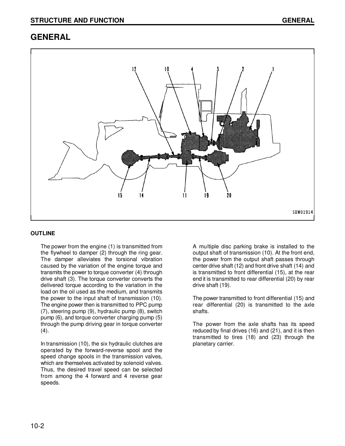
A large portion of the Komatsu WA500-3LE Wheel Loader Chassis Shop Manual CEBM001202 – A70001 and Up is devoted to the power train. Illustrated sections trace power flow through the damper, torque converter, planetary transmission, transfer, drive shafts, differentials and final drives. Transmission pages explain the 4-forward and 4-reverse speed arrangement, clutch combinations, ECMV operation, relief circuits and lubrication. Testing material then provides procedures for checking main relief pressure, torque-converter pressures and individual clutch pressures, while the disassembly section covers transmission, torque converter, transfer and associated components in service sequence.
Steering information follows the fully hydraulic articulated system from the steering pump and Orbit-roll valve through the steering valve, stop valve, diverter valve and steering cylinders. The manual explains normal steering operation as well as the ground-driven steering arrangement used if engine or pump power is lost while traveling. Brake coverage includes piping and circuit diagrams, left and right brake valves, charge valve, accumulators, slack adjusters, wet multiple-disc wheel brakes, the transmission-mounted parking brake, and emergency parking-brake release arrangements.
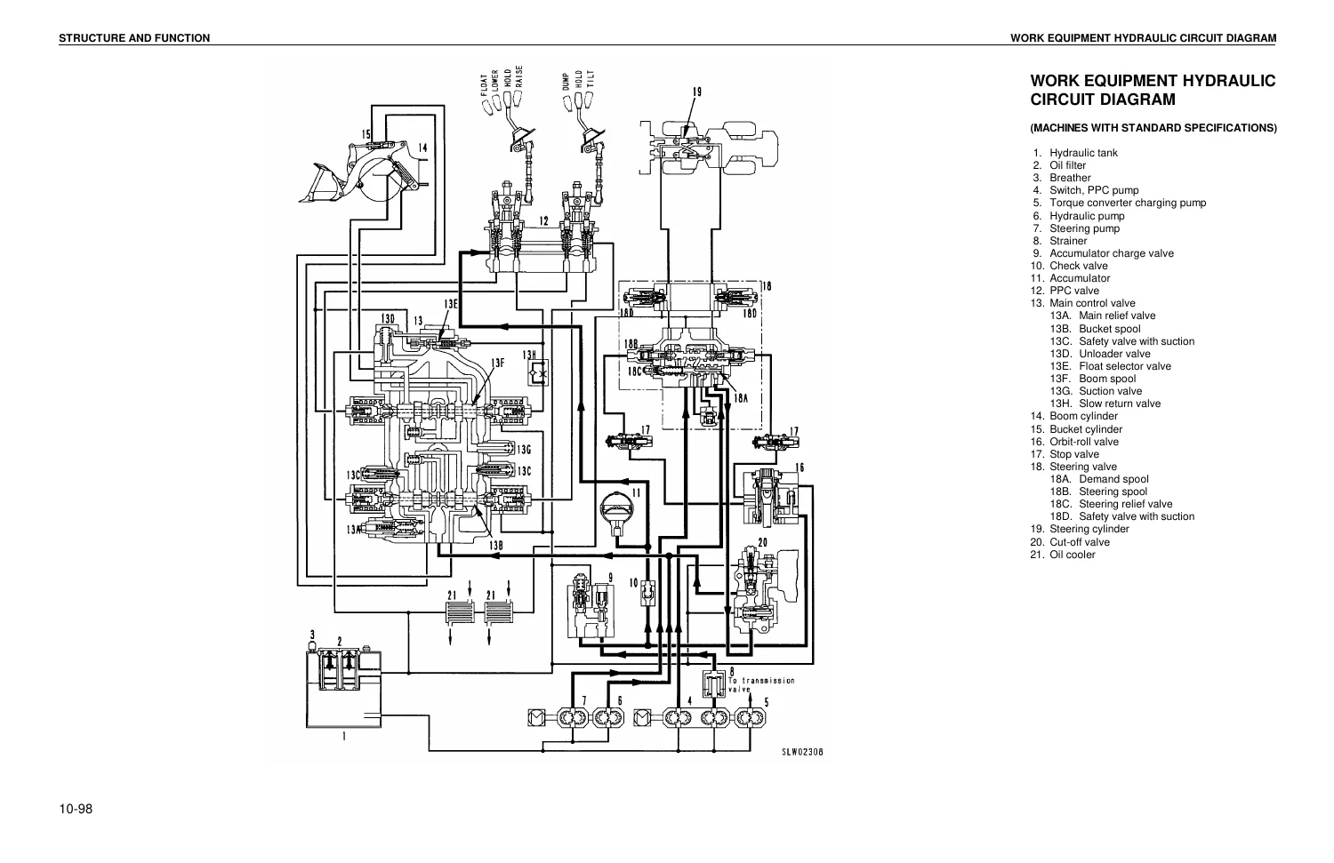
The hydraulic chapters connect the work-equipment and steering circuits with clear system diagrams. They show the hydraulic tank, pumps, PPC controls, main control valve, boom and bucket cylinders, relief and suction valves, cut-off functions, and oil cooler. Boom RAISE, LOWER and FLOAT operation and bucket DUMP and TILT operation are described at valve level, so a technician can follow pressure-oil paths instead of relying only on component location. This is particularly useful when a symptom could originate in the pilot circuit, main valve, cylinder circuit, or pressure-control hardware.
Testing, Fault Finding and Repair Procedures
The testing and adjusting material turns the system explanations into measurable checks. Procedures cover pressures, clearances, control settings, monitor adjustments and other service values, with safety conditions and preparation steps included where required. The troubleshooting portion explains how to use judgement charts, error and action codes, connectors, pin tables and system-specific fault paths. The manual groups troubleshooting by systems such as the transmission controller, main and maintenance monitors, electrical circuits, and hydraulic/mechanical systems, helping the technician move from a reported problem toward a cause and remedy.
For hands-on repair, the disassembly and assembly chapter is extensive. It covers safe preparation, hose and wiring identification, lifting precautions, special tools, specified tightening practices and air bleeding after hydraulic work. Procedures extend across major chassis assemblies including the transmission, axles, differentials, final drives, steering components, brakes, pumps, hydraulic tank, control valves, cylinders, center hinge, work equipment, cab and air-conditioning hardware. Component weights and hoisting guidance elsewhere in the manual support planning for larger removals.
Inspection Standards for Reassembly Decisions
The Maintenance Standard section is more than a summary of the repair chapter. It provides the dimensional and performance criteria used when inspecting disassembled parts. Entries include standard sizes, tolerances, clearances, repair limits, spring dimensions and loads, pump discharge values, wear limits, and adjustment criteria for many chassis systems. These values help determine whether a component can be reused, requires adjustment, or should be replaced before the machine is returned to service.
Examples span the transmission and power train, differential and final drive, center hinge, steering components, brake and parking-brake parts, hydraulic pumps and valves, cylinders, bucket linkage, bucket wear points, and positioner/kick-out settings. Having these inspection standards alongside the structure, test and overhaul sections reduces the need to work from memory when judging wear during a repair.
Important Coverage Note
This publication is identified as the chassis shop manual for the WA500-3LE. The manual itself explains that Komatsu shop information is divided among chassis, engine, electrical and attachment volumes to avoid duplication, and its publication list identifies separate engine shop and troubleshooting publications. Although this PDF contains engine specifications, engine-related checks and removal/installation coverage for selected components, some engine procedures explicitly direct the technician to the pertinent engine manual. Buyers planning complete engine-internal repair should therefore use the appropriate engine publication together with this chassis manual.
Service the WA500-3LE With the Correct Chassis Reference
The Komatsu WA500-3LE Wheel Loader Chassis Shop Manual CEBM001202 – A70001 and Up supports systematic diagnosis, adjustment, chassis repair, component removal and installation, overhaul work, and service-limit inspection across the loader’s power train, steering, brake, hydraulic, work-equipment and electrical-control systems. Correct procedures, pressure checks, tightening values, clearances and inspection limits matter when a repair must be completed safely and returned to service with the right settings. The manual is delivered as an instant PDF after payment, with no shipping delay; it can be viewed on compatible computers, tablets and phones and printed for workshop use.

Reviews
There are no reviews yet.