Description
Kongsberg Aquapilot AzT US205 FP Azimuth Thruster Control System User Guide 514-U374
This Kongsberg Aquapilot AzT US205 FP Azimuth Thruster Control System User Guide is the practical operating reference for the Aquapilot control system used with Kongsberg azimuth thrusters. Work number 514-U374, serial numbers U374A and U374B, it covers the control units, operating modes, alarm handling and safety information needed by bridge and engine room personnel working with US, UL, ULE, UUC and Contaz thruster models.
File Details
- Manual type: User’s Guide
- Brand: Kongsberg
- Product: Azimuth Thruster
- Product model: US, UL, ULE, UUC and Contaz
- Technical name: Control system
- Work number: 514-U374
- Serial numbers: U374A, U374B
- Language: English
- Page count: 115
- File format: PDF
- Revision date: 29.11.2021
Chapters Covered
- 1. General Information: Contents of the user’s guide, Terminology
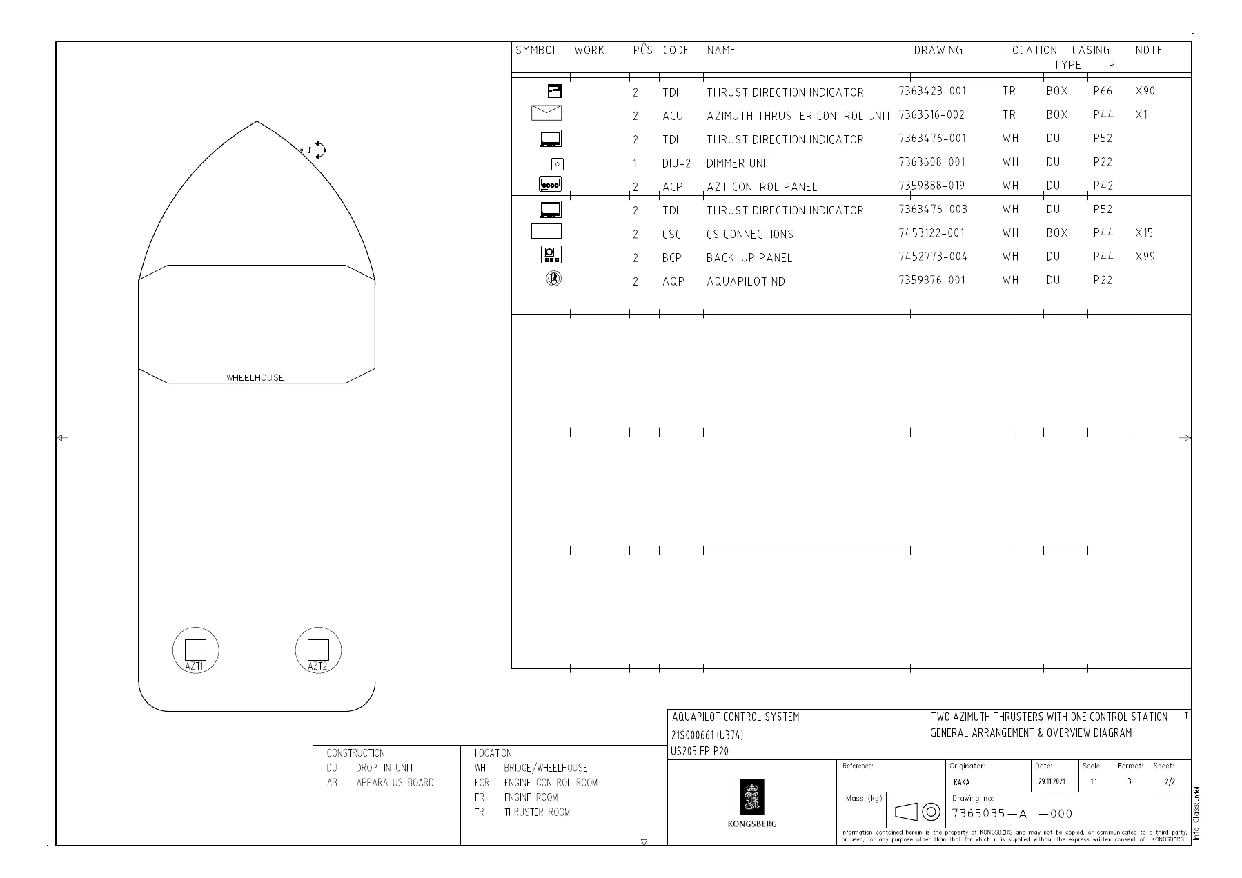
- 2. Control System and Modes: Aquapilot for AZT with FPP and with clutch HyTu, Azimuth thruster interface to autopilot, General arrangement + Overview diagram
- 3. Control Units and Functions: Aquapilot control lever for FPP, Maintenance control switch AMS08, Azimuth thruster control panel FP, Back-up control, Thrust direction and speed indication
- 4. Operation: Steering the ship, two Azimuth thruster stern, Operation restrictions for thrusters
- 5. Alarm and Failure Indications: Trouble shooting, Description of alarms, Serial link I/O units alarm indications, HHT Terminal software user’s guide
- 6. Safety Information: Safety information
- Additional included documentation: HHT Terminal Software user’s guide and DEIF XDi indicator operation instructions
Across these chapters the guide explains how the Aquapilot system turns and controls azimuth thrusters, how the single-lever control head manages steering and thrust, how operational modes such as autopilot, tandem, crawling and DP are selected, and how back-up, ECR, maintenance and local control options are used. It also documents the alarm and failure indications that appear on the control panel and serial link I/O units, with troubleshooting steps for steering, pitch, clutch, RPM, supply voltage and communication faults. The safety section sets out signal word definitions and general precautions for working with azimuth thruster propulsion units.
Key Systems and Functions Covered
- Aquapilot control system for azimuth thrusters with FP propellers and clutch
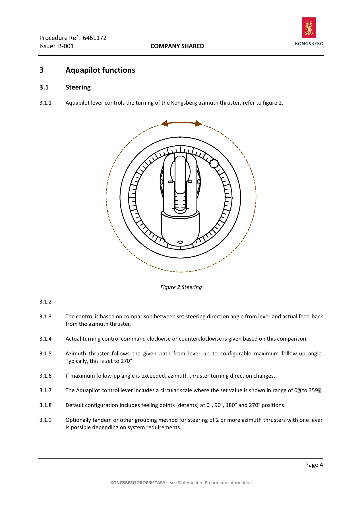
- Continuous 360-degree steering control and RPM/thrust control from the Aquapilot lever
- Clutch engage and disengage logic, including prevention of inadvertent disengagement
- Autopilot mode interface with angle set values and control signal range
- Back-up control panel, ECR control, maintenance control and local control
- Thrust direction indicator and speed indication
- Alarm descriptions for ACU, steering, pitch, clutch, RPM, supply voltage and bus faults
- HHT Terminal Software for CanMan control system, including Ethernet connection, log and dump retrieval, signal viewing and calibration
- DEIF XDi indicator menus, dimming, day/night colour, warning log and setup
Operational Modes and Controls
The manual details how the Aquapilot control head combines steering and thrust into one lever. Steering uses continuous 360-degree movement, while thrust is controlled by tilting the lever through a 90-degree range. Feeling points, clutch disengage prevention, motorized synchronization for multiple control stations and touch alarm functions are all described. Operational modes include autopilot, tandem, crawling and DP, with notes on how each mode is selected and what control remains with the Aquapilot lever or transfers to the autopilot or DP system.
Complete PDF Bookmark Tree
Complete Bookmarks
The complete bookmarks in the “Kongsberg Aquapilot AzT US205 FP Azimuth Thruster Control System User Guide 514-U374” are as follows:
+6470801-A-332p. 1
Aquapilot Control Systemp. 1
LIST OF HEADINGSp. 3
LIST OF DRAWINGSp. 4
TABLE OF CONTENTSp. 5
1. GENERAL INFORMATIONp. 7
2. CONTROL SYSTEM AND MODESp. 13
3. CONTROL UNITS AND FUNCTIONSp. 22
4. OPERATIONp. 55
5. ALARM AND FAILURE INDICATIONSp. 68
6. SAFETY INFORMATIONp. 114
+6461386-B-000p. 7
Descriptionp. 8
1 Generalp. 8
2 Developmentp. 8
3 Specifications of Equipment Deliveredp. 8
4 Supplementary manualsp. 8
+6461005-D-000p. 9
Descriptionp. 10
1 Abbreviationsp. 10
+6461231-B-000p. 13
Descriptionp. 14
+1 Generalp. 14
1.1 Aquapilot Control System for Azimuth Thrusterp. 14
+1.2 Aquapilot Control System Functionalityp. 14
1.2.7 Steering Controlp. 14
1.2.8 RPM Controlp. 14
1.2.9 Clutch Controlp. 14
1.2.10 Retractable UL-Thrusters (Optional)p. 15
1.2.11 Clutch Control on UL-Thrustersp. 15
+2 Operation of Azimuth Thruster and Control Modesp. 15
+2.1 Operational Modesp. 15
2.1.1 Autopilot Mode (Optional Function)p. 15
2.1.2 Tandem Mode (Optional Function)p. 15
2.1.3 Crawling Mode (Optional Function)p. 15
2.1.4 DP Mode (Optional Function)p. 15
3 Back-up control (Optional)p. 15
4 ECR control (Optional)p. 16
5 Maintenance control (Optional)p. 16
6 Local Control (Optional)p. 16
7 Stand-By Hydraulics (Optional)p. 16
+6461135-B-003p. 18
Descriptionp. 19
1 Autopilot Modep. 19
2 Azimuth Thruster -> Autopilotp. 19
3 Autopilot -> Azimuth Thrusterp. 19
7365035-A-000p. 20
+6461172-B-001p. 22
Descriptionp. 23
+1 Control Lever Design Principlesp. 23
1.1 Human Engineeringp. 23
1.2 Continuous 360 Steeringp. 23
1.3 Designed for the Masterp. 23
1.4 Ergonomic Design and Shapep. 23
+2 Aquapilot ND Control Lever Functionalityp. 24
2.1 Combined Controlp. 24
2.2 Operation Logicp. 24
2.3 Feeling Pointsp. 24
2.4 Clutch Disengage Preventionp. 24
2.5 Motorized Operationp. 24
2.6 Touch alarmp. 24
2.7 Redundancyp. 24
2.8 Maintenance and Servicep. 24
+3 Aquapilot functionsp. 25
4 Thrustp. 26
+6455775-C-002p. 27
Descriptionp. 28
1 Generalp. 28
2 Use of AMS08p. 28
+6461457-B-001p. 29
Descriptionp. 30
+1 Generalp. 30
1.3 Indications Symbolsp. 30
6461138-C-004p. 34
+6470289-C-001p. 35
+1. General Descriptionp. 37
1.1. New Technologyp. 37
1.2. Compatibility With Earlier Systemp. 37
1.3. Rolls-Royce Specific Functionalityp. 37
+2. Products And Variantsp. 38
2.1. Product Rangep. 38
2.2. Utilisation of XDi in Rolls-Royce Marine Applicationsp. 38
+3. Operation Instructionsp. 39
3.1. Controlling Display IIlumination Levelp. 39
3.2. Dimmer Potentiometer Panelp. 39
3.3. Buttonsp. 40
3.4. Accessing XDi Menusp. 40
3.5. Menu Structurep. 41
3.6. Setup Wizardp. 41
3.7. Surveyor Infop. 42
+3.8. Master Resetp. 43
3.8.1. Factory resetp. 43
3.8.2. Reset As Service Unitp. 43
+3.9. User Menup. 44
3.9.1. User Menu – “Fixed dimmer level”p. 44
3.9.2. User Menu – “Dimmer group”p. 45
3.9.3. User Menu – “Dimmer setup”p. 46
3.9.4. User Menu – “Day/night colour”p. 48
3.9.5. User Menu – “Warning and sound”p. 49
3.9.6. User Menu – “Rotate display”p. 51
4. Note On Lifetime And Backlight Intensityp. 52
+5. Trouble Shootingp. 53
5.1. Typical Error Conditionsp. 53
5.2. Azimuth Feedback Not Availablep. 53
5.3. Pitch Feedback Not Availablep. 53
5.4. Propeller Or Maine Engine RPMp. 53
6. Propeller RPM Bar Linearityp. 54
7. Referencesp. 54
+6452400-E-002p. 55
Descriptionp. 57
1 The symbol of steering diagramsp. 57
+2 Position keepingp. 57
2.1 Position keeping with small powerp. 57
2.2 Position keeping with small powerp. 57
2.3 Basic starting and position keepingp. 58
+3 Aheadp. 58
3.1 Straight aheadp. 58
3.2 Turn port sidep. 58
3.3 Port side turn, minimum streamp. 58
3.4 Turn starboardp. 59
3.5 Starboard turn, minimum streamp. 59
+4 Asternp. 60
4.1 Straight asternp. 60
4.2 Turn port sidep. 60
4.3 Turn starboardp. 60
+5 Turn around the spotp. 61
5.1 Turn port sidep. 61
5.2 Turn starboardp. 61
+6 Side stepp. 61
6.1 Slow side stepp. 61
6.2 Fast side stepp. 61
6.3 Slow side stepp. 62
6.4 Fast side stepp. 62
+7 From ahead to astern (fast stop, crash stop)p. 62
7.4 Astern from ahead, fast stopp. 63
7.5 Astern from ahead, no washp. 63
8 Propeller wash and environmental sensitive areasp. 63
+6454067-O-000p. 64
Descriptionp. 65
1 Generalp. 65
2 Windmillingp. 65
3 Restrictions in use of backstop device (if mounted)p. 65
+4 Restrictions for UL and ULE-thrustersp. 65
4.1 Access to UL and ULE operating spacep. 65
4.2 Transit operation in the lowered positionp. 66
4.3 Raising or lowering when the vessel movesp. 66
4.4 Raising or lowering when the vessel is in dry dockp. 66
4.5 Ice conditionp. 66
5 If thrusters blow against each otherp. 66
6 Thruster intermediate shaft alignment when unit is exchangedp. 66
7 Starting the thruster during the ship is in motionp. 66
8 Spray lubricated units (ARC, UUC 505 and Contaz 50)p. 66
6451657-D-000p. 68
6461146-D-000p. 70
+6454742-D-000p. 75
Descriptionp. 76
1 Running indicationp. 76
2 CAN bus indicationp. 76
3 Alarm indicationsp. 76
+6471708-D-001p. 77
+1. Generalp. 80
1.1. The HHT terminal software (HHTTS)p. 80
1.2. Installing HHTTSp. 81
1.3. Uninstalling HHTTSp. 82
+1.4. Connecting PC to Ethernet LAN service RJ45 portp. 82
1.4.1. X15 Interface unit at bridgep. 82
1.4.2. Local LAN switch in ACUp. 83
1.4.3. Controllers CCN02, CCN11 and CCN14 (if used)p. 83
1.5. Power on sequence of controllers with HHTTSp. 84
1.6. Activating connectionp. 85
1.7. Connection statep. 86
1.8. Application detailsp. 87
+2. HHTTS functionsp. 88
2.1. Terminal windowp. 88
2.2. Keyboard and mousep. 89
+2.3. Preferencesp. 89
2.3.1. General settingsp. 89
2.3.2. Folder settingsp. 91
2.3.3. Communications settingsp. 92
2.4. Search IP addressesp. 93
2.5. Help functionp. 94
2.6. About IP addressesp. 94
2.7. Receiving logp. 95
2.8. Receiving dumpp. 98
2.9. Software updatesp. 99
2.10. Software versionp. 99
2.11. Feedback and supportp. 100
+3. HHT interface commandsp. 101
3.1. Keyboard keysp. 101
3.2. Password queryp. 101
+4. HHT interface main menup. 101
4.1. Exitp. 101
4.2. Exit remotep. 101
4.3. Freep. 102
4.4. Watchp. 102
4.5. Dumpp. 102
+4.6. I/Op. 102
4.6.1. Calibration, Viewp. 102
4.6.2. Calibration of an analog input channelp. 102
4.6.3. Calibration of an analog output channelp. 103
4.6.4. Calibration of a digital input or output channelp. 104
+4.7. Num. I/Op. 105
4.7.1. Numeric calibration of a digital I/O channelp. 105
4.7.2. Numeric calibration of an analog I/O channelp. 105
4.8. Logp. 105
4.9. Timep. 106
4.10. Parametersp. 107
+4.11. Signalsp. 107
4.11.1. Select process / signal, viewp. 107
4.11.2. Simulationp. 107
4.11.3. Updating parametersp. 108
4.11.4. Updating tables (function curves and ramp delays)p. 108
4.12. Configp. 110
+4.13. Bus signalsp. 111
4.13.1. Select bus signal, Viewp. 111
4.13.2. Updating bus signal IDp. 111
4.14. Remote nodep. 111
4.15. Versionp. 112
4.16. CMSPp. 112
4.17. Serial portsp. 112
4.18. Ethernetp. 112
+5. Finding faults from CanMan systemp. 112
5.1. Categoriesp. 112
5.2. First point of inspection, the logp. 113
5.3. Second point of inspection, signalsp. 113
+6456930-A-000p. 114
Referencesp. 114
Descriptionp. 115
1 Safety Informationp. 115
Safety and Alarm Handling
Safety information uses Note, Caution, Warning and Danger signal words. The alarm chapters list high-level failures and low-level warnings, explaining operating capability and how to clear each condition. Troubleshooting guidance starts with identifying whether the fault is mechanical, electric, electronic, hydraulic, lubrication or external, then checking circuit breakers, switches, fuses and supply voltages. Specific alarm tables cover ACU failure, steering angle sensor failure, pitch feedback failure, clutch response failure, RPM command failure, bus failures, overload alarms and panel warnings.
Who This Manual Is For
This Kongsberg Aquapilot AzT US205 FP user guide is written for operators, bridge officers, engine room personnel and service technicians who need to understand the Aquapilot control system on vessels equipped with US, UL, ULE, UUC or Contaz azimuth thrusters. It assumes general technical knowledge and vessel operation experience, and it supplements the more detailed Aquamaster Propulsion Unit Service Manual and Aquapilot Control System Service Manual.
Order Your Copy
With this Kongsberg Aquapilot AzT US205 FP Azimuth Thruster Control System User Guide 514-U374, you can operate and troubleshoot the Aquapilot control system with correct procedures, understand alarm meanings, and follow the documented control modes for safe manoeuvring. The guide supports steering and thrust control checks, clutch and RPM operations, back-up control selection, autopilot interface checks, and alarm response. It matters because azimuth thruster control involves precise angle and thrust commands where incorrect actions can affect vessel safety. Delivery is instant as a PDF download after payment, readable on any device, and printable for bridge or workshop use.

Reviews
There are no reviews yet.