
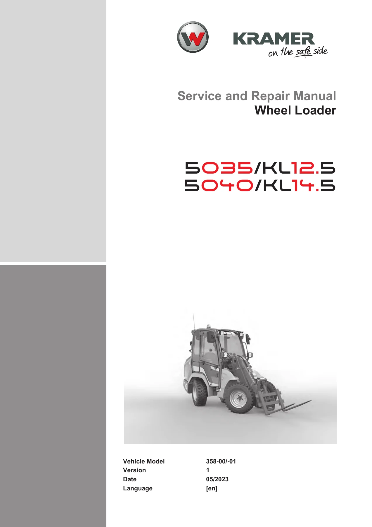
Kramer Wheel Loader 5035 KL12.5 & 5040 KL14.5 Service and Repair Manual (358-00/-01)
Original price was: $39.95.$24.95Current price is: $24.95.
Complete 473-page Kramer service and repair manual for the 5035/KL12.5 (type 358-00) and 5040/KL14.5 (type 358-01) wheel loaders, covering engine, drive, axles, hydraulics, steering, brakes, cab and maintenance procedures.
Description
Kramer Wheel Loader 5035 KL12.5 & 5040 KL14.5 Service and Repair Manual
This is the full Kramer- Werke service and repair documentation for the SO35/KL12.5 and SO40/KL14.5 wheel loaders, published under document number 358-00/-01, version 1. It is the same manual issued for the two machine variants — type 358-00 (5035 / KL12.5, 19 kW diesel) and type 358-01 (5040 / KL14.5, 28 kW diesel) — and it is written for technicians who need to remove, disassemble, inspect, reassemble and adjust the major assemblies of these compact loaders.
File Details
- Manual type: Service and Repair Manual (SRM)
- Brand / manufacturer: Kramer- Werke GmbH
- Models covered: SO35/KL12.5 (type 358-00), SO40/KL14.5 (type 358-01)
- Document number: 358-00/-01
- Version: 1
- Language: English
- Page count: 473
- File format: PDF
- Publisher address: Wacker Neuson Straße 1, 88630 Pfullendorf, Germany
- Copyright: 2023, Kramer- Werke GmbH
Chapters Covered
- Introduction
- Notes on the repair manual
- Safety instructions
- Symbols, abbreviations, conversions
- Tightening torques
- Maintenance
- Maintenance preparation and notes
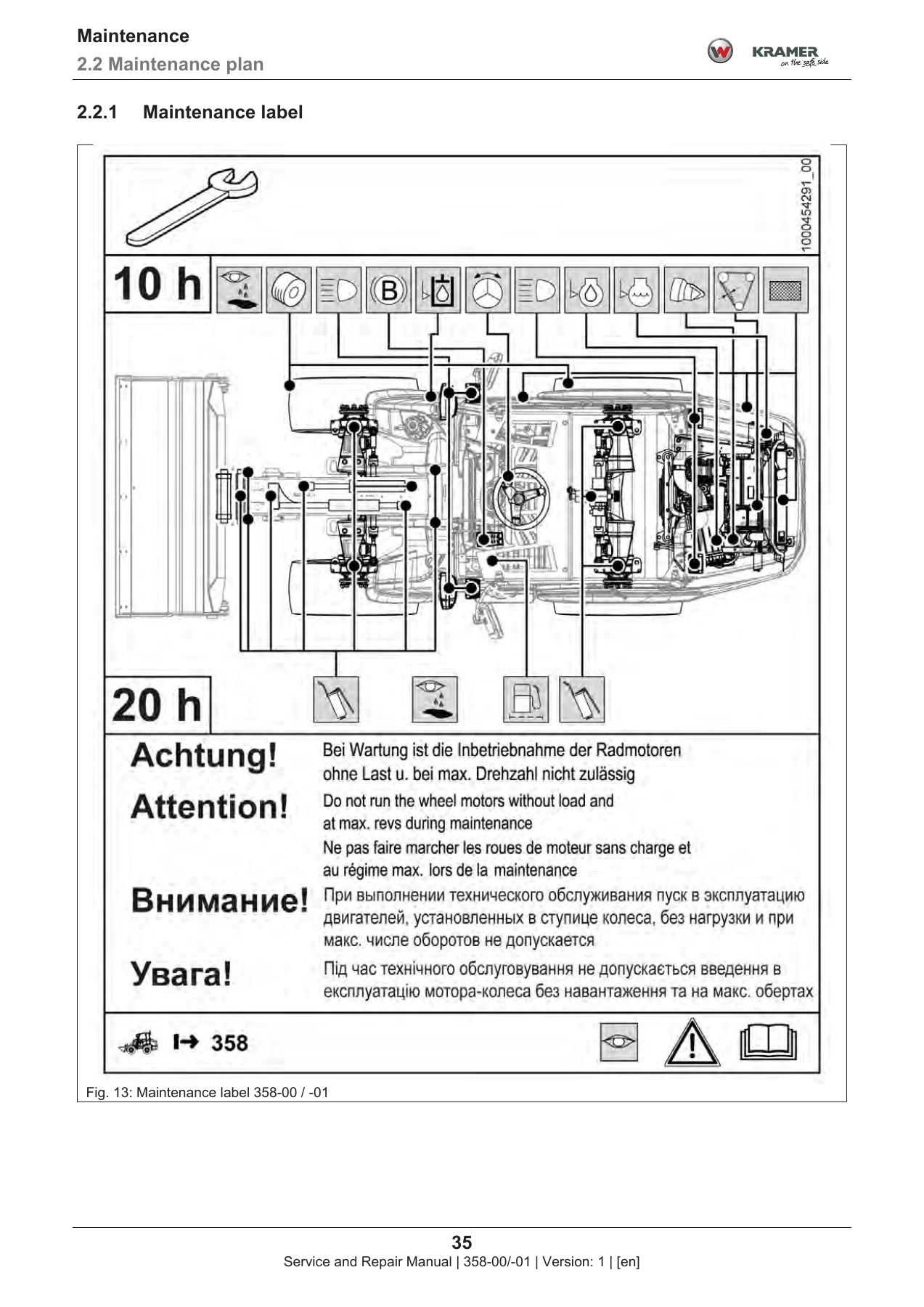
- Maintenance plan
- Fluids and lubricants
- Maintenance accesses
- Cleaning and maintenance work
- Lubrication work
- Fuel system
- Engine lubrication oil system
- Cooling system
- Air filter
- Exhaust gas after-treatment
- Hydraulic system
- Braking system
- Electrical system
- Heating, ventilation, air conditioning system
- Pressure accumulators
- V-belts and flat belts
- Hitch
- Tires
- Washer system
- Attachments
- Vehicle conservation
- Engine
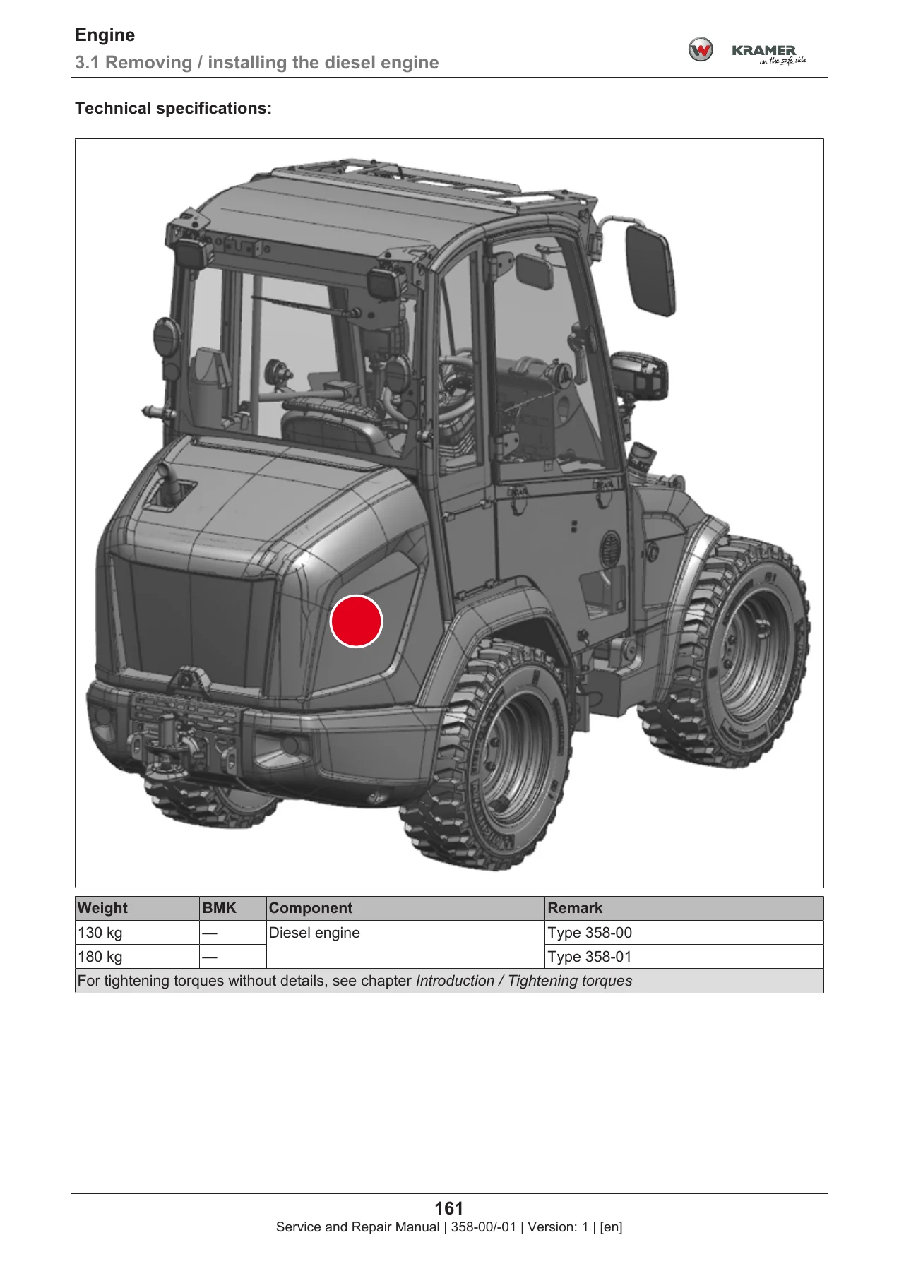
- Removing / installing the diesel engine
- Removing / installing the coupling
- Removing / installing the starter
- Removing / installing the alternator
- Removing / installing the air filter
- Removing / installing the fuel tank
- Removing / installing the fuel gage
- Removing / installing the fuel pre-filter console
- Removing / installing the fuel filter console
- Removing / installing the fuel feed pump
- Removing / installing the stopping solenoid
- Removing / installing the pressure switch for engine oil
- Removing / installing the accelerator pedal
- Removing / installing the throttle cable
- Removing / installing the manual accelerator
- Removing / installing the exhaust silencer
- Removing / installing the DOC/DPF
- Cooling
- Removing / installing the oil/water radiator
- Drive system
- Removing / installing the drive pump
- Removing / installing the wheel motor
- Removing / installing the distribution block
- Axles
- Removing / installing the front axle
- Removing / installing the rear axle
- Brake
- Removing / installing the inching pedal
- Steering
- Removing / installing the steering column
- Removing / installing the steering orbitrol
- Removing / installing the steering mode valve
- Hydraulics
- Removing / installing the hydraulic oil tank
- Removing / installing the operating pump
- Removing / installing the main control block
- Trims
- Removing / installing the engine hood
- Removing / installing the ballast weight
- Removing / installing the wheel guard
- Removing / installing the inner side trim
- Removing / installing the inner front trim
- Cab
- Removing / installing cab bearings
- Removing / installing the driver’s seat
- Heating/air conditioning system
- Removing / installing the heating unit
- Removing / installing the blower
Taken as a whole, this Kramer wheel loader service and repair manual is a complete workshop reference, not a single-task repair sheet. It moves from daily and periodic maintenance (fluid specifications and fill quantities, lubrication points, filter replacement, tightening torques for standard fasteners and hydraulic fittings) into full component-level removal and installation procedures for the diesel engine, coupling, starter, alternator, cooling package, hydrostatic drive pump and wheel motors, axles, steering components, hydraulic oil tank, operating pump and main control block, plus the cab, trims and HVAC system. Every procedure is tied to torque values, safety supports, fluid capacities and check measurements, so a technician can pull a single assembly, do the job, and put the machine back into service without guessing at the numbers.
Coverage in Detail
The 5035/KL12.5 (type 358-00) uses the 19 kW diesel engine variant, while the 5040/KL14.5 (type 358-01) uses the 28 kW engine. Where the two variants diverge — engine removal, radiator removal, air filter removal, fuel pre-filter and fuel filter console removal, DOC/DPF service, exhaust silencer, throttle cable, stopping solenoid, and the air conditioning compressor mount — the manual splits the procedure and labels the steps by type, so you always know which machine you are working on. Shared systems (hydraulics, axles, brakes, steering, cab, trims, HVAC) are documented once with the variant-specific exceptions called out where they occur.
What You Can Do With This Manual
- Pull and reinstall the diesel engine, coupling, starter and alternator with the correct torque values and screw-lock points.
- Service the fuel system end to end — tank, gage, pre-filter console, filter console, feed pump, stopping solenoid, bleeding procedure.
- Remove and install the oil/water radiator, drain and refill coolant, and clean the radiator fins.
- Remove and install the hydrostatic drive pump, wheel motors and distribution block, including the vacuum-pump and oil-fill steps.
- Remove and install front and rear axles, steering cylinder and tie rod head settings.
- Replace hydraulic oil, breather filter and return filter; check hydraulic oil level.
- Remove and install the main control block, operating pump and hydraulic oil tank.
- Perform the full periodic maintenance plan, from daily checks to the 1500-hour (annual) Inspection “C”.
- Look up tightening torques, fluid capacities, tire and pressure accumulator data, and belt tension values.
Why This Matters
The 5035 and 5040 wheel loaders are compact machines with tight assemblies and safety-relevant systems — a raised loading system that must be secured on the lifting cylinder before any work beneath it, pressure accumulators filled only with nitrogen, high-pressure hydraulic lines, brake plates inside the wheel motors, and a cooling system under pressure when hot. Working from the correct Kramer procedure and the correct torque value is the difference between a clean repair and a repeat failure or an injury. This manual exists to give that procedure and those values in one place, matching the machine you actually have in the yard.
Delivery
IMAGES PREVIEW
The manual is delivered as an instant PDF download — no shipping, no waiting. Open it on a laptop, tablet or phone in the workshop, or print the pages you need for the job at hand. Once payment is confirmed, the file is available immediately.

Reviews
There are no reviews yet.