

KTM 990 Supermoto R 2011 Repair Manual – Complete LC8 Workshop PDF
Original price was: $52.95.$34.95Current price is: $34.95.
Full KTM 990 Supermoto R repair manual for the 2011 model year, covering EU, FR, AUS/UK and USA variants. Engine strip-down, fork and shock absorber servicing, brake and clutch overhaul, wiring diagrams, torque tables and special tools — all in one searchable workshop PDF.
Description
KTM 990 Supermoto R Repair Manual — Article 3206108en
This is the complete KTM 990 Supermoto R repair manual, published under article number 3206108en and written for the 2011 model year across the EU, FR, AUS/UK and USA market versions. It is a genuine full-length workshop document, not a trimmed owner’s booklet. The coverage runs from something as simple as bleeding the fork legs through to splitting the engine cases, pulling the crankshaft and measuring main bearing shells. Every torque figure, wear limit and adjustment value sits inside the procedure it belongs to, so you are working from the same numbers a KTM workshop would use.
File Details
- Manual type: Repair manual (workshop service manual)
- Brand: KTM
- Models covered: 990 Supermoto R EU, 990 Supermoto R FR, 990 Supermoto R AUS/UK, 990 Supermoto R USA
- Engine family: LC8
- Language: English
- Page count: 291
- File format: PDF
- Article number: 3206108en
- Publication year: 2011
Chapters Covered
- Means of Representation
- Safety Advice
- Important Information
- Serial Numbers
- Motorcycle
- Fork, Triple Clamp
- Handlebar, Controls
- Shock Absorber, Swingarm
- Exhaust
- Air Filter
- Fuel Tank, Seat, Trim
- Mask, Fender, Trim
- Wheels
- Wiring Harness, Battery
- Brake System
- Lighting System, Instruments
- Engine
- Clutch
- Water Pump, Cooling System
- Lubrication System
- Throttle Valve Body
- Immobilizer Blink Code
- Technical Data
- Cleaning/Conservation
- Storage
- Service Schedule
- Wiring Diagram
- Substances
- Auxiliary Substances
- Special Tools
- Standards
- Index
Fork, Triple Clamp and Steering Head
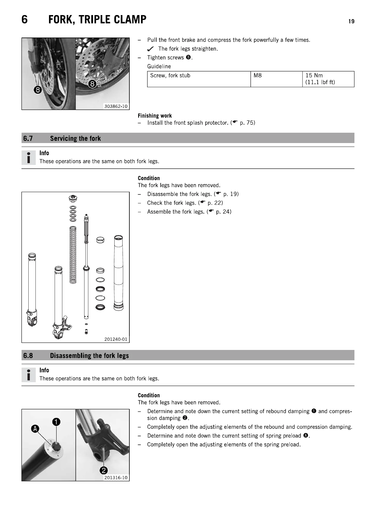
The fork chapter covers compression and rebound damping adjustment on both legs, bleeding the fork legs, cleaning the dust boots, and then the whole removal and installation sequence for the fork legs themselves. The disassembly section walks through preload adjuster removal, cartridge extraction, rebound valve removal and the sliding bushing stack, followed by a full inspection chapter with inner tube outside diameter and run-out limits and a spring length check with preload spacer guidance. Reassembly covers seal ring and dust boot fitment, sliding bushing press-in, fork oil quantity per leg, spring rate and the exact click settings for comfort, standard, sport and full payload. Steering head bearing play checking, lower triple clamp removal and installation, bearing lubrication and play adjustment close out the chapter.
Shock Absorber and Swingarm
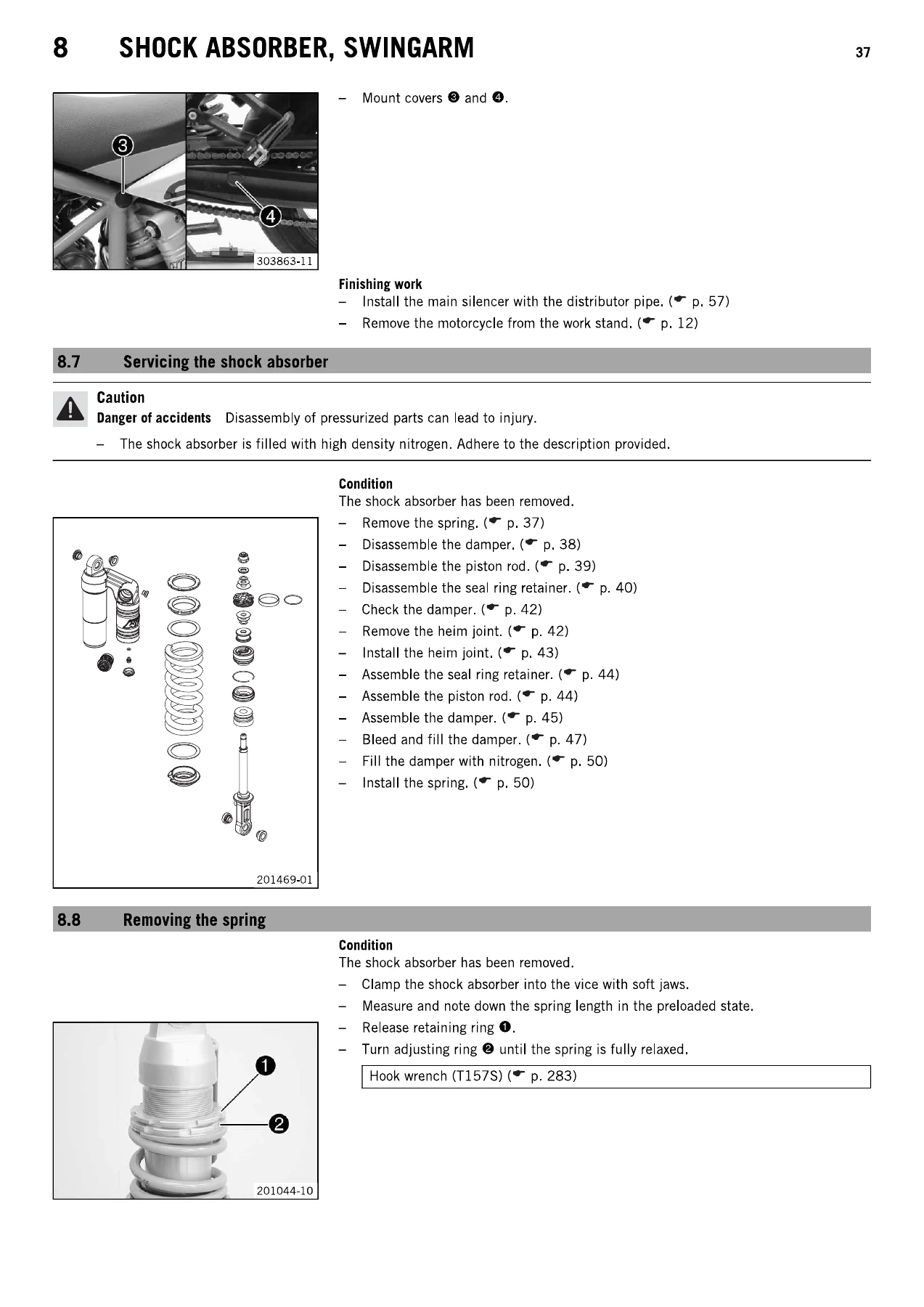
High-speed and low-speed compression damping, rebound damping and spring preload adjustment are all documented with click and turn counts per riding configuration. Beyond adjustment, the manual covers shock absorber removal and installation, spring removal, damper disassembly, piston rod disassembly, seal ring retainer work, pilot bushing replacement, heim joint removal and installation, and the full bleed-and-fill procedure using a vacuum pump with nitrogen charging at pressure. Damper cartridge bore limits, piston rod diameter and run-out limits are all given.
Engine — Removal, Disassembly and Rebuild
This is the largest part of the manual. It begins with engine removal from the frame and installation back in, then moves into engine disassembly in numbered steps: clamping to the assembly stand, preparing for teardown, starter motor and ignition coil removal, valve covers on both cylinders, spark plugs, setting the engine to ignition top dead centre on cylinder 1 and cylinder 2, camshaft removal, timing chain tensioner and timing gears, cylinder head and cylinder removal, water pump impeller, clutch cover, clutch discs and clutch basket, spread transmission, primary gear, timing chains for both cylinders, oil pump gear wheel, shift shaft, shift drum locating, locking lever, gear position sensor, alternator cover, rotor, oil filter, left engine case, crankshaft, transmission shafts and oil pumps. Individual component work covers main bearing removal and installation, main bearing shell selection by colour code, conrod bearing replacement, radial clearance measurement with Plastigauge, crankshaft support bearing, water pump bearing, cylinder head valve work, cylinder bore measurement, piston and piston ring checks, piston ring end gap, piston installation and cylinder head mounting. The assembly section reverses the entire process with the correct tightening sequences and torque steps throughout.
Fuel, Air, Exhaust and Throttle Body
Exhaust manifold and main silencer removal and installation, air filter and air filter box removal and installation, fuel tank removal, positioning and installation, fuel filter and fuel pump replacement, and fuel pressure testing are all covered. The throttle valve body chapter documents throttle position sensor circuit A zero-position check and adjustment, plus throttle valve body removal and installation.
Wheels, Chain and Brakes
Tyre air pressure and condition checks, front and rear wheel removal and installation, brake disc inspection and replacement, chain tension checking and adjustment, chain wear measurement over 18 links with a specified weight, rear sprocket and engine sprocket inspection, chain cleaning, and rear hub rubber damper checking and replacement. The brake chapter covers front and rear brake lining inspection and replacement, hand brake lever and foot brake lever basic position adjustment, front and rear brake fluid level checks, topping up, and the full brake fluid change procedure using a pressure bleeding device. Foot brake lever free travel measurement and adjustment are included with the specified value.
Electrical System, Instruments and Immobilizer
Battery removal, installation, disconnection, connection and recharging, main fuse and individual circuit fuse replacement, and the ignition curve plug-in connector used to adapt the map to fuel quality. The instruments section covers kilometres or miles selection, clock setting, TRIP 1 and TRIP 2 reset, and combination instrument wheel circumference setting through connector ED. Lighting work covers the headlight mask, headlight bulb, parking light bulb, turn signal bulb, brake light bulb, tail light bulbs and licence plate lamp. The immobilizer chapter documents activation and deactivation of black ignition keys using the orange programming key and the immobilizer blink code section gives the diagnostic flash sequences.
Clutch, Cooling and Lubrication
Hydraulic clutch fluid level and fluid change, coolant draining, filling and bleeding the cooling system, antifreeze and coolant level checks, and the compensating tank level. The lubrication chapter includes the oil circuit diagram, engine oil level checking, engine oil and filter change with oil screen cleaning, and engine oil pressure testing along with the oil jet check for clutch lubrication.
Bodywork, Routine Maintenance and Storage
Front fender, front splash protector, seat, spoiler and trim removal and refitting. Cleaning and conservation, checks and maintenance measures for winter operation, storage procedure and preparing the machine for use after storage. The service schedule chapter lays out the full interval-based maintenance plan.
Technical Data, Wiring Diagrams and Special Tools
Engine specifications and tolerances with wear limits, engine tightening torques, engine oil, coolant and fuel capacities, chassis specifications, electrical system data, tyre data, fork and shock absorber data, and chassis tightening torques. The wiring diagram runs across ten pages. Substance and auxiliary substance tables list the specified lubricants, sealants and fluids, and the special tools chapter lists every KTM tool referenced in the procedures with its part number.
Why This KTM 990 Supermoto R Repair Manual Belongs in Your Workshop
The 990 Supermoto R is a big, torque-heavy LC8 twin, and it does not respond well to guesswork. Torque values that are close enough on a small single will destroy a case bolt or distort a bearing shell on this engine. Valve clearance set by feel will cost you a cylinder head. Fork oil quantity guessed at will leave the front end unpredictable under hard braking. This manual removes all of that. It gives you the actual figures for main bearing shell selection, conrod radial clearance, piston-to-cylinder mounting clearance, piston ring end gap, cylinder head nut tightening steps, camshaft bearing support torque, and every chassis and engine fastener on the machine. When the job is a diagnosis rather than a repair, the immobilizer blink code section and the throttle position sensor checks give you a defined path instead of parts swapping.
Because it is organised the way the work is actually done, it suits both the home mechanic building up to a big job and the professional who wants the factory procedure in front of them. If you are servicing your own fork, changing your own clutch discs, replacing the water pump bearing, pulling the swingarm or stripping the top end for a valve check, the sequence is written out step by step with the tools and values you need at each stage. If you are going deeper — splitting the cases, replacing main bearings, rebuilding the transmission, changing the conrod bearing — the manual carries you through the measuring and selecting stages that decide whether the rebuild lasts.
IMAGES PREVIEW
The KTM 990 Supermoto R 2011 repair manual is delivered as an instant PDF download. There is no shipping, no waiting and no physical book to keep clean in the workshop. Open it on a laptop, tablet or phone at the bench, print the pages you need for the job in front of you and leave the rest on file, or print the whole manual and keep it with the bike. Either way, you get the complete 2011 990 Supermoto R workshop documentation the moment payment clears.
Reviews
There are no reviews yet.