Kyocera FS-6525MFP FS-6530MFP Multifunction Laser Printer Service Manual PDF
Original price was: $70.00.$19.95Current price is: $19.95.
Official Kyocera factory service manual for FS-6525MFP and FS-6530MFP multifunction laser printers. This comprehensive 332-page technical manual covers installation, maintenance, troubleshooting, and repair for these 25ppm/30ppm black & white MFPs.
Includes complete specifications, assembly/disassembly procedures, maintenance mode operations, self-diagnostic codes, paper misfeed detection, image formation troubleshooting, electrical/mechanical schematics, PWB replacement, firmware updates, and wiring diagrams for qualified Kyocera service technicians.
Description
Kyocera FS-6525MFP FS-6530MFP Multifunction Laser Printer Service Manual – PDF DOWNLOAD
DESCRIPTION
This is the official Kyocera FS-6525MFP/FS-6530MFP Service Manual (Part Number 842MW113/2MWSM063, Revision 3, December 2012) for these desktop multifunction laser printer systems. This comprehensive 332-page technical manual provides complete service information for authorized Kyocera service personnel to install, maintain, troubleshoot, and repair these professional office MFPs.
Models Covered
This Kyocera multifunction printer repair guide covers:
- FS-6525MFP – 25 pages per minute multifunction laser printer
- FS-6530MFP – 30 pages per minute multifunction laser printer
Both models share identical architecture with different print engine speeds.
Product Overview
The Kyocera FS-6525MFP and FS-6530MFP are desktop multifunction laser printers designed for high-volume office environments, combining print, copy, scan, and optional fax capabilities in robust, reliable systems.
Key Functions:
- Black & white laser printing
- Walk-up copying
- Color scanning
- Optional fax system
- Network connectivity
- Document processing
Complete Technical Specifications
General Specifications:
Machine Type: Desktop multifunction printer
Printing Method: Electrophotography by semiconductor laser, single drum system
Print Speed:
- FS-6525MFP: 25 pages per minute
- FS-6530MFP: 30 pages per minute
Original Handling:
Original Types: Sheet, book, 3-dimensional objects
Maximum Original Size: A3/Ledger
Original Feed System: Fixed platen (optional document processor available)
Paper Handling:
Paper Weight:
- Cassette: 60-163 g/m² (Duplex: 60-163 g/m²)
- MP Tray: 45-256 g/m² (Sizes larger than A4/Letter: 52-163 g/m²)
Paper Types:
Cassette Support:
- Plain, Preprinted, Bond, Recycled, Vellum, Rough
- Letter Head, Color, Prepunched, Thick, High Quality
- Custom 1-8 (Duplex: Same as simplex)
MP Tray Support:
- Plain, Preprinted, Bond, Recycled, Vellum, Rough
- Letter Head, Color, Prepunched, Thick, High Quality
- Envelope, Cardstock, Transparency, Labels
- Custom 1-8
Paper Sizes:
Cassette:
- A3, A4, A5, B4, B5, Ledger, Letter, Legal, Statement
- Oficio II, Folio, 8K, 16K
MP Tray:
- A3, A4, A5, A6, B4, B5, ISO B5, B6
- Ledger, Letter, Legal, Statement, Executive
- Oficio II, Folio, 8K, 16K
- Envelope #10, #9, #6, Monarch, DL, C4, C5
- Postcards, Return postcard, Youkei 2, Youkei 4
- Custom sizes
Zoom/Reduction/Enlargement:
- Manual Mode: 25-400% in 1% increments
- Auto Mode: 400%, 200%, 141%, 122%, 115%, 86%, 81%, 70%, 50%
Duplex Printing:
- Automatic duplex unit (standard)
- Duplex paper weight: 60-163 g/m²
- Duplex paper sizes: Multiple standard sizes
Image Scanner:
- Color scanning capability
- CCD sensor technology
- Scan resolution specifications
- Scan to email, FTP, SMB
Optional Components:
- Document processor (DP-470/AK-470)
- Paper feeder (PF-470/471)
- Document finisher (DF-470)
- FAX System (U)
- Expansion memory
Comprehensive Manual Contents
REVISION HISTORY:
- Revision 1: June 20, 2012
- Revision 2: August 20, 2012
- Revision 3: December 1, 2012
SAFETY PRECAUTIONS: Comprehensive safety guidelines for service personnel including:
- DANGER – High risk warnings
- WARNING – Serious injury warnings
- CAUTION – Equipment damage warnings
SECTION 1-1: SPECIFICATIONS
1-1-1 Machine Specifications:
- Complete technical specifications
- Print speed and resolution
- Paper capacity
- Media types and sizes
- Zoom capabilities
- Duplex specifications
1-1-2 Parts Names:
- Machine (Front Side) – Front panel components identification
- Machine (Rear Side) – Rear panel connections
- Operation Panel – Control panel layout and buttons
1-1-3 Machine Cross Section:
- Internal component layout
- Paper path diagram
- Major assembly locations
SECTION 1-2: INSTALLATION
1-2-1 Installation Environment:
- Site requirements
- Environmental specifications
- Temperature and humidity ranges
- Ventilation requirements
- Power requirements
1-2-2 Unpacking and Installation:
- Installation Procedure – Complete step-by-step installation
- Unpacking instructions
- Removing protective materials
- Physical installation
- Setting Initial Copy Modes – Initial configuration
1-2-3 Install Expansion Memory (Option):
- Memory upgrade procedures
- Memory slot location
- Installation steps
- Verification procedures
1-2-4 Option Composition:
- Available options overview
- Option compatibility
- Installation requirements
SECTION 1-3: MAINTENANCE MODE
1-3-1 Maintenance Mode:
- Executing a Maintenance Item – Access procedures
- Maintenance Mode Item List – Complete list of maintenance functions
- Contents of Maintenance Mode Items – Detailed descriptions of each maintenance function (extensive coverage)
1-3-2 Service Mode:
- Printing the Service Status Page – System information printout
- Executing a Service Mode – Entering service mode
- Description of Service Mode – Complete service mode functions
SECTION 1-4: TROUBLESHOOTING
1-4-1 Paper Misfeed Detection:
- Paper Misfeed Indication – Error display and location
- Paper Misfeed Detection Condition – Sensor-based detection
- Paper path sensor locations
- Detection timing
- Clearance procedures
1-4-2 Self-Diagnostic Function:
- Self-Diagnostic Function – Automatic error detection
- Self Diagnostic Codes – Comprehensive error code list with descriptions and solutions
- Error code interpretation
- Resolution procedures
1-4-3 Image Formation Problems: Extensive troubleshooting for print quality issues:
- No Image Appears (Entirely White) – Causes and solutions
- No Image Appears (Entirely Black) – Diagnostic steps
- Image is Too Light – Adjustment procedures
- Background is Colored – Cleaning and replacement
- White Streaks Printed Vertically – Drum/roller issues
- Black Streaks Printed Vertically – Contamination
- Streaks Printed Horizontally – Feed problems
- One Side Darker Than Other – Alignment issues
- Spots are Printed – Component wear
- Image is Blurred – Focus and registration
- Leading Edge Misalignment – Consistent and sporadic
- Paper is Wrinkled – Fuser and pressure issues
- Offset Occurs – Transfer problems
- Part of Image Missing – Memory or data issues
- Fusing is Loose – Temperature adjustments
- Image Out of Focus – Optical issues
- Image Center Misalignment – Registration adjustment
1-4-4 Electric Problems:
- Electrical troubleshooting flowcharts
- Power supply issues
- Circuit board failures
- Component testing procedures
1-4-5 Mechanical Problems:
- Mechanical troubleshooting
- Drive system issues
- Roller and clutch problems
- Motor malfunctions
1-4-6 Send Error Codes:
- Scan to SMB Error Codes – Network folder scanning errors
- Scan to FTP Error Codes – FTP transfer errors
- Scan to E-mail Error Codes – Email sending errors
- Complete error code tables with solutions
SECTION 1-5: ASSEMBLY AND DISASSEMBLY
1-5-1 Precautions for Assembly and Disassembly:
- General precautions
- Drum unit handling
- Toner handling
- Genuine Kyocera toner identification
1-5-2 Outer Covers:
- Detaching/Refitting Front Cover
- Detaching/Refitting Rear Cover
- Detaching/Refitting Inner Tray
- Detaching/Refitting Eject Rear Cover
1-5-3 Paper Feed Section:
- Primary Paper Feed Unit – Removal and installation
- MP Paper Feed Roller and Separation Pad – Replacement
- Registration Roller – Service procedures
- Registration Cleaner – Maintenance
- MP Tray – Removal procedures
1-5-4 Developing Section:
- Developing Unit – Complete removal and installation procedures
1-5-5 Drum Section:
- Drum Unit – Careful handling procedures
- Charger Roller Unit – Replacement steps
1-5-6 Transfer/Separation Section:
- Transfer Roller Unit – Removal and installation
1-5-7 Fuser Section:
- Fuser Unit – High-temperature component removal
- Safety precautions for hot components
1-5-8 Drive Section:
- Main Motor – Drive motor replacement
- Drive Unit – Complete drive train service
1-5-9 Optical Section:
- Laser Scanner Unit – Laser unit service
- Image Scanner Unit – CCD scanner service
- LED Unit – Status indicator replacement
1-5-10 Document Processor:
- Document Processor – Complete DP removal
- DP Paper Feed Roller and Separation Pulley – Feed mechanism
- DP Main PWB – Control board replacement
1-5-11 PWBs (Printed Wiring Boards):
- Main PWB – Main control board
- Engine PWB – Print engine control
- Power Source PWB – Power supply board
- Operation Panel PWB Main – User interface board
- High Voltage PWB – HV generation board
1-5-12 Others:
- Language Sheet – Panel overlay replacement
- Conveying Unit – Paper path components
- Eject Fan Motor – Cooling system
- Principal Fan Motors – Installation direction specifications
SECTION 1-6: REQUIREMENTS ON PWB REPLACEMENT
1-6-1 Upgrading the Firmware:
- Firmware update procedures
- Version verification
- Update methods
- Backup procedures
1-6-2 Remarks on PWB Replacement:
- Engine PWB – Configuration requirements
- DP Main PWB – Settings transfer
- Main PWB – System reconfiguration
- Important notes for each board type
SECTION 2-1: MECHANICAL CONSTRUCTION
2-1-1 Paper Feed/Conveying Section:
- Cassette Paper Feed Section – Feed mechanism operation
- MP Tray Paper Feed Section – Multi-purpose feed
- Conveying Section – Paper transport system
2-1-2 Drum Section:
- Drum unit construction
- Charging system
- Drum rotation mechanism
2-1-3 Developing Section:
- Developer unit construction
- Toner supply system
- Developer roller drive
2-1-4 Optical Section:
- Image Scanner Section – CCD scanning mechanism
- Laser Scanner Section – Laser exposure system
- Polygon mirror operation
- Lens and mirror assembly
2-1-5 Transfer/Separation Section:
- Transfer roller construction
- Paper separation mechanism
- Charge elimination
2-1-6 Fuser Section:
- Heat roller assembly
- Pressure roller system
- Temperature control
- Fuser drive mechanism
2-1-7 Eject/Feedshift Section:
- Paper eject mechanism
- Output tray system
- Path switching
2-1-8 Duplex Conveying Section:
- Duplex unit construction
- Paper reversal mechanism
- Duplex paper path
2-1-9 Document Processor:
- Original Feed Section – ADF feed mechanism
- Original Conveying Section – Document transport
- Original Switchback/Eject Sections – Duplex scanning
SECTION 2-2: ELECTRICAL PARTS LAYOUT
2-2-1 Electrical Parts Layout:
- PWBs – All circuit board locations
- Switches and Sensors – All sensor positions
- Motors – Motor locations and specifications
- Others – Solenoids, clutches, lamps
- Document Processor (PWBs and Sensors) – DP electrical
- Document Processor (Motors and Clutches) – DP mechanical
SECTION 2-3: OPERATION OF THE PWBs
2-3-1 Main PWB:
- Block diagram
- CPU and memory
- Interface circuits
- Communication functions
- Control logic
2-3-2 Engine PWB:
- Print engine control
- Motor drive circuits
- Sensor input processing
- Laser control
- High voltage control interface
2-3-3 Power Source PWB:
- Power supply circuits
- Voltage regulation
- Power distribution
- Protection circuits
2-3-4 Operation Panel PWB Main:
- Display control
- Button input processing
- LED indicators
- Panel interface
2-3-5 DP Main PWB:
- Document processor control
- ADF motor control
- Scanner interface
- Sensor processing
SECTION 2-4: APPENDIXES
2-4-1 Appendixes:
- Maintenance Kits – Periodic maintenance part kits
- Repetitive Defects Gauge – Print quality diagnosis tool
- Firmware Environment Commands – Service commands
- Chart of Image Adjustment Procedures – Quality optimization flowchart
- Wiring Diagram – Complete electrical schematics
Installation Guides (Included)
Paper Feeder (PF-470/471):
- Installation procedures
- Configuration settings
- Testing
Document Finisher (DF-470/AK-470):
- Finisher installation
- Stapling unit setup
- Adjustment procedures
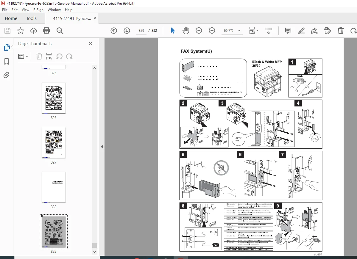
FAX System (U):
- Fax board installation
- Line connection
- Configuration
Safety Information
Installation Precautions: ⚠ Use correct power supply voltage
⚠ Proper grounding required
⚠ Stable, level surface
⚠ Adequate ventilation space
⚠ Avoid humid/dusty locations
Maintenance Precautions: ⚠ Disconnect power before disassembly
⚠ Follow specified procedures
⚠ Do not bypass safety features
⚠ Use correct replacement parts
⚠ Fuser section extremely hot
⚠ High voltage in charger sections
⚠ Laser safety – do not disassemble optical unit
Battery Warning: ⚠ Risk of explosion if replaced incorrectly
⚠ Dispose according to local regulations
⚠ Contains lithium – environmental hazard
Toner Handling: ⚠ Avoid excessive inhalation
⚠ Protect eyes
⚠ Do not dispose in fire
⚠ Proper cleaning procedures
Who Needs This Manual?
This Kyocera laser MFP technical documentation is essential for:
- Authorized Kyocera service technicians
- Office equipment service companies
- Corporate IT service departments
- Technical training centers
- Anyone performing authorized service on FS-6525MFP/FS-6530MFP
Prerequisites:
✓ Kyocera service training
✓ Understanding of laser printer technology
✓ Electronic troubleshooting skills
✓ Mechanical repair aptitude
✓ ESD handling procedures
✓ Safety training for high voltage and high temperature components
FILE DETAILS
| Detail | Specification |
|---|---|
| Manual Title | Service Manual FS-6525MFP/FS-6530MFP |
| Models Covered | FS-6525MFP (25ppm), FS-6530MFP (30ppm) |
| Part Number | 842MW113 / 2MWSM063 |
| Revision | Revision 3 |
| Publication Date | December 2012 |
| First Edition | June 2012 |
| Pages | 332 pages |
| PDF Quality | High-quality technical manual with detailed diagrams and photographs |
| File Size | 19.4 MB |
| Page Size | Letter (612 x 792 pts) |
| Language | English |
| Copyright | Kyocera Document Solutions |
| PDF Version | 1.4 |
| Source Note | Downloaded from ManualsLib.com |