

Liebherr CBW 60(40)/36/16(24,3)28 Deck Crane Operating Manual Volume 1 – PDF Download
Original price was: $49.95.$29.95Current price is: $29.95.
Volume 1 operating manual for the Liebherr CBW 60(40)/36/16(24,3)28 cargo deck crane, serial numbers 166009 and 166010 – covering start-up, daily operation, emergency procedures and maintenance.
Description
Liebherr CBW 60(40)/36/16(24,3)28 Deck Crane Operating Manual – Volume 1
This is Volume 1 of the operating manual issued for the Liebherr CBW 60(40)/36/16(24,3)28 electro-hydraulic ram luffing cargo deck crane, serial numbers 166009 and 166010, version 001 dated 29.05.2008. Volume 1 is the volume that covers start-up, operation and maintenance of the machine. The technical information for electrical and hydraulic systems sits in Volume 2, and the spare parts catalogue in Volume 3, but everything an operator, ship’s engineer or shore-side technician needs to run and care for this deck crane day to day is contained in this first volume.
File Details
- Manual type: Operating manual, Volume 1 – start-up, operation, maintenance
- Brand: Liebherr
- Machine type: CBW 60(40)/36/16(24,3)28 / CBW Standard cargo deck crane
- Serial numbers: 166009 and 166010
- Version: 001 – 29.05.2008
- Language: English
- Pages: 160
- File format: PDF
- Publisher: LIEBHERR-WERK NENZING GMBH, Austria
Chapters Covered
- 1. Introduction – foreword, using the documentation, machine’s passport
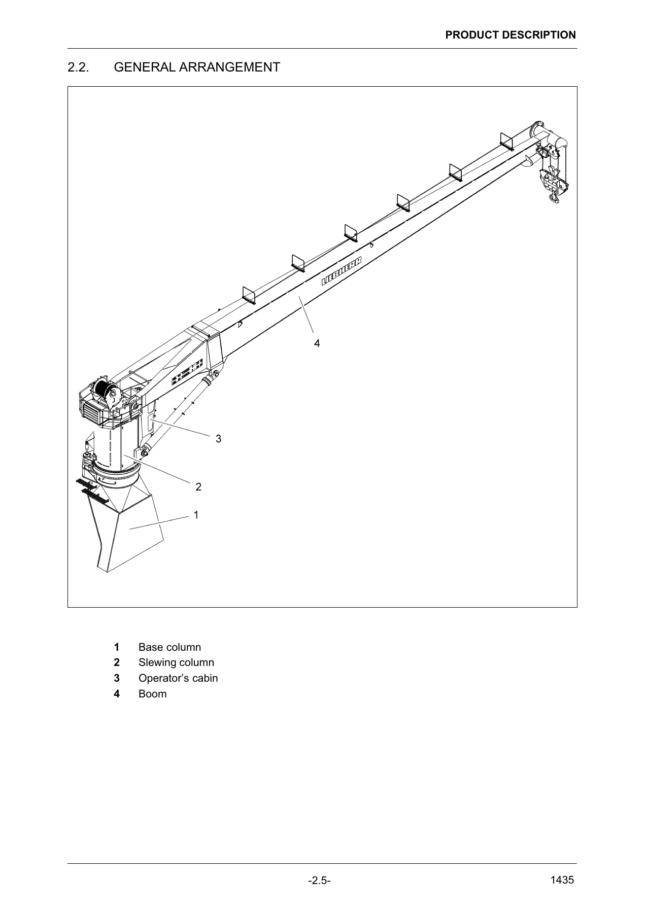
- 2. Product Description – general, general arrangement, technical data, load diagrams for 2-fall and 3-fall main hoist operation
- 3. Safety Guideline – utilization as directed, areas of responsibility, personal requirements of the crane operator, personal protective gear, work area, safety and monitoring devices, safety signs on the machine, machine specific dangers, additional dangers, notes on safety
- 4. Control and Operating Elements – control lever, control panel X20, switch cabinet
- 5. Crane Operation – safety and rescue equipment, checks before daily start-up, daily start-up, start/stop for a work break, shutting down the crane, crane operation
- 6. Emergency Operation – arrangement of emergency devices, emergency hand pump, procedure to lower the load, procedure to release the slewing brakes, procedure to lower the boom, procedure to operate the interlock system
- 7. Maintenance – qualified persons, service spare parts and standard tools, maintenance intervals, electric motor, gearboxes, multiple disc brakes, ropes, rope pulleys, hydraulic lines and hoses, hydraulic oil tank, Liebherr Condition Monitoring, pressure accumulators, maintenance of oil coolers, electrical system, slip ring unit
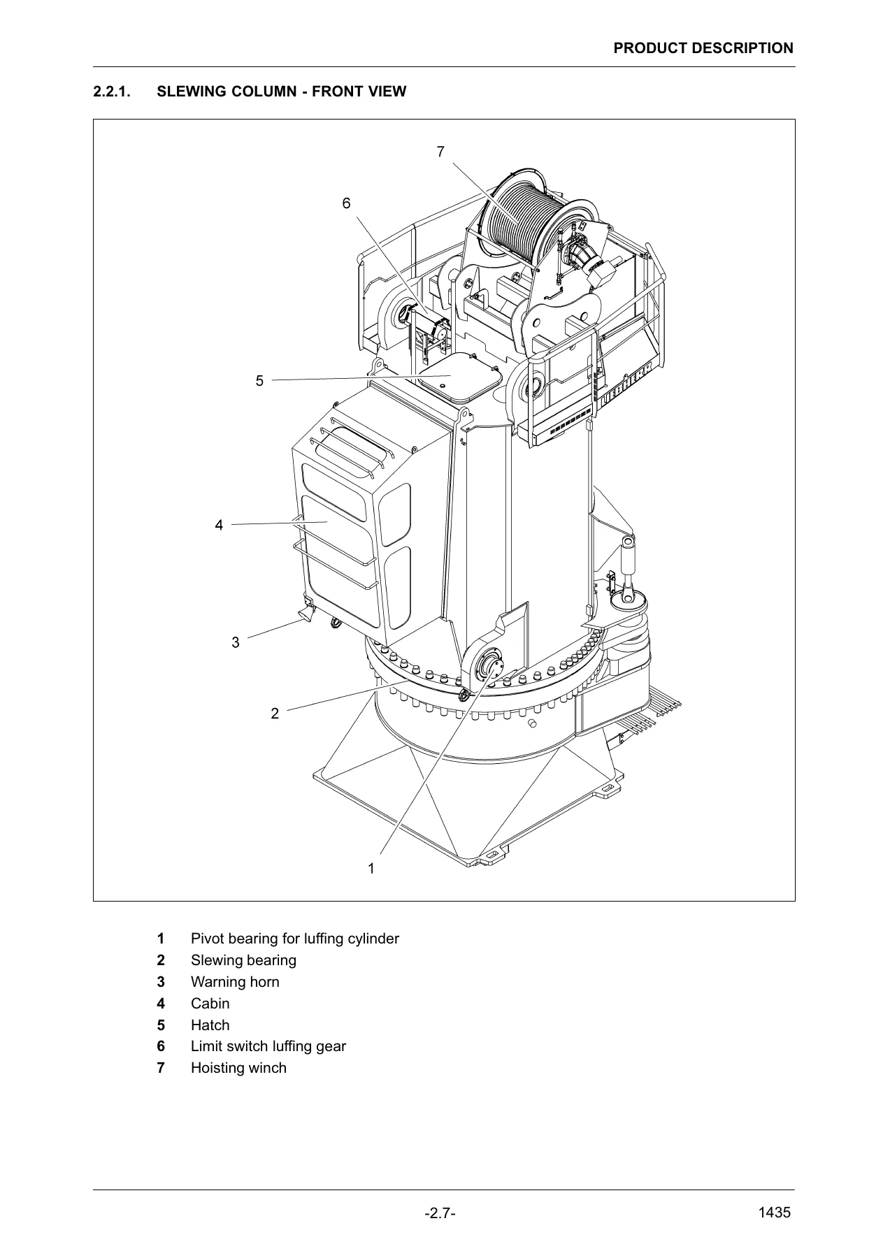
Read together, these seven chapters take the reader from the machine’s passport page through the layout of the slewing column, machinery room, power pack, cabin and boom, and then into the working procedures themselves. The document is written for a crane that is fixed-installed on a ship and used to load and unload that ship at a quay, and the operating content reflects that duty cycle: harbour operation, anchor or lashed at the quay, fully ballasted, with the load charts in the product description chapter governing every lift.
The Machine This Manual Covers
The CBW Standard cargo deck crane described here is an electro-hydraulic ram luffing deck crane with maintenance-free hydraulic luffing cylinders, a hydraulic load sensing control system, continuously variable speed control from zero to maximum, and the ability to run all three motions at the same time. The manual documents a 60 metric tonne main hoist system with hook block parking, a slew interlock system and flood lights on the boom among the fitted options. Working range for the main hoist gear runs from a 1,8 m minimum radius in 2-fall operation up to a 28 m maximum radius, and from a 3 m minimum radius up to 16 m at 15 degrees boom inclination in 3-fall operation.
Hoisting speed is quoted at 0 to 21 m/min with 40 metric tonnes on 2-fall, 0 to 35 m/min with an empty hook on 2-fall, 0 to 14 m/min with 60 metric tonnes on 3-fall and 0 to 23 m/min with an empty hook on 3-fall, with a hoisting height of approximately 52 m. Luffing takes around 100 seconds from maximum to minimum radius at full load, and the slewing gears turn at 0 to 0,75 rpm with full load at maximum radius. Main motor power supply is 440 V, 60 Hz, three phase, with a 230 V, 60 Hz, three phase auxiliary supply. Total crane weight is approximately 54,9 tonnes. These are the numbers a lift plan is built on, and they appear in full in the technical data chapter and on the two load diagrams.
Safety Content Built Around a Deck Crane
The safety guideline chapter is not boilerplate. It works through machine-specific dangers on this crane – injuries from mechanical parts, injuries from hydraulic energy, burns from surfaces above 65 degrees C, fire and explosion risk while tanking, environmental protection – and then adds the additional dangers that come with the installation: wind and storm effects on the boom and load, snow and ice loads on the boom and on the optional walkways, and lightning strikes. The Beaufort wind force table with descriptions of sea state, wind speed in knots and wave height gives the operator a practical way to estimate conditions when the machine is not in operation, and the manual is explicit that at wind speeds above 25 m/s the complete boom must be laid down in rest position.
The same chapter covers the areas of responsibility for the owner and the operator, the personal requirements of the crane operator, the protective gear required, and the safety and monitoring devices fitted to the machine – helicopter warning light, emergency stop keys, horn and acoustic transmitters, fire extinguisher, and the shut-off valve for the hydraulic tank. The safety signs on the machine and the safety label inside the cabin are reproduced with their meaning explained, so the operator can match what is on the crane to what the manual says it should say. Banksman, rigger and hand signal sections follow, including hand signals in accordance with BGV A8 and ASME/ANSI B30.5.
Daily Operation, Start-Up and Shutdown
The crane operation chapter walks through the checks that belong to a daily start-up, the inspection tour, the checks before powering up, the starting sequence for the main motor, moving the hook out of the hook garage, unlocking the crane interlock system, stopping and restarting for a work break, and the full shutdown procedure. The parking sequence is dealt with in detail because this crane has a hook garage and a slewing interlock: the boom is brought to minimum working radius, the key switch for hook parking is turned, the bypass park position key switch is held, the hook is stowed, the boom is lowered to horizontal, and the slewing column is turned into its interlock position and locked. Each step is illustrated with the relevant control panel.
Also included is the emergency rescue device in the cabin – the emergency descent equipment with rescue harness, karabiner and rope, described step by step with the warning that the procedure should be trained before an emergency occurs, and that the equipment must be inspected by a qualified person once a year.
Emergency Operation
With a hydraulically controlled multi disc brake that closes without pressure, a total standstill of the crane leaves the load, the boom and the slewing brakes in a state that can only be released manually. The emergency operation chapter documents the emergency hand pump and the exact valve positions for lowering the load, releasing the slewing brakes, lowering the boom with an empty hook block, lowering the boom with the hook block in the hook garage, and operating the interlock system. Valve references H62, H62A, H62B, H63, D62, D63, E60 and E69 are identified by location – at the hoisting winch, near the hoisting motor, at the top of the hydraulic tank, at the slewing gears, at the bottom of the hydraulic tank by the suction line – with the normal positions to be restored once the emergency operation is finished.
Maintenance Intervals, Lubrication and Wear Limits
The maintenance chapter opens with the interval tables built around operating hours – 10 hours daily, 50 hours weekly, 100 hours, 250 hours, 500 hours, 1000 hours and 2000 hours – covering the greasing system, hydraulic system, slewing gearboxes and slewing bearing, and the hoisting winch. Then it goes component by component. The electric motor section includes the rating plate and lubrication plate data for the ABB motor, the grease quantity table by mounting position and speed, and the procedure for regreasing with the grease outlet opened first. The gearbox sections cover oil level inspection and oil change for the slewing gearboxes and the hoisting winch gearbox. The multiple disc brake section explains that these brakes are holding brakes only and are subject to very little wear except after an emergency stop under full load, at which point they must be inspected.
The rope section is extensive, running from condition before installation and uncoiling through installation, untwisting of hoist ropes, maintenance, examination, discard criteria, operating performance and storage. Wire break tables, the 7 percent diameter reduction limit for external wear, the 10 percent limit for corrosion and abrasion, and the deformation illustrations for waviness, basket or lantern deformation, core or strand protrusion, kinks, bends and heat damage give a competent person everything needed to pass or fail a rope. A separate section covers rope pulleys, including the test template method for checking winch drum groove base and pulley grooves, wear tolerances and cleaning of plastic pulleys.
Hydraulic lines and hoses, the hydraulic oil tank with its return flow filter and breather filter, the Liebherr Condition Monitoring oil analysis programme with sampling instructions and the sampling points on the hydraulic tank, slewing gear and hoisting winch, pressure accumulator safety instructions, oil cooler cleaning, the electrical system and the slip ring unit round out the chapter.
What This Manual Lets You Do
With Volume 1 in hand a qualified operator can start this CBW deck crane correctly, run it within its load chart, park it for sea, and bring it back into service after a break. A ship’s engineer or shore technician can carry out the daily and weekly greasing and fluid checks, read the maintenance interval tables, replace filter elements, inspect ropes against the discard criteria, check gearbox oil levels, and know exactly which tasks are marked for LIEBHERR service personnel only. In an emergency, the valve-by-valve hand pump procedures allow a load to be lowered, the slewing brakes released or the boom brought down without power.
Correct procedures and the right specifications matter on a deck crane because the consequences of a wrong lift plan or a missed rope defect are not confined to the machine. The load charts, the wind limits, the boom parking position and the rope discard criteria in this manual are the difference between a routine cargo operation and an incident on a working deck.
IMAGES PREVIEW
Delivery is instant. The file is a PDF that downloads immediately after payment, with no shipping and no waiting for a parcel. It opens on a laptop, tablet or phone, and any page or section can be printed for use at the crane or in the workshop.

Reviews
There are no reviews yet.