

Liebherr PR 776 Parts Catalog Type 1296 Serial 19494 — 1048-Page Illustrated Spare Parts Manual PDF
Original price was: $71.95.$44.95Current price is: $44.95.
Complete 1048-page illustrated spare parts catalog for the Liebherr PR 776 crawler dozer, Type 1296, machine serial 19494. Every assembly is itemised with part numbers, quantities and descriptions alongside component drawings, in Russian and English.
Description
Liebherr PR 776 Parts Catalog — Type 1296, Machine Serial 19494
The Liebherr PR 776 crawler dozer runs on a fully illustrated spare-parts system, and this parts catalog for Type 1296, machine serial 19494, is the complete 1048-page reference built for it. Every assembly is itemised — position number, Liebherr part number, quantity and description — and each group sits with the component drawing needed to identify the correct part before an order leaves the desk. The catalog is bilingual: Russian and English appear together in the column headings and item lines, so the same page reads correctly for a Russian-speaking parts counter and an English-speaking workshop.
File Details
- Document type: Illustrated spare parts catalog
- Brand: Liebherr
- Model: PR 776
- Type: 1296
- Machine serial: 19494
- Languages: Russian and English
- Page count: 1048 pages
- File format: PDF
- Date shown on the pages: 7.10.2019
Chapters Covered
- 00 10 000 00 — BASIC MACHINE
- 00 10 100 00 — RUNNING GEAR
- 00 10 200 00 — MOTOR
- 00 10 300 00 — COOLING SYSTEM
- 00 10 400 00 — FUEL SYSTEM
- 00 10 500 00 — HYDRAULIC INSTALLATION
- 00 10 600 00 — OPERATOR WORK PLACE
- 00 10 700 00 — HEATER/AIR CONDITIONING
- 00 10 800 00 — BODY/COVERS
- 00 10 900 00 — ELECTRIC
- 00 11 000 00 — SIGNS
- 00 11 100 00 — FILLING FLUIDS
- 00 11 200 00 — TOOL EQUIPMENT
- 00 11 400 00 — SERVICE MATERIAL
- 00 20 000 00 — EQUIPMENT
- 00 20 100 00 — SHIELD/SHOVEL
- 00 20 200 00 — PUSH FRAME/SHOVEL ARM
- 00 20 400 00 — REAR RIPPER
How the Catalog Is Built
The contents page lists the ten sub-groups beneath BASIC MACHINE with their group numbers, so an enquiry can be routed to the right chapter before a single drawing is opened. From there the catalog descends into individual assemblies, each with a position-numbered drawing and a matching item table. Part numbers are printed exactly as Liebherr issues them, quantities are given per assembly, and descriptions name the component rather than leaving it to the drawing alone. Group numbers such as 10 31 811 1, 11 08 250 1 or 12 80 784 4 appear at the head of each page, which makes it possible to quote a page and a position number over the phone and have the correct part pulled without ambiguity.
Where Liebherr splits a component by machine build, the catalog carries that split in the item table itself. Serial break markers appear against individual positions, so a roller, brake, cylinder or valve listing can be narrowed to the correct version for a given machine rather than guessed at from the drawing.
Basic Machine and Frame Group (00 10 000 00)
The base group covers the main frame and the structural hardware that ties the machine together. The frame assembly (12 81 086 0) is broken down with the cross member cpl. (12 81 087 7), clamping sleeves, bushings and the driver’s platform supports. The frame head assembly carries its own bushings, and the access ladder and left-hand ascent groups list their railings, antisclide coatings, fasteners and countersunk screws. Axle shell and cross member entries are itemised separately, which matters when a machine has been in service long enough for the structural bushes to need replacing.
Running Gear and Undercarriage (00 10 100 00)
This is the largest single block of the catalog and the one most buyers come for. The undercarriage assembly (10 31 811 1) and its left- and right-hand frame groups (10 31 811 3 and 10 31 821 7) list axles, sheets, tapered socket washers, spherical washers, axle shells, sealing rings, thrust washers, locking rings and dowel pins. The roller frame groups carry the 200/220X130 and 150/170X80 bushings, guiding tapes, double locking rings and sealing rings.
Track rollers are catalogued in their own group (11 08 250 1 and 11 08 250 2) for single-flange and double-flange D10N rollers. Each roller breaks down to axle, bushings, washers, bushing retainer, screws, O-rings, axial face seals and the outer end piece, with plug cpl. and regulating washers listed alongside.
The track group (12 80 784 4) covers the 610 mm crawler chain: right- and left-hand track links, masterlinks, chain belt, bushings, pins, locking rings, distance rings, seals and stop plugs, plus the track pad screws, UNF1 1/8X12 nuts and single grouser plates. The extension group with carrier roller adds bogie wheel supports, single-flange D10N rollers and their bearing blocks.
Idler and guide wheel units (10 31 814 7 and 10 31 814 8) are itemised with guide wheel D10N, bearing blocks, bearing covers, pendulum bearings, guide bushings, buffers, retaining plates, grease nipples and pressure limiting valves. The double pendulum groups for front and rear (10 31 817 1 and 10 31 820 2) list rockers, chain guides, covers and the fasteners that hold them. The equalizer bar assembly (10 31 901 2) covers the suspension member, pin 120X412, bushing 120/146X198, sealing rings, dowel pins, ventilation valve, pin 88,9X305, hinge bearings, locking rings, hydraulic-type lubricating nipples, covers, hoses and the bloc cpl. that follows it.
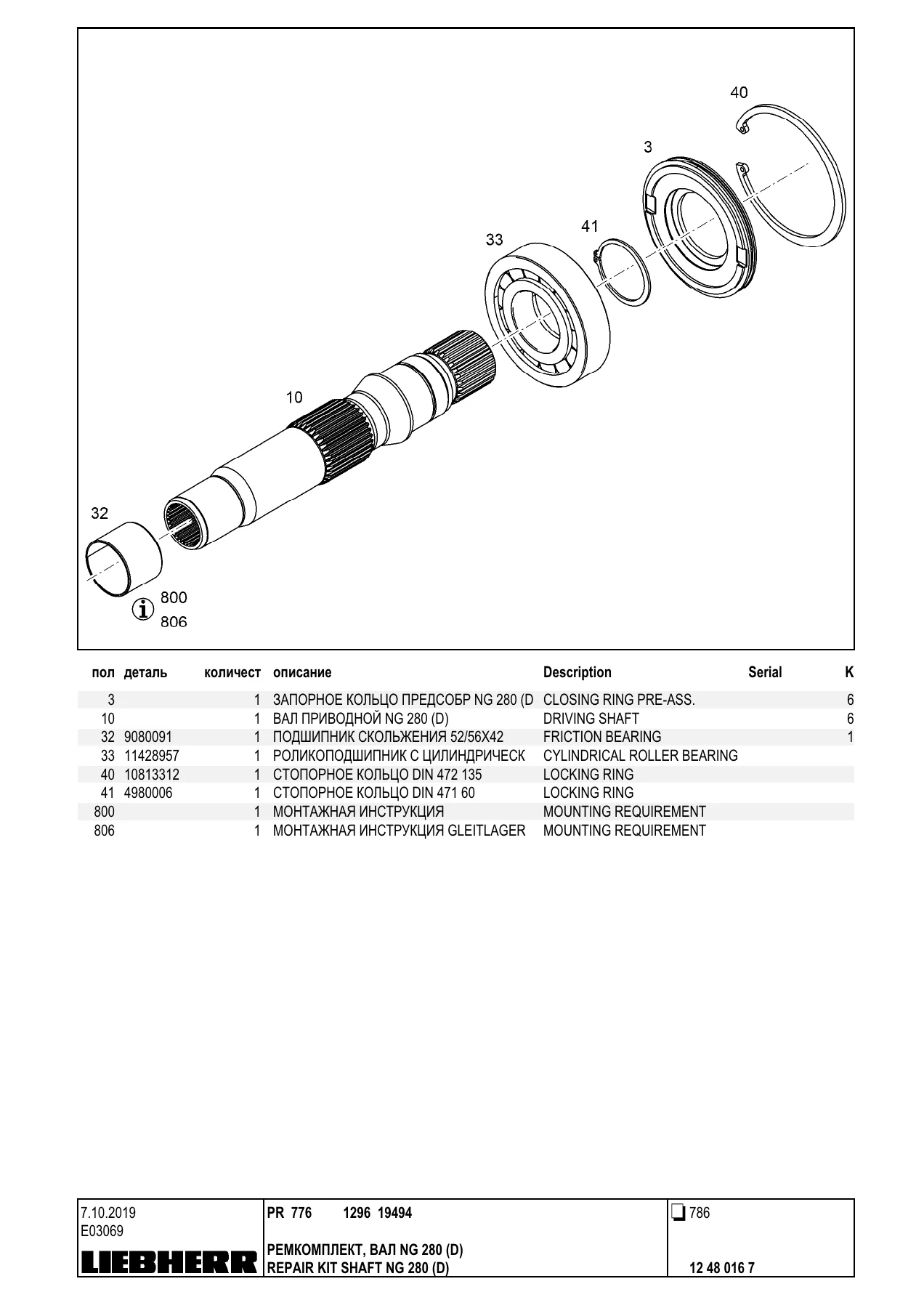
Final drive parts sit in the undercarriage drive group (11 38 951 8), which lists the traction drive FAT 800F538 for left and right separately, the hex screws and washers that mount them, and the hydraulic attachment motors. The traction drive repair sections break the unit into housing, drive shaft, cylindrical roller bearings, spur wheel, sun wheel, planet wheels, planet pins, planetary carriers, tapered roller bearings, adjusting nut, support flange, retaining disks and the axial face seals at each end.
Motor Group and Diesel Engine Breakouts (00 10 200 00)
The motor arrangement (10 31 900 6) opens with the motor support, the motor and pump assembly, the engine air installation and the exhaust installation. Alongside it sit the quick oil drain, the thermal insulation of the exhaust system and the water heater group with its mounting, hose connections, auxiliary fuel system heater, electrical base and central electrics units, plus the cabin electrical package and circuit diagram.
The D9512 A7 diesel engine is then taken apart group by group. Crankcase assemblies with cylinders and cylinder liners, O-rings and sealing plugs. Crankshaft with gear, main bearing sets, crankshaft sealing. Connecting rods with big-end bearing repair kits and conrod bolts. Pistons cpl. d=128 with KB-ring, piston ring MG, DSF ring, piston bolt and snap rings. Cylinder head assemblies with head gaskets, cylinder screws, parallel pins, valve stem seal rings, spring supports, valve collets, valve springs, inlet and outlet valves, plus the rocker arm device with supports, adjusting screws and locking rings. Camshafts with gearwheels. Oil module assemblies for left and right with oil cooler housings, oil coolers, oil filter housings, filter holders, non-return valves and the oil line assembly. Lubricating oil pumps. Final control valves with their pipelines, O-rings and distance sleeves. High-pressure pumps with their drives, gearwheels, covers and coupling ferrules. Injection nozzles and pressure adapters. Fuel prefilter and fine filter assemblies with filter brackets, manual ventilation pumps and lines. Fuel lines and injection lines. Air intake and charge air line assemblies with pipe sockets, retainer clips and rubber connections. Water pump with fastening. Thermostat housing assemblies. Exhaust pipe assembly and outlet manifold with compensators, seals and heat protection. Turbocharger mounting HE500WG for both variants. Generator and starter installations. Lifting and turning devices. Motor control device and control box. Engine control sensors. Crankcase breather with oil separator. Oil sump with fastening. Oil filler inlet. And the complete seal kit for the D9512 A7 / A7-00 engine, which gathers crankcase breather seals, locking-part seals, oil sump seals, crankshaft seals, cylinder head seals, oil module seals, high-pressure pump seals, fine filter seals, water pump seals, thermostat housing seals, coolant pipe bend seals, exhaust manifold seals, turbocharger mounting seals, boost pressure regulation seals and flywheel housing seals into one reference.
Cooling System (00 10 300 00)
The cooling system group (93 50 769 7) covers the fan attachment with fan cowl, fan holder, axial piston motor and fan, and the combined radiator assembly with oil cooler, coolant cooler, air cooler and the frame plates that carry them. Diaphragms, bearing flanges, rubber buffers, sealing profiles, flanges, cooling water hoses, hose clamps, sight glasses and the equalizing reservoir are all itemised, together with the pump, thermostat housing, coolant pipe bends and connection fittings.
The reversible fan groups (10 32 320 5) add the fan drive automatic reversible installation kit and the automatic reversible central electrics package: valve block, valve inserts, O-rings, blanking plugs, magnet coil, cable loom, board, fuses, relays and the cabin push-button with its symbol insert.
Fuel System (00 10 400 00)
Fuel prefilter group 10 31 902 2 lists the filter cpl. with bracket, manual ventilation pump, fittings, ball valve, hoses and clamps. The fuel tank group (12 80 628 6) covers the tank itself, doors left and right with hinges and locks, locking bolts, filler sieve, lockable tank cap d=80, level sensor with sealing ring, covers, hoses, ball cock, fittings, fan assemblies and the mounting parts. The fuel system group lists prefilter, fine filter, fuel lines and the drain cock with its ball valve and hose.
Hydraulic Installation (00 10 500 00)
Controller installation (11 36 270 6) covers the sheet, countersunk screws, retaining rings, clamping plates, holders, clamping levers, assembly bolts, joystick, covers and the reference plate. Hoist cylinders (10 31 740 5) list the hydraulic cylinder arrangement, terminal holders for the 160,8 clevis, holders, hinged connectors, fittings, twist stops and hoses. Hoist cylinder bearing (10 31 740 5 continuation) itemises forks, bushings 115/130X90 and 150/165X116, sealing rings, pins 62X76, O-rings, covers and the bearing group with its 90/105X48 bushing and rotary shaft lip seal.
Working hydraulics (10 32 082 9) carries the servo control unit with pilot control unit, distance plates, joystick, rubber bellows, fittings, adaptors and hoses, plus the semi-U blade hydraulic system, the adjustable cutting angle group and the rear ripper hydraulic system. The pin puller group lists the valve block, fittings, hoses and the holding plate that mounts the hand pump.
Driving hydraulics assembly (12 45 564 1) is a long, dense section: additional clips, pressure limiting valves, rectangular section rings, filter cpl. with oil filter housing, distributor blocks, collecting blocks, MV-distributor, terminal board, flanges, hoses of every length from 6X300 up to 40X2950, diaphragm accumulators, measuring flanges, gauge connections, fittings and seal kits. The hydraulic tank installation (12 80 576 1) covers the tank, suction filters, shut-off devices, intake flanges, return filters 5 µm, pressure filters, covers, oil sight glasses, reducers, ventilation valve, oil drain plug, fittings, mounting parts and the additional fuel tank arrangement. Oil level check (93 51 173 9) lists the level sensor, and the separate pressure limiting valve, oil filter and seal kit groups carry their own breakdowns.
Operator Work Place and Cab Groups (00 10 600 00)
The driver’s cab cpl. (93 51 704 0) opens with the cab frame construction, blind rivet nut assembly, door assemblies and the mounting parts inside and outside the cab. Windshield wiper and washer installations are separated for front, rear and doors, each with wiper motor, wiper arm, wiper blade, hose lines, valves, non-return valves and rubber sockets. Cab covering (93 50 427 4) lists the pillar trims, roof covering, panelling, covers, air nozzles, hose fittings and the countersunk screws that hold the trim in place.
The operator’s compartment group covers the cylinder, angle, brace plate, holder, pins, split pins and gas spring that support the platform. Seat premium (10 32 253 0) itemises the operator seat with back part, back coverture, head rest, flange strap, rear rest handle, switch heater, seat valve, grip, compressor, rail pair and seat cushion cover. The radio installation kit lists the car radio and loudspeakers.
Glazing (00 10 601 00) treats each pane separately: insulating window front, side (left and right), rear, and door windows, so a damaged pane can be ordered by position rather than by description. The equipment cabin control inch pedal group (12 80 006 0) carries the control system, washers, screws, control unit, display, integrated inch pedal and clamps.
Heater and Air Conditioning (00 10 700 00)
Mounting air conditioning (12 41 868 9) leads into the air conditioning and heating installation, hose connection, mounting condenser, hose line air conditioning, condenser assembly with ring fan and dryer, mounting condenser with orifice, rackside, operating element with regulator, turning knobs and rotary switch, and the hose connection air conditioning group with coupling halves, adaptors, nuts and air conditioning hoses. The air filter group, recirculation filter and the evaporator group with double blower, evaporator, heating battery, water valve, thermostats and temperature sensors complete the climate section.
Body and Covers (00 10 800 00)
Arrangement belly pan (10 31 900 5) covers the floor pan, covers, pins, washers, split pins and the fasteners below the machine. Installation bracket (12 85 819 2) lists the right and left brackets, footboards with their hinges and covers, handles, locking brackets and padlocks. The frame cpl. group follows with the cross member, clamping sleeves, bushings and platform supports.
The covers group (11 36 823 9 and 11 36 824 2) itemises the left and right covers with hinges, cup head square neck bolts, step plates and countersunk screws, and the casing cpl. (12 82 401 8) adds the bulkhead assembly, sleeves, brackets, holders, the bracket for filters, engine cowling, doors left and right, radiator grates, covers and the hitch cpl. The engine compartment covers group (11 37 953 3) lists the radiator cover, bonnet covers, side door covers and the strips that seal them.
Electric, Signs, Filling Fluids, Tool Equipment and Service Material (00 10 900 00 to 00 11 400 00)
The electric chapter opens with the central electrics (11 43 342 2): built-in socket, voltage transformer, stickers, the central electrics cable loom, assembly units A1 and A5, boards, fuses, relays, pressure compensation elements and cable clamps. From there it fans out into the fuse housing (93 50 811 4) with reworked housing, cable loom, base plate, power switch, safety switches, relays, fuse panel and circuit breakers; the backup and backup equipping groups with CAN modules and reverse warning facility; the electric system cabin standard and supplemented packages with harnesses, antenna, fuse panels, relays, cable bushings, clamps and the sensors that feed them; the head light and rotating beacon groups; the equipment basic machine control group with CAN modules; the LED headlight installation kit for the lift cylinders; the headlight console; and the additional lighting with emergency off. The electric system engine group (11 37 097 0) adds the engine cable loom, holders, earth strap, motor cowling, covers, floodlight, battery main switch, insulating bodies, fuse holders and the battery connecting cables, while the battery and console installation group (10 32 314 1) lists the batteries, clamping parts, protecting caps, hose, elbows, tee and cable looms.
The signs chapter gathers every label on the machine: arrangement labels, the LIEBHERR sticker, the U-coded reference plates, warning designations, danger signs, the lubrication chart, the min/max label, the motorstand sign, the Kraftstoffhandpumpe sticker, warning signs for the seat switch and the raised lift cylinder, and the identification carrier with its number plate light and lamp.
The filling fluids chapter (11 36 391 4) is the one that saves an argument at service time: filling quantities for the motor oil, PVG, grease, lifetime filling, hydraulic unit, cooling system, axle, drive unit, air conditioning and brake are catalogued as separate filling entries with their consumable part numbers, alongside the consumables themselves for hydraulic oil, gear oil, engine oil, low temperature grease and anticorrosion antifreeze. A separate axle filling, drive filling unit and brake filling entries make the book usable when only one circuit is being topped up.
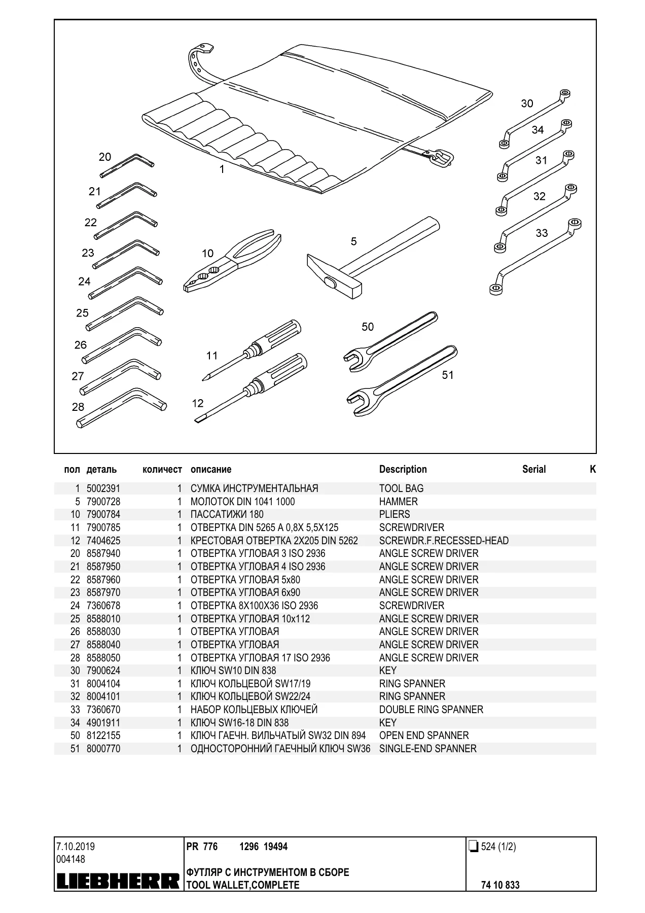
Tool equipment (11 38 539 2) lists the tool wallet with its inserts and sockets, the hammer, pliers, screwdrivers, angle screwdrivers, ring spanners, open end spanners, double-headed spanners, cross handle, extension and socket for spanner, the lever-type hand grease gun with its rubber hose and mouth piece, the oil drain hose, the drain hose and the scavenging duct fat. A second tool equipment entry adds the combination of hand grease gun and key. Service material (11 36 160 5) gathers the service kits: standard 500 h, 1000 h, 1500/2500 h and 2000 h kits, each itemised with the filter inserts (4 µm, 5 µm, 10 µm, 14 µm and 30 µm), fuel filter inserts and pre-assembled filter inserts, cover seals, O-rings, air filter and safety element, recirculation filter, seal kits and the V-ribbed belts that go with them.
Equipment: Blade, Push Frame and Rear Ripper (00 20 000 00)
The shield and shovel group (11 43 242 2) carries the shield mounting components and the high-pressure cutting equipment: cutters, end bit left and right, countersunk screws, washers 34X55X6 and nuts. The push frame and shovel arm group (11 36 527 0) adds the push frame pitch angle, with left and right push frame assemblies, the stanchion, the hydraulic cylinders with their clevis mountings, and the add-on parts that carry the trunnions, pins, holding plates, pressure lines, clamp halves and hoses.
The rear ripper group (11 43 242 2 and 12 43 242 2) describes the single-shank ripper in full: frame, tool bar, washers 120,45 and 120,43, pins 120X368X318, sheets, hex screws, the reference plate, protection covers, hydraulic cylinders for the ripper and the shank, hoses 25X1500 and 25X1400, rectangular section rings and flange halves. The ripper tooth cpl. (11 42 504 8) breaks down into the tooth itself, the tip, the armament and the tooth retaining element with its pin 31,75 and locking rings, and the cold-weather add-on parts group (11 36 403 1) supplies the pin extractor, console, weld plates, clamp halves, lid plates and hoses needed when the machine works in low temperatures.
Why This Catalog Belongs on the Parts Desk
Ordering a component for a crawler dozer without a parts catalog is guesswork, and guesswork on a machine of this size is expensive. A roller is not simply a roller: the PR 776 catalog distinguishes single-flange and double-flange D10N rollers, gives each its own axle, bushing, end piece and seal arrangement, and splits the listing by machine serial where Liebherr changed the design during production. The same discipline runs through the final drives, the hydraulic cylinders, the brakes, the fuel and oil filters, the cab glazing and the ripper. With this catalog open, a technician can quote the exact part number, confirm the quantity, check whether the repair kit is the better buy than the individual components, and hand the parts desk a page and position number instead of a description.
It is equally useful for planning. The service material chapter shows what a 500 h, 1000 h, 1500/2500 h and 2000 h service actually consumes, the filling fluids chapter lists what each circuit takes, and the tool equipment chapter shows which special tools the job calls for. For a workshop running a PR 776 as a working machine, that turns a maintenance stop from a series of surprises into a scheduled list.
Delivery is immediate. The catalog is supplied as a PDF that opens on a laptop, tablet or phone in the workshop office, on the shop floor or in the field, and any page or drawing can be printed for the mechanic doing the job. There is no shipping, no waiting for a paper copy, and no risk of a loose-leaf binder losing the page that matters. Download it once and the complete 1048-page Liebherr PR 776 Type 1296 parts catalog is on hand for as long as the machine is in service.
IMAGES PREVIEW

Reviews
There are no reviews yet.