
Liebherr R914C & R924C Hydraulic Excavator Service Manual – Complete PDF Workshop Download
Original price was: $59.95.$39.95Current price is: $39.95.
Full 876-page Liebherr service manual for R914C and R924C Litronic hydraulic excavators. Covers the D 934 S A6 diesel engine, DPVP 108 twin pump, LR/LS regulation, swing gear, travel gear, track components, electrical system, monitoring display error codes, hydraulic schematics, adjustment check lists, and every major repair procedure with diagrams, exploded views, and torque tables. Instant PDF download.
Description
The Liebherr R914C / R924C Hydraulic Excavator Service Manual is a comprehensive 876-page workshop reference covering the complete R914C and R924C Litronic excavator lines from serial number 19527 (R914C) and 19846 (R924C). This full service manual spans every major system on the machine — from the D 934 S A6 diesel engine and DPVP 108 variable-displacement twin pump through to the swing gear, travel gear, track components, electrical system, and central lubrication circuit. Whether you are performing scheduled maintenance, diagnosing a hydraulic fault, or rebuilding a hydraulic cylinder, this manual provides the procedures, specifications, and diagrams needed to get the job done correctly.
File Details
- Manual type: Service Manual
- Brand: Liebherr
- Models covered: R 914 C, R 924 C
- Engine model: D 934 S A6
- Language: English
- Page count: 876 pages
- File format: PDF
Chapters Covered
- General information
- Tools
- Technical data / Maintenance guidelines
- Engine / Motor
- Coupling / Splitterbox
- Hydraulic system
- Hydraulic components
- Electrical system
- Swing gear
- Swing ring
- Travel gear
- Track components
- Options
- Cab / Heater / Air conditioning system
- Central lubrication
General Information, Tools, and Technical Data
The opening sections establish the safety framework for the entire manual, including the Danger, Caution, and Note symbol conventions used throughout. The technical data chapter provides operating weights (23,730 to 25,935 kg for R914C; 26,170 to 28,340 kg for R924C), digging forces, breakout forces, and drawbar ratings, alongside maintenance schedules and lubrication charts. The tools section covers Liebherr special tooling, including measuring devices, piston nut wrenches, compression devices, and slipring seal installation tools.
Engine / Motor — D 934 S A6
The engine chapter covers the Liebherr D 934 S A6 turbocharged four-cylinder diesel. Technical data includes a 122 mm bore, 136 mm stroke, 6.36-litre displacement, and 17.0:1 compression ratio with a firing order of 1-3-4-2. Power ratings are 115 kW (157 hp) for the R914C and 130 kW (177 hp) for the R924C at 1800 rpm. Maximum torque is listed at 760±10 Nm (R914C) and 820±10 Nm (R924C) at 1500 rpm. Valve clearance settings — 0.30 mm intake and 0.40 mm exhaust when cold — are provided together with oil pressure specifications and coolant system data. The diesel particle filter accessory kit is also documented, including backpressure monitoring, regeneration procedure, and the data logger system.
Coupling and Splitterbox
The torsional vibration damper (elastic coupling) installation between the D 934 S A6 and the pump splitterbox is covered with both removal and reinstallation procedures. The pump distribution gear chapter describes the spur gear unit that transfers engine power to the hydraulic pumps, including gear ratios, oil capacities, and lifting weights for the complete pump assembly.
Hydraulic System and Hydraulic Components
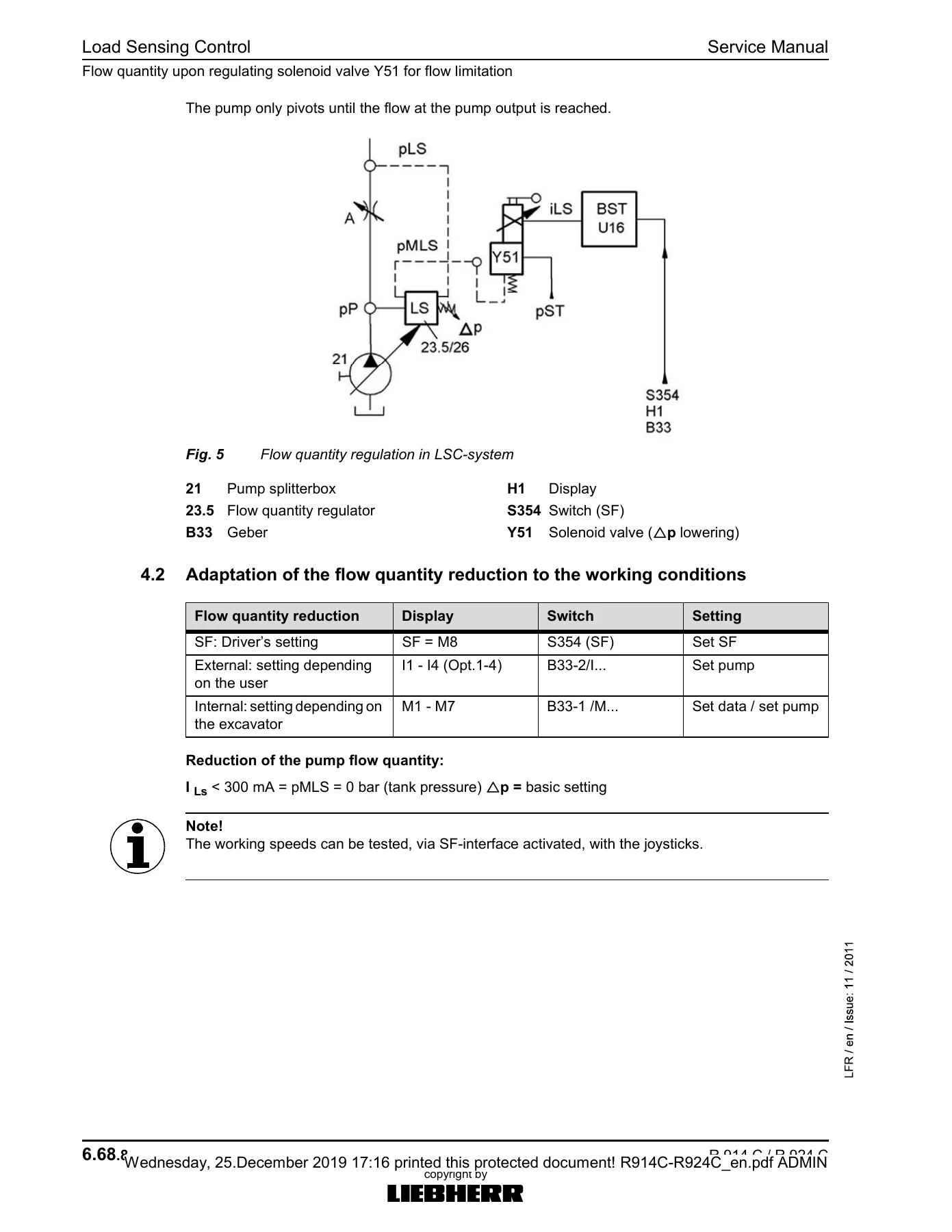
This is the largest section of the manual. It opens with the Load Sensing Control (LSC) system explanation covering flow regulation, power control, and the interaction between the solenoid valves Y50 and Y51. The hydraulic layout chapter describes the tank arrangement, DPVP 108 variable-displacement twin pump, gear pumps for servo and fan drive, control valve block, oil cooling circuit, and oil feeder pipe. The components list runs across the full hydraulic schematic, identifying every numbered valve, piston, and connection. The hydraulic components group then provides removal, installation, and start-up procedures for the variable-displacement pump and gear pump, followed by a deep dive into the DPVP twin pump: its power train, pump adjustment, shuttle valve, LR/LS regulation, and the SD-axis pressure difference regulation.
Electrical System
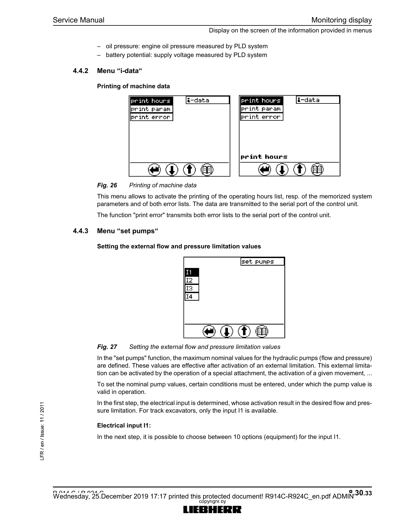
The electrical section documents the cab control elements, monitoring display H1, control unit S2 (BBT), print plate A1001 and A1010, fuse assignments, relay functions, and error code list. The monitoring display chapter details the analog gauges, indicator lights, LCD screen menus, and error codes from E 002 through E 894. The control unit S2 chapter covers the coding plug function, memory storage, and the replacement procedure for the BBT. PRS software uploading via LIDIS is also documented.
Swing Gear, Swing Ring, Travel Gear, and Track Components
The swing gear (SAT 275/237 for R914C, SAT 275/238 for R924C) is documented with construction details, technical data, torque transmission, gear lubrication, and sealing procedures. The swing gear brake section explains the multi-disc brake, solenoid valve Y7, and brake repair. The ball slewing ring chapter covers the KUD 64 VJ 003-001 bearing with tilting clearance measurements, circumferential backlash measurement, dismantling, and installation. The travel gear chapter covers the FAT 350 P022 with three planetary stages, and the travel brakes including the multi-disc brake and brake valve 205. Track components are covered with wear limits for chains, rollers, guide wheels, and sprockets, plus procedures for dismantling and installing carrier rollers, track rollers, and complete chains.
Options, Cab / Heater / Air Conditioning, and Central Lubrication
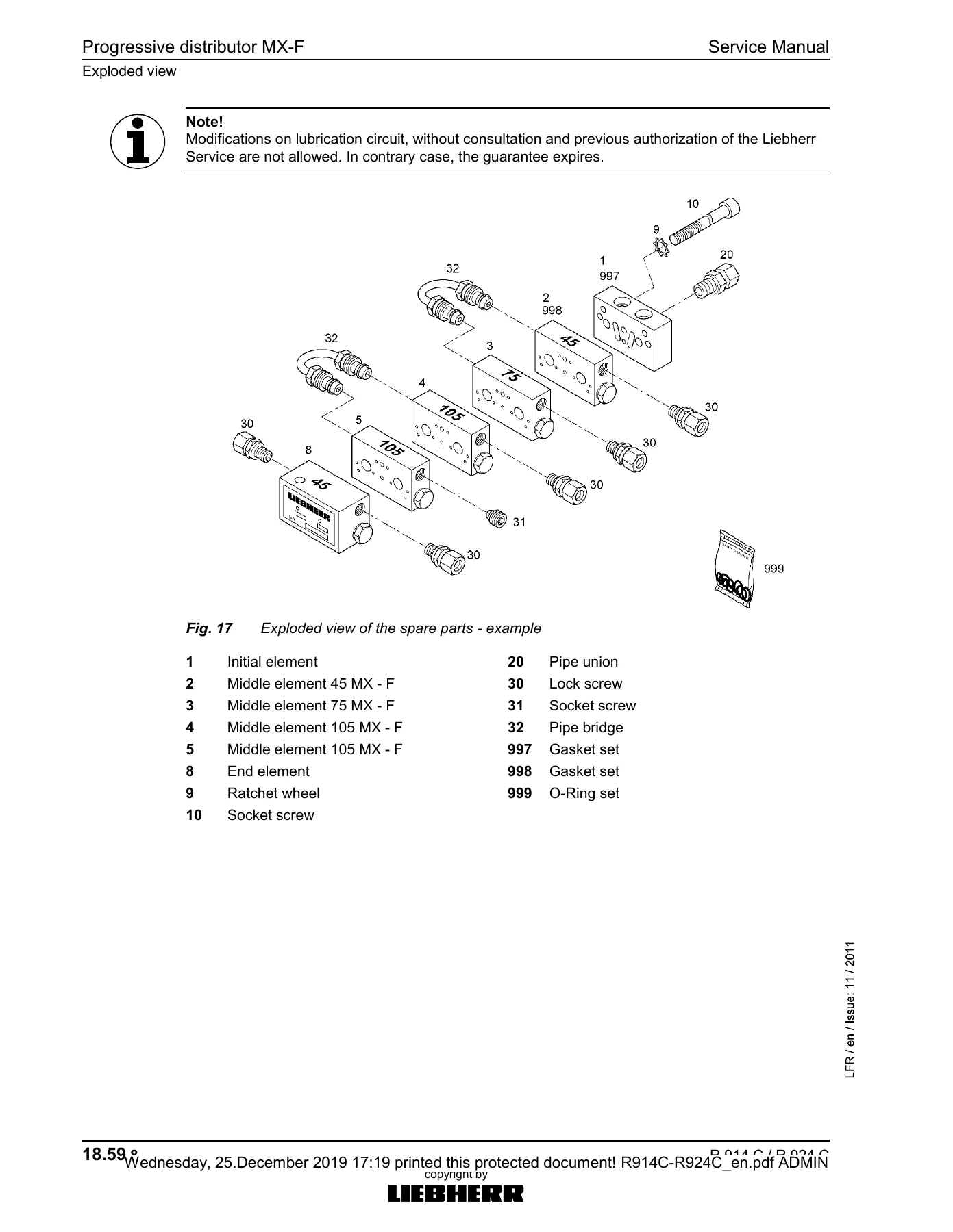
The options chapter documents load holding valves for hoist cylinders, hydraulic installation kits AHS 11 and AHS 12 with Tool Control, and the refuelling pump. The cab group covers the auxiliary heating (D 5 W S), heating and air-conditioning system with refrigerant R134a, and the full test menu for the climate control unit. Central lubrication covers the progressive distributor SX-E and MX-F, the electric lubrication pump with EP-tronic controller, and the lube hose repair procedure.
Adjustment Check Lists and Maintenance Schedules
Two complete adjustment check lists are included — one for the R 914 C Li from serial number 19527 and one for the R 924 C Li from serial number 19846. These lists walk through basic adjustments, test conditions, servo pressure settings, horsepower regulation current and pressure values in modes L, F, E, and P, hydraulic regulation begin pressure, pressure difference adjustment, diesel engine output power test, secondary pressures, cut-off pressure, lowering speed settings, swing motor pressures, travel speed, and cooler fan RPM. The control and maintenance chart provides the full scheduled maintenance table for both machines, covering diesel engine and splitterbox, hydraulic system, electrical system, swing gear transmission, ball swing ring, travel gear, tracks, cab and heating, air-conditioning system, and undercarriage/uppercarriage/attachment lubrication.
What You Can Do With This Liebherr R914C R924C Service Manual
This is not a generic overview — it is the same service documentation used by technicians to keep these machines running. With the complete R914C R924C workshop manual in hand, you can:
- Perform engine valve clearance adjustments with the exact cold settings (0.30 mm intake / 0.40 mm exhaust).
- Diagnose hydraulic faults using the adjustment check list values for horsepower regulation, servo pressure, secondary pressures, and cut-off pressures.
- Set the swing motor secondary pressure relief valves to 260±10 bar maximum and 120±5 bar basic.
- Measure track chain wear against the published limits for B60L Intertrac KN 461 and D6C Berco LH1348 chains.
- Troubleshoot the monitoring display error codes E 002 through E 894.
- Replace the swing gear brake discs without removing the entire gear from the machine.
- Refill travel gear oil, track roller oil, and carrier roller oil to the specified quantities.
- Set the fan drive speed via solenoid valve Y347 and diagnose the hydraulic fan control circuit.
- Interpret the load-sensing flow-control schematic and understand how the DPVP pump responds to user demand.
Why Correct Procedures and Specifications Matter
Liebherr excavators are precision-engineered machines, and the R914C and R924C are no exception. The hydraulic system runs at pressures up to 400 bar, and the swing motor secondary pressures reach 260 bar. Torque specifications for critical fasteners — such as the 560 Nm slewing ring screws and the piston nut tightening values in the torque table — must be followed precisely. The manual provides the torque tables, adjustment values, and measurement procedures that prevent damage and ensure long service life. Whether you are adjusting the horsepower regulation to match the engine’s output, measuring the tilting clearance of the swing ring, or setting the lowering throttle dimensions on the boom and stick, this manual gives you the reference values you need.
IMAGES PREVIEW
Instant PDF Delivery — No Shipping, No Waiting
The Liebherr R914C R924C hydraulic excavator service manual is delivered as an instant PDF download after payment. There is no physical book to ship, no waiting for delivery, and no risk of a damaged package. The file works on any device — laptop, tablet, or smartphone — and can be printed page by page for use in the workshop. Every diagram, exploded view, hydraulic schematic, and specification table is preserved exactly as it appears in the original manual, so you get the full reference material without compromise.
Reviews
There are no reviews yet.