
SANY SY215 (Stage Ⅱ) Hydraulic Excavator Service Manual PDF Download
Original price was: $79.95.$47.95Current price is: $47.95.
The SANY SY215 (Stage Ⅱ) hydraulic excavator service manual provides 1,198 pages of repair, diagnostic, test, adjustment, removal/installation, hydraulic, electrical and schematic information for the SY215 (Stage Ⅱ) with SANY Power D06S2T1 engine.
Description
SANY SY215 (Stage Ⅱ) Hydraulic Excavator Service Manual Scope
Spanning 1,198 PDF pages, this SANY SY215 (Stage Ⅱ) hydraulic excavator service manual is a workshop reference for the maintenance, diagnosis, adjustment, removal, installation, disassembly and assembly work documented for the SY215 (Stage Ⅱ). The manual identifies the machine as a crawler hydraulic excavator and states that it was prepared for experienced technicians who need technical information for maintenance and repair. Its coverage runs from basic service standards and safety through machine specifications, hydraulic and electrical operating principles, standard values, testing, fault diagnosis, component-level repair procedures, and complete-vehicle hydraulic, electrical and harness diagrams.
What You Receive
- Manual type: Service / Workshop / Repair
- Brand: SANY
- Machine: SY215 (Stage Ⅱ) hydraulic excavator
- Engine identified in the technical specifications: SANY Power D06S2T1
- Language: English
- Length: 1,198 PDF pages
- File format: PDF
- Manual identification shown throughout: Service Manual-9-2023
Machine, Engine and Configuration Coverage
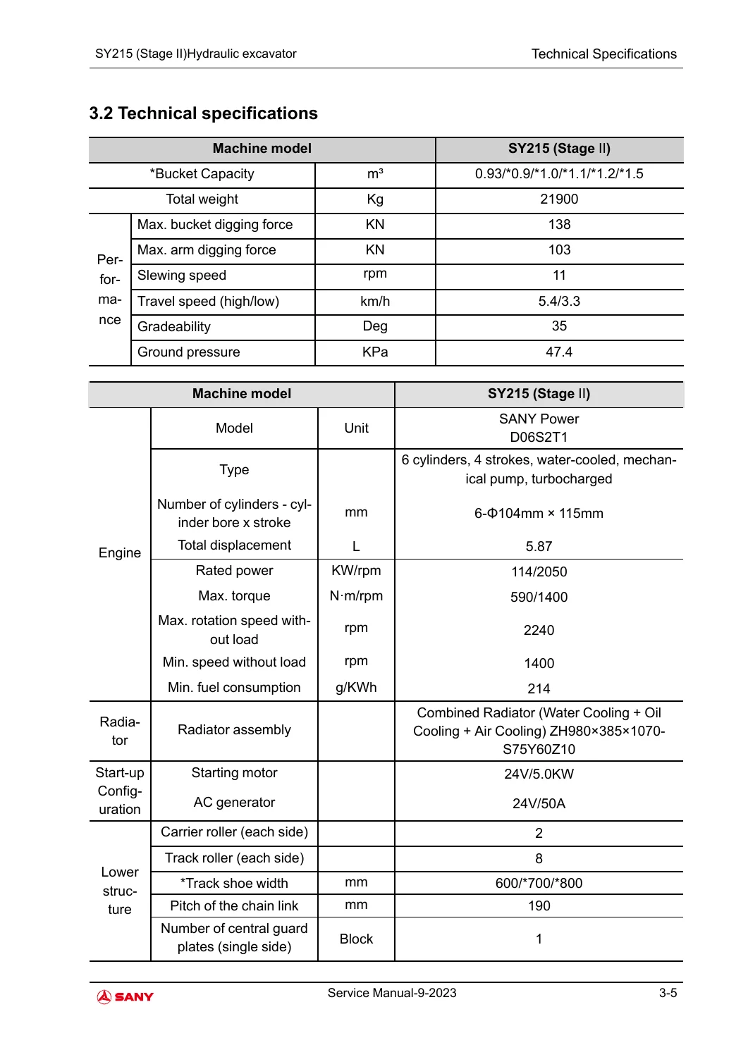
The model named throughout the document is SY215 (Stage Ⅱ). The technical specification chapter identifies the engine as SANY Power D06S2T1, described as a 6-cylinder, 4-stroke, water-cooled, mechanical-pump, turbocharged engine with 5.87 L displacement. The same specification pages show a rated power of 114 kW at 2050 rpm and maximum torque of 590 N·m at 1400 rpm. The manual also records optional bucket capacities of 0.9, 1.0, 1.1, 1.2 and 1.5 m³ alongside the 0.93 m³ value, and track shoe widths of 600 mm with 700 mm and 800 mm optional configurations. No serial-number range or production-year range is clearly stated in the manual, so none is added here.
Contents Organized by the Manual’s 11 Main Chapters
- 1 Foreword
- 1.1 Methods of Reading the Service Manual
- 1.2 Description of maintenance standard terms
- 1.3 Handling of electrical components and hydraulic components
- 1.4 Pipe connector
- 1.5 Bolt and nut
- 1.6 Maintenance of split flange
- 1.7 Conversion table
- 2 Safety
- 2.1 Safety signs
- 2.2 General Precautions
- 2.3 Preparation work before repair
- 2.4 Precautions for Maintenance
- 2.5 Other precautions
- 3 Technical Specifications
- 3.1 Specified Dimension Drawing
- 3.2 Technical specifications
- 3.3 Weight Table
- 3.4 Engine oil, fuel and coolant
- 4 Structure and function
- 4.1 Engine and cooling system
- 4.2 Power train
- 4.3 Dismounting traveling device
- 4.4 Working device
- 5 Hydraulic system
- 5.1 Operation principle
- 5.2 Working principle of hydraulic components
- 6 Electrical system
- 6.1 Control function
- 6.2 Operating principle of elements
- 6.3 Air conditioning system
- 6.4 Engine control
- 6.5 Display system
- 7 Standard values of components
- 7.1 Standard value table of engine related parts
- 7.2 Standard value table of vehicle body related parts
- 8 Test and Adjustment
- 8.1 Engine speed inspection and calibration
- 8.3 Adjustment of valve clearance
- 8.4 Inspection and adjustment of injection timing
- 8.5 Measurement of oil pressure
- 8.9 Slewing bearing clearance measurement
- 8.11 Inspection and adjustment of hydraulic oil in the hydraulic circuits of the working device, slewing, and travel
- 8.12 Check and adjustment of the control oil circuit pressure
- 8.18 Measurement of oil leakage amount
- 8.20 Traveling deviation measurement
- 8.21 Monitoring item table
- 9 Fault diagnosis and exhaust
- 9.1 Precautions during fault diagnosis
- 9.2 Work procedures during fault diagnosis
- 9.3 Inspection before fault diagnosis
- 9.4 Categories and steps of fault diagnosis
- 9.5 Fault diagnosis when the current fault code is displayed
- 9.6 Fault diagnosis of electrical system (E fault category)
- 9.7 Fault diagnosis of hydraulic system and mechanical system (H mode)
- 9.8 Fault type and troubleshooting method
- 10 Removal and installation
- 10.3 Removal and installation of hydraulic system
- 10.4 Removal and installation of swing mechanism
- 10.5 Power System-Remove and Install
- 10.6 Removal and installation of travel device
- 10.7 Removal and installation of main valve
- 10.8 Removal and installation of working device
- 10.9 Removal and installation of electrical system
- 10.10 Cab-Remove and Install
- 10.11 Air Conditioning System-Remove and Install
- 10.12 Covering Parts-Remove and Install
- 10.13 Disassembly and Assembly of Counterweight Assembly
- 11 Hydraulic and electrical schematic diagram
- 11.1 Hydraulic schematic diagram
- 11.2 Electrical schematic diagram
- 11.3 Wire harness diagram
Hydraulic, Electrical and Machine-System Detail
The hydraulic material goes beyond a simple circuit overview. It explains boom, arm, bucket, travel, slewing, oil-return and pilot hydraulic systems, then moves into individual components including the hydraulic cylinders, oil tank and filter, main control valve, hydraulic pump, accumulator, traveling motor, swing motor, pilot valves, center swivel connector, regulator, pilot filter, six-way solenoid valve unit and safety valve. The specification section identifies a Kawasaki K3V112DTP1N9R-0E11-AV hydraulic pump with a maximum main-pump flow of 2 x 220 L/min and a 34.3 MPa main relief pressure. It also identifies the Kawasaki KMX15RB/B45201H-V control valve, SM8V180PHS traveling motors and M5×130CHB-10A-5GA/260 slewing motor.
The electrical chapter explains engine-pump compound control, pump and valve control, travel dual-speed control, automatic idle/acceleration control, secondary boost, separator-water alarm logic, engine preheating and overheating alarm logic, key switch and starter motor operation, air-conditioning controls, engine control and the display system. The final schematic chapter then provides hydraulic circuit material, the complete-vehicle electrical schematic, controller and power-supply circuits, start-control and communication material, plus control-switch, vehicle-body and cab harness diagrams.
Specifications and Service Reference Values
The manual provides dimensional, performance, weight, capacity and service-standard data that can be checked before adjustment or repair. Overall transport length is 9680 mm; transport height is 3440 mm; cab-top height is 3075 mm; standard overall width is 2980 mm with the 600 mm track configuration. Operating-range data includes a maximum digging height of 9600 mm, dumping height of 6730 mm, digging depth of 6600 mm, vertical digging depth of 6255 mm and maximum digging distance of 10280 mm. Machine weight is listed as 21900 kg, maximum bucket digging force as 138 kN, maximum arm digging force as 103 kN, slewing speed as 11 rpm, travel speed as 5.4/3.3 km/h and gradeability as 35 degrees.
Capacity data includes 22 L for the engine oil pan, 4 L for the slewing mechanism case, 5.5 L x 2 for the final-drive cases, 220 L for the hydraulic oil tank, 29 L for the cooling system and 340 L for the fuel tank. The standard-values and test chapters add measurable criteria such as valve clearances, compression pressure, engine oil pressure, belt tension, engine speed, hydraulic pressures, slide-valve stroke, movement times, leakage limits and travel deviation. These values are paired with measuring conditions so the technician can compare machine behavior with the manual’s new-machine standards and allowable or maintenance limits.
Diagnostics, Fault Codes and Repair Operations
The fault-diagnosis chapter contains current fault-code procedures for E001, E002 and E004 through E008, followed by hydraulic-related H codes from H001 through H037 with specific numbers omitted where the manual does not list a code. The H-code entries cover pilot-pressure signals, hydraulic oil temperature, front and rear pump pressure, temperature sensing and proportional-valve current conditions. Separate symptom-based tables run through electrical faults E-1 to E-26 and hydraulic/mechanical faults H-1 to H-24, addressing conditions such as no-start, irregular engine speed, failed auto-idle, powerless boom/arm/bucket or travel movement, display problems, inaccurate pressure indications, abnormal pump noise, travel deviation, steering weakness and slewing faults. A further troubleshooting section addresses whole-machine power loss, no movement, air-conditioning failure, arm drop, black smoke, one-side travel weakness and failure to speed up.
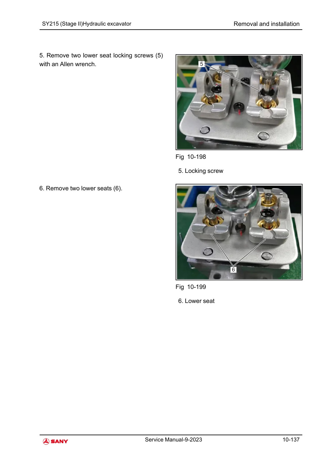
Chapter 10 supplies component-level removal, installation, disassembly and assembly work. Coverage includes hydraulic cylinders and pump, filters, solenoid valves, swing motor and swivel joint, fuel and cooling systems, engine-related assemblies, duplex pedal valve, final drive, pilot valves, rollers and track assembly, main valve, boom/arm/bucket linkage, controller and electrical parts, cab components and the air-conditioning system. The engine section includes cylinder-head, oil-seal, fuel-injection-pump, starter-motor and camshaft/rocker procedures, while the foreword explains that specialized tools, tightening torque, coating materials, engine oil, grease and coolant information are incorporated where required.
Use the Correct Data at the Machine
Working from the correct SY215 (Stage Ⅱ) figures and procedures keeps diagnosis, adjustment and component work tied to the data printed for this machine instead of improvised values. From that reference point, a technician can trace hydraulic and electrical faults, compare measured results with the listed standard values, adjust engine and hydraulic parameters, follow circuit paths, and use the documented removal and assembly sequences for major systems. The PDF becomes available as an instant download as soon as payment completes, with no shipping or waiting; it can be opened on a phone, tablet, laptop or workshop PC and printed for bench-side reference.
Reviews
There are no reviews yet.