★ TRUSTED BY 321,897+ PROFESSIONALS WORLDWIDE
🏒
Trusted Business
Verified & Licensed
πŸ›‘οΈ
Virus Free Files
100% Safe Downloads
πŸ”’
Secure Payment
SSL Protected
⚑
Instant Delivery
Available Immediately
Sale!

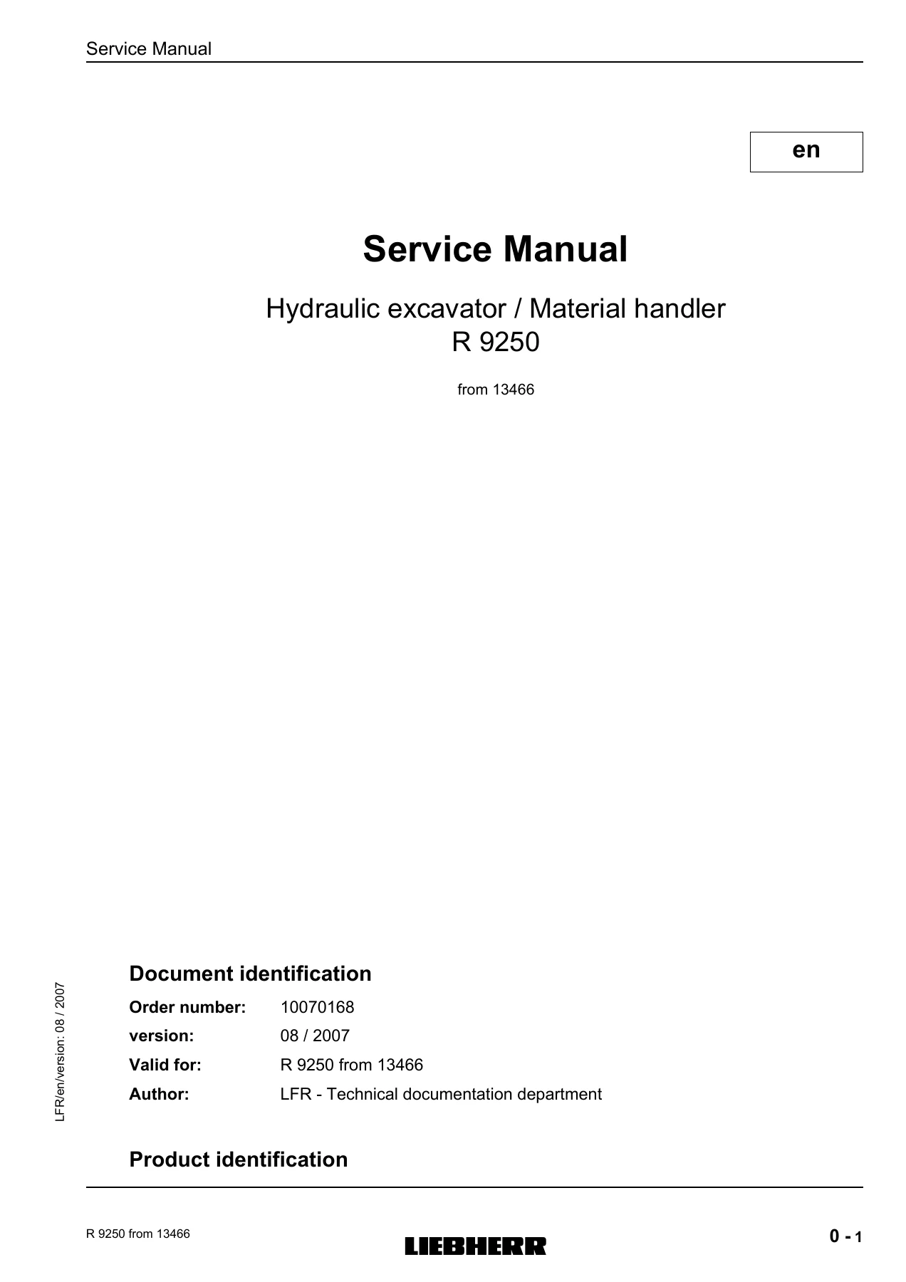
Liebherr R9250 Hydraulic Excavator Service Manual 2007 – 10070168

Original price was: $44.95.Current price is: $26.95.

Complete Liebherr service manual for the R 9250 hydraulic excavator and material handler, document 10070168, edition 08/2007, valid from serial number 13466. Full hydraulic, engine, swing, electrical, cooling, track and uppercarriage mechanical coverage across 972 pages.

⚑
Instant PDF Download
Available immediately
πŸ’Ύ
Save to Your Device
Download & keep forever
πŸ›‘οΈ
Antivirus Scanned
100% virus-free
🌍
Trusted Worldwide
175,000+ customers

Description

Complete Liebherr R9250 hydraulic excavator and material handler service manual, document order number 10070168, edition 08/2007, valid for machines from serial number 13466. This 972-page workshop manual covers every major system on the R 9250, from the Cummins QSK 45 diesel engine and splitterbox through the working pumps, control valve blocks, swing system, cooling circuits, track tensioning, electrical system and uppercarriage mechanical assembly. Written by LFR Technical Documentation for Liebherr France SAS, it is the reference document technicians use for adjustment, diagnosis, repair and rebuilding of this 960 kW (1304 HP) excavator.

File Details

  • Manual type: Service manual / workshop manual
  • Brand: Liebherr
  • Model: R 9250 (type no. 437)
  • Document order number: 10070168
  • Edition / version: 08 / 2007
  • Valid for: R 9250 from serial number 13466
  • Language: English
  • Page count: 972 pages
  • File format: PDF
  • Author: LFR – Technical documentation department
  • Manufacturer: Liebherr France SAS, Colmar Cedex

Chapters Covered

  • Chapter 1 – General: safety information and signage, tightening torques (metric, SAE fittings, hexagon socket head cap screws), HYTORC torque machine operation, welding procedures, electrode classification, reinforcement plates
  • Chapter 2 – Safe work procedure / Risk assessment: 38 individual SWPs including machine isolation, hydraulic repair isolation, engine removal, track component isolation, welding repair isolation, hydraulic cylinder removal, bucket and link removal, suction valve repair, load roller replacement, track chain replacement, track drive sprocket change, counterweight removal, boom removal, stick removal, splitterbox input shaft, idler replacement, carrier roller, bucket change, work pump, cabin, swing box, main valve bank, swing pump, splitterbox gears, HYTORC operation, centre girder and side frames, boom fitment, uppercarriage assembly, undercarriage assembly, faceshovel/backhoe assembly
  • Chapter 3 – Technical Data: machine weight, engine data (Cummins QSK 45), splitterbox, hydraulic system (main circuit, swing circuit, servo control oil circuit, cooling circuit), adjustment procedure 9250 (initial adjustment, working pumps, primary and secondary valves, ladder and service trap, swing, cooling)
  • Chapter 4 – Operating / Maintenance: lubrication chart, service trap, control and maintenance chart, oil sampling procedure (splitterbox, engine)
  • Chapter 5 – Tooling: hydraulic, general, electric tooling; special wrench for cylinder piston; mounting device for swing gear brake; slotted nut tools; pump control box installation for R/P 996, 995, 9250 and 9350
  • Chapter 6 – Engine: technical data, cooling system (schematic, function, coolant capacity, cleaning, antifreeze and corrosion protection), fuel system (schematic, capacity, draining condensation, filter change, bleeding)
  • Chapter 7 – Attachment / Travel system: hydraulic pump assembly, functional description, working pumps A20 VSO 520 and A11 VLO 260, pressure cut-off, power regulation, flow limitation, attachment function (boom, stick, bucket tilt, shovel tilt, shovel flap), travel, troubleshooting, adjustment, control valves 4 MO 40 and 4 MO 32, hydraulic cylinders, primary and secondary pressure relief valves, suction valve, geared pump, joystick and pedal transmitters, FSG plate A1020
  • Chapter 8 – Swing system: swing pumps A4 VG 125, swing motors FMF 250, swing gears SAT 450/257, swing ring, functional description, troubleshooting, adjustment, detailed component description
  • Chapter 9 – Cooling system: hydraulic and electric schematics, component location, functional description, temperature regulation, troubleshooting, adjusting, hydraulic pump A11VO75DRX, hydraulic fixed displacement motor FMF 90
  • Chapter 10 – Grease systems: Lincoln centralized lubrication system, hydraulic drum pump, injectors SL-1 and LM-5, progressive metering devices SSV, ultrasonic sensor, digital pressure switch, piston detector
  • Chapter 11 – Ladder / Service trap systems: schematics, component location, functional description (electrical and hydraulic), troubleshooting, pressure control valve adjustment, electro-hydraulic gear pump, rotating cylinder, hydraulic cylinder removal, pressure relief valve, solenoid valve
  • Chapter 12 – Hydraulic track tensioning system: description, function, temperature-dependent pressure adjustment
  • Chapter 13 – Electric systems: main components location, cabin electric, switching box E1005, washer/wipers, analog monitoring, lighting, power pack, engine start and prelub, RPM control, sensors, emergency stop, solenoid valves, alternator and battery, display/sensors, BST, CAN BUS, BBT, components
  • Chapter 14 – Pneumatic control: technical data, pneumatic schematic, component location, functional description, troubleshooting, adjustment, pressure regulator, air dryer, check valve
  • Chapter 15 – Uppercarriage mechanical: coupling, splitterbox GFC 320/1002, swing gear SAT 450/257, swing bearing ROD 1304 DJ, engine / splitterbox mounting, preassembled modules (rotating deck, counterweight, cab, powerpack, hydraulic tank, fuel tank, cab elevation, catwalk boxes)
  • Chapter 21 – Schematics: electrical diagrams, hydraulic schematics

Across its 972 pages this service manual delivers the complete technical picture of the R 9250. Every hydraulic circuit is documented – the two A20 VSO 520 working pumps, the single A11 VLO 260 pump, the A4 VG 125 swing pumps, the A11VO75DRX cooling pumps, the geared servo and lubrication pumps – with adjustment values, test points and troubleshooting flowcharts. The 4 MO 40 and 4 MO 32 control valve blocks are broken down to component level, with leak oil specifications, secondary and primary valve setting procedures, spool removal and resealing. The Cummins QSK 45 engine chapter covers cooling, low-temperature aftercooling (LTA), fuel, and the two-circuit cooling system with capacities. The electrical chapter documents every board – FSG A1020, ESP01 A1001, A1016 interface, A1019 regulation, BST U16 – through to the CAN BUS and BBT, including the display error code list (E501 to E598). The mechanical chapter covers the swing ring bearing, gear pinion backlash, swing gear sealing, and bolt tensioning values for M36 and M42 mounting bolts.

Because this is the manufacturer’s own service documentation, every adjustment value, tightening torque, pressure setting and clearance is presented exactly as the workshop floor expects it. That is what separates a working service manual from a generic repair book – the R 9250 is a large machine with hydraulic pressures up to 380 bar, cylinder screw torques up to 3200 Nm, swing ring bolt tensioning at 1350 bar, and Cummins engine settings that cannot be guessed.

What This Manual Lets You Do

With the Liebherr R9250 service manual on hand a qualified technician can:

  • Carry out the complete initial adjustment sequence for the R 9250 – servo pressure at 55 bar, swing brake at 30 bar, working pump flow switching point, Qmin/Qmax hydraulic settings, power regulator LR, pressure cut-off DR, and the primary and secondary valve pressures on all four control valve blocks
  • Remove and reinstall the engine, splitterbox, main pumps, swing pumps, swing gear, counterweight, boom, stick, bucket, travel gears, track chains, load rollers, idlers, carrier rollers and the cabin following the SWP (Safe Work Procedure) steps
  • Diagnose and repair hydraulic faults across the attachment, travel, swing, cooling and grease circuits using the supplied troubleshooting charts, test points and leak oil measurement procedures
  • Reseal hydraulic cylinders with either new-fixation or old-fixation pistons, including the correct seal orientation for rod step seals, glyd rings and support rings, plus the tightening torques for the piston and bearing head screws
  • Service the Cummins QSK 45 diesel engine cooling system, LTA aftercooling circuit, fuel filters and the bleed procedure
  • Set up the Lincoln centralized lubrication system – pump cycle times, grease quantities, injector output adjustment, SSV progressive divider diagnosis and blockage location
  • Work through the electrical system with the correct fuse and relay assignments, connector pin-outs, CAN BUS layout, Quantum and BST error codes, and emergency-stop wiring
  • Adjust the ladder and service trap circuits including the pressure control valve at 110 bar, and diagnose the safety interlock that prevents machine operation unless both are locked in the upper position
  • Rebuild the track tensioning system – the elastomer tensioner pressure curve from -20 degrees C to +50 degrees C and the correct filling/reducing procedure
  • Check and tension the swing ring bearing bolts with the bolt tensioning cylinder procedure, measure axial, radial and backlash play and compare against the wear limits

Why It Matters

The R 9250 is a 250-tonne class machine. Wrong hydraulic pressure settings, incorrect cylinder torque values or mis-tensioned swing ring bolts do not fail gently – they damage pumps, cylinders, bearings and structural components. The pressures, clearances and torque figures in this manual are the ones that keep the excavator inside its design envelope. Having the actual Liebherr settings at the bench means the difference between a repair that holds and a repair that comes back.

Complete PDF Bookmark Tree

Complete Bookmarks

The complete bookmarks in the β€œLiebherr R9250 Hydraulic Excavator Service Manual 2007 – 10070168” are as follows:

1 Generalp. 7
1.1 Safety information, signagep. 7
1.1.1 Symbols in the operating instructionsp. 7
1.1.2 Use in accordance with the regulationsp. 8
1.1.3 Safety instructionsp. 8
1.1.3.1 General safety instructionsp. 8
1.1.3.2 Avoidance of crushing and burnsp. 9
1.1.3.3 Avoidance of fire and explosionsp. 10
1.1.4 Servicing the machine safelyp. 10
1.1.4.1 General safety instructionsp. 10
1.1.4.2 Cleaningp. 11
1.1.4.3 Crack testingp. 11
1.1.4.4 Welding, drilling, firing and grinding workp. 12
1.1.4.5 Process materialsp. 12
1.1.5 Repair workp. 12
1.1.6 Electrical systemp. 13
1.1.7 Hydraulic accumulatorp. 13
1.1.8 Hydraulic hoses and sheathed cables.p. 14
1.2 Tighteningp. 16
1.2.1 Tightening torquesp. 16
1.2.1.1 Factory standards WN 4037 – Tightening forces and torques of metric screwsp. 16
1.2.1.2 Torque values for the mounting screws on the SAE fittingsp. 18
High pressure fittingsp. 18
Low pressure half flangesp. 19
1.2.1.3 Hexagon – socket – head cap screwp. 19
1.2.1.4 Notesp. 20
1.2.1.5 Wrench size for metric screwp. 20
1.2.2 Hytorcp. 21
1.2.2.1 Safetyp. 21
1.3 Weldingp. 44
1.3.1 Electrical isolation prior to weldingp. 44
1.3.2 Welding proceduresp. 44
1.3.2.1 Preparation of a crackp. 44
1.3.2.2 Preparation of the weldp. 44
1.3.2.3 Classification of the welding electrodesp. 45
1.3.2.4 Storing electrodesp. 46
1.3.2.5 Welding techniquep. 46
1.3.2.6 Reinforcement of the welding seamp. 47
1.3.2.7 General application of reinforcement platesp. 47
Shape of reinforcement platesp. 47
Plate thicknessp. 47
Plate qualityp. 47
Plate installationp. 48
Plate weldingp. 48
2 Safe work proceduresp. 51
2.1 Safe work procedures SWP 001 – Safety check listp. 53
2.2 Safe work procedures SWP 002 – Basic R 9250 machine isolationp. 54
2.3 Safe work procedures SWP 003 – R 9250 Isolate for hydraulic repairp. 55
2.4 Safe work procedures SWP 004 – remove R 9250 enginep. 56
2.5 Safe work procedures SWP 005 – Isolate machine for track component repairsp. 58
2.6 Safe work procedures SWP 006 – Isolate machine for welding repairsp. 59
2.7 Safe work procedures SWP 007 – Remove and replace hydraulic cylinderp. 60
2.8 Safe work procedures SWP 008 – Removal of bucket levers and linksp. 62
2.9 Safe work procedures SWP 009 – Repair / replacement of suction valvep. 63
2.10 Safe work procedures SWP 010 – Remove and replace load rollersp. 64
2.11 Safe work procedures SWP 011 – Remove and replace track chainp. 66
2.12 Safe work procedures SWP 012 – R 9250 track drive sprocket change outp. 68
2.13 Safe work procedures SWP 013 – Remove counterweightp. 71
2.14 Safe work procedures SWP 014 – Remove boomp. 72
2.15 Safe work procedures SWP 015 – Remove stickp. 74
2.16 Safe work procedures SWP 016 – Change splitterbox input shaft assemblyp. 76
2.17 Safe work procedures SWP 017 – Remove idler and replacep. 77
2.18 Safe work procedures SWP 018 – Change carrier rollerp. 78
2.19 Safe work procedures SWP 019 – Bucket change outp. 79
2.20 Safe work procedures SWP 020 – Change out work pumpp. 81
2.21 Safe work procedures SWP 021 – Change cabinp. 83
2.22 Safe work procedures SWP 022 – R 9250 remove and replace enginep. 84
2.23 Safe work procedures SWP 023 – Remove and replace swing boxp. 86
2.24 Safe work procedures SWP 024 – Change main valve bankp. 88
2.25 Safe work procedures SWP 025 – Change swing pumpp. 89
2.26 Safe work procedures SWP 026 – Change splitterboxp. 90
2.27 Safe work procedures SWP 027 – Change splitterbox Gearsp. 92
2.28 Safe work procedures SWP 028 – Change splitterbox input shaft assemblyp. 93
2.29 Safe work procedures SWP 029 – Hy-torc operationp. 94
2.30 Safe work procedures SWP 030 – Remove and replace centre girder and side framesp. 95
2.31 Safe work procedures SWP 031 – Fit stick assembly to boomp. 100
2.32 Safe work procedures SWP 032 – Assemble uppercarriagep. 102
2.33 Safe work procedures SWP 033 – Assemble undercarriagep. 104
2.34 Safe work procedures SWP 034 – Assemble boom, faceshovel or backhoep. 106
2.35 Safe work procedures SWP 035 – Assemble stick, faceshovel or backhoep. 107
2.36 Safe work procedures SWP 036 – Fit boom assembly to uppercarriagep. 108
2.37 Safe work procedures SWP 037 – Assemble LIEBHERR R 9250p. 110
2.38 Risk assessmentp. 114
3 Technical datap. 121
3.1 Machine datap. 121
3.1.1 Generalp. 121
3.1.2 Enginep. 121
3.1.3 Splitterboxp. 122
3.1.4 Hydraulic systemp. 122
3.1.4.1 Main circuitp. 122
3.1.4.2 Swing circuitp. 123
3.1.4.3 Servo control oil circuitp. 123
3.1.4.4 Cooling circuitp. 123
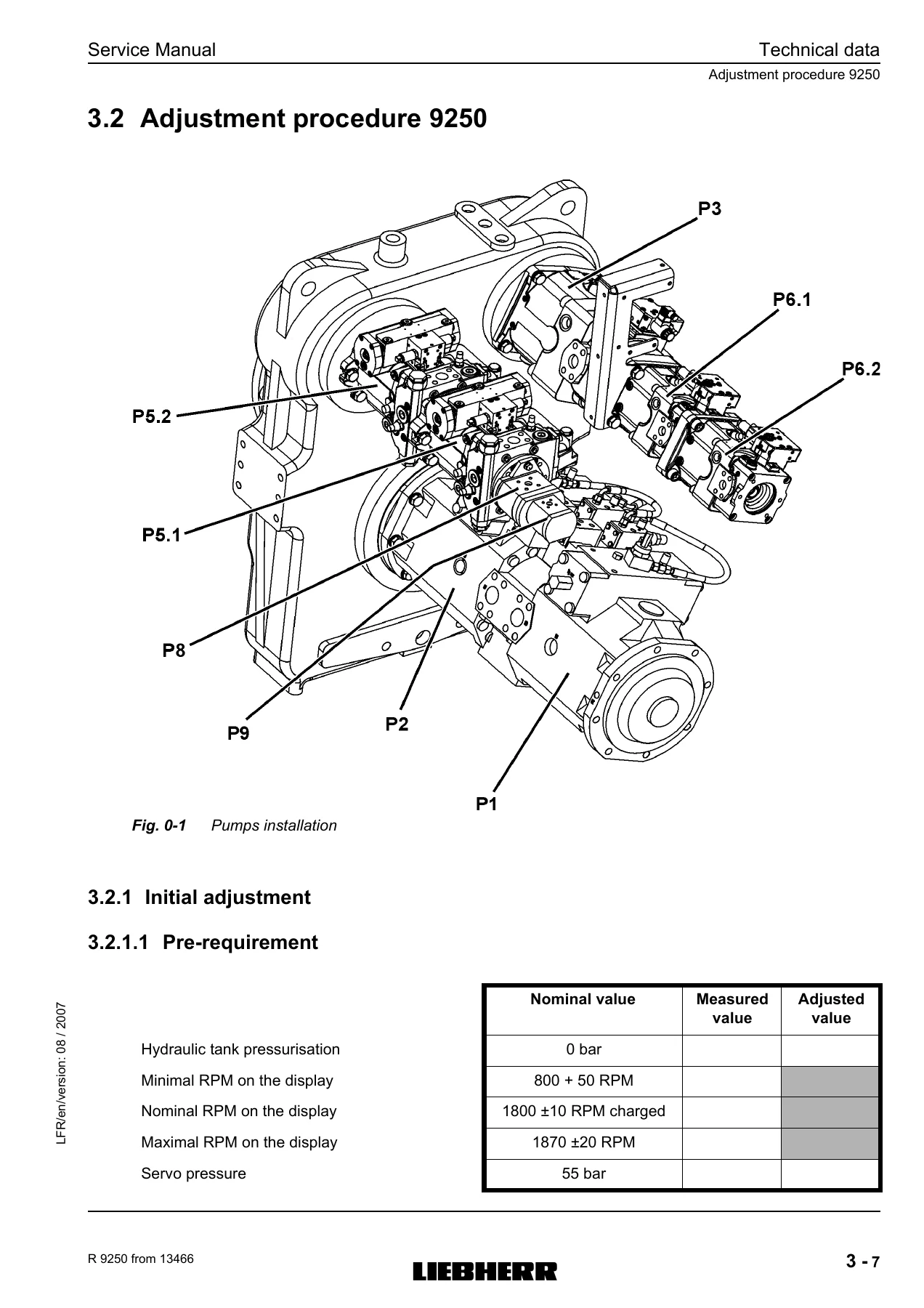
3.2 Adjustment procedure 9250p. 125
3.2.1 Initial adjustmentp. 125
3.2.1.1 Pre-requirementp. 125
Adjustment of servo pressurep. 126
Adjustment of swing brakep. 127
Check of the good working of the pump control boxp. 127
Initial adjustmentp. 128
Installation of the pump control box for R/P 9250p. 128
Pre-adjustment on the displayp. 128
3.2.2 Working pumps adjustmentp. 129
3.2.2.1 Pumps P1 and P2p. 129
Adjustment of switching point for flow controlp. 129
Hydraulic adjustment for Qminp. 130
Hydraulic adjustment for Qmaxp. 130
Adjustment of the power regulatorp. 130
Adjustment of the pressure regulatorp. 131
3.2.2.2 Pump P3p. 131
Beginning of regulationp. 131
Cut off adjustmentp. 132
3.2.3 Primary and secondary valves adjustmentp. 132
3.2.3.1 Secondary valves adjustmentp. 133
Travel adjustmentp. 133
Attachment adjustmentp. 133
3.2.3.2 Primary valves adjustmentp. 135
Simple primary values adjustmentp. 135
3.2.4 Ladder and service trap adjustmentp. 136
3.2.5 Swing adjustmentp. 136
3.2.5.1 Replenishing pressurep. 137
3.2.5.2 Swing working pressurep. 137
3.2.6 Cooling adjustmentp. 138
4 Operating maintenancep. 141
4.1 The lubrication chartp. 143
4.1.1 The service trapp. 143
4.2 Control and maintenance chartp. 145
4.3 Oil sampling procedurep. 151
4.3.1 Oil sample extraction valvep. 151
4.3.2 Splitterboxp. 152
4.3.3 Enginep. 153
5 Toolingp. 157
5.1 Hydraulicp. 159
5.2 Generalp. 177
5.3 Annexesp. 201
5.3.1 Special wrench to remove and install the piston on hydraulic cylindersp. 201
5.3.2 Mounting device for disassembly and assembly of brake housing / disk brake on swing gear Liebherr SAT 220 / 225 / 250 / 275 / 300 / 325 / 350 / 400 /450p. 202
5.3.3 To remove or / and tighten of the slotted nut on the output / swing gear SAT 225 / 250 / 275 / 300 / 325 / 350 / 400 / 450p. 202
5.4 Installation of the pump control boxp. 206
5.4.1 Installation of the pump control box for R/P 996p. 206
5.4.1.1 Connectionp. 206
5.4.1.2 Verification of the flow reduction valuesp. 206
5.4.1.3 Adjustment of the flow reduction values for input 3 and 4p. 207
5.4.2 Installation of the pump control box for R/P 995p. 207
5.4.2.1 Connectionp. 207
5.4.2.2 Verification of the flow reduction valuesp. 207
5.4.2.3 Adjustment of the flow reduction values for input 3 and 4p. 208
5.4.3 Installation of the pump control box for R/P 9250 and 9350p. 208
5.4.3.1 Connectionp. 208
5.4.3.2 Verification of the flow reduction valuesp. 209
5.4.3.3 Adjustment of the flow reduction values for input 3 and 4p. 209
6 Enginep. 249
6.1 Technical datap. 249
6.2 Cooling systemp. 251
6.2.1 Cooling schematicp. 251
6.2.2 Functionp. 253
6.2.2.1 Principal circuitp. 254
6.2.2.2 Low Temperature Aftercooling (LTA) circuitp. 254
6.2.3 Coolant capacityp. 254
6.2.4 Cleaning system and changing antifreezep. 255
6.2.4.1 To drain the coolantp. 256
6.2.4.2 To clean the cooling circuitp. 257
6.2.4.3 To refill the cooling circuitp. 258
6.2.5 Antifreeze and corrosion protection of coolantp. 259
6.2.5.1 Coolant filtersp. 259
6.2.5.2 To change the coolant filtersp. 259
6.3 Fuel systemp. 261
6.3.1 Fuel schematicp. 261
6.3.2 Fuel capacityp. 261
6.3.3 To drain condensationp. 261
6.3.3.1 To drain and clean the fuel tankp. 262
6.3.3.2 Draining and changing fuel filter cartridgesp. 263
6.3.4 Fuel filter changep. 264
6.3.5 Bleeding procedurep. 265
7 Attachment / Travel systemsp. 269
7.1 Schematicp. 269
7.2 Hydraulic pump assemblyp. 271
7.2.1 Technical datap. 271
7.3 Functional descriptionp. 275
7.3.1 Electro-hydraulic systemp. 275
7.3.2 Power circuitp. 276
7.3.2.1 Hydraulik tank and oil filtersp. 276
7.3.2.2 The hydraulic working pumpsp. 276
7.3.2.3 Control valve blocksp. 277
7.3.2.4 Hydraulic oil coolingp. 278
7.3.2.5 Hydraulic rotary connectionp. 279
7.3.2.6 Attachment cylinders and motorsp. 279
7.3.3 Electro-hydraulic pilot control systemp. 280
7.3.3.1 Pilot control unitsp. 280
Mechanical componentsp. 280
Electronic componentsp. 281
7.3.3.2 Servo oil circuitp. 283
Technical datap. 283
Schematic servo oil circuitp. 284
Servo oil circuit : components locationp. 286
Functional descriptionp. 288
7.3.3.3 Logic systemp. 288
Solenoid valves functionp. 289
To read and understand the priority listp. 290
Proximity transmittersp. 292
7.4 Working pumpsp. 296
7.4.1 Descriptionp. 296
7.4.2 Double pump A20 VSO 520p. 296
7.4.2.1 Functionp. 297
Rotary groupp. 297
Pump displacementp. 298
7.4.2.2 Working pump regulationp. 299
7.4.2.3 Pressure cut-offp. 303
Functioning in normal conditionsp. 303
Elevation of the pressure cut-offp. 303
7.4.2.4 Power regulationp. 304
The constant power regulationp. 304
Functionp. 304
Power reduction stagep. 307
7.4.2.5 Flow limitation stagep. 307
7.5 Attachment functionp. 312
7.5.1 Boom cylindersp. 312
7.5.1.1 Boom up movementp. 315
7.5.1.2 Pressureless lower boom cylinderp. 315
7.5.1.3 Boom down movementp. 315
7.5.2 Stick cylinders for backhoe attachmentp. 316
7.5.3 Bucket tilt cylinders for backhoe attachmentp. 318
7.5.4 Shovel tilt cylinders for shovel attachmentp. 320
7.5.4.1 Shovel bucket parellelogram functionp. 322
7.5.5 Shovel flap cylinders for shovel attachmentp. 324
7.6 Travelp. 326
7.6.1 Travel motorsp. 326
7.6.2 Primary pressure relief valve controlled with pilot pressurep. 329
7.6.3 Hydraulic brakingp. 330
7.6.4 Travel brakingp. 331
7.6.5 Travel speed increasep. 332
7.7 Troubleshootingp. 334
7.7.1 Hydraulic cylinder chartp. 334
7.7.2 Extension and retraction time of hydraulic cylinderp. 335
7.7.2.1 Extension time of hydraulic cylinderp. 335
7.7.2.2 Retraction time of hydraulic cylinderp. 335
7.7.2.3 Determination of extension and retraction time with the chartp. 335
7.7.2.4 Examplep. 338
7.7.2.5 Number of pumps and oil flow max for the different movementsp. 338
7.7.3 Control valve block leak oil measurementp. 338
7.7.3.1 Examplep. 339
7.8 Adjustmentp. 341
7.8.1 Adjustment valuesp. 341
7.8.1.1 Excavator’s adjustmentsp. 341
7.9 Component descriptionp. 343
7.9.1 4-ways control valve 4 MO 40p. 343
7.9.1.1 Technical datap. 343
7.9.1.2 Conceptionp. 346
7.9.1.3 Functionp. 346
Spool valves in neutral positionp. 346
Working position of spool valvesp. 346
7.9.1.4 Repairsp. 349
Spool valves 14 and 15p. 349
Replacing regulating springs 20 / 21p. 349
Primary pressure relief valve, pilot operated 28p. 351
Anti-cavitation check valves 29p. 351
Secondary pressure relief valve 30p. 352
Check valve 32p. 353
Proportional pressure reducing valve 34p. 353
3/2 way directional valve 35p. 354
Locking screw 50p. 355
7.9.1.5 Control valve installationp. 355
7.9.1.6 Maintenancep. 355
7.9.2 4-ways control valve 4 MO 32p. 356
7.9.2.1 Technical datap. 356
7.9.2.2 Conceptionp. 358
7.9.2.3 Functionp. 358
Spool valves in neutral positionp. 358
Working position of spool valvesp. 358
7.9.2.4 Repairsp. 360
Spool valves 36, 37, 38 and 39p. 360
Primary pressure relief valve, pilot operated 60p. 363
Control valve 117p. 364
Pressure reducer valve 118p. 365
Suction valve 143p. 366
7.9.2.5 Control valve installationp. 366
7.9.2.6 Maintenancep. 366
7.10 Hydraulic cylinderp. 367
7.10.1 Construction of hydraulic cylindersp. 367
7.10.2 Functionp. 368
7.10.3 Function of hydraulic cylinderp. 368
7.10.3.1 To extend piston rod 8p. 368
7.10.3.2 To retract the piston rod 8p. 368
7.10.4 General maintenancep. 369
7.10.4.1 Anti-rotation protectionp. 369
7.10.4.2 Transportationp. 369
7.10.4.3 Storagep. 370
7.10.4.4 Installationp. 370
7.10.4.5 Start upp. 370
7.10.4.6 Maintenancep. 370
7.10.5 Removal and installation of the hydraulic cylindersp. 371
7.10.5.1 Removalp. 371
7.10.5.2 Installationp. 371
7.10.6 Resealing the hydraulic cylinder with new fixationp. 372
7.10.6.1 Disassemblyp. 372
7.10.6.2 Assemblyp. 373
7.10.7 Resealing the hydraulic cylinder with old fixationp. 375
7.10.7.1 Disassemblyp. 375
7.10.7.2 Assemblyp. 376
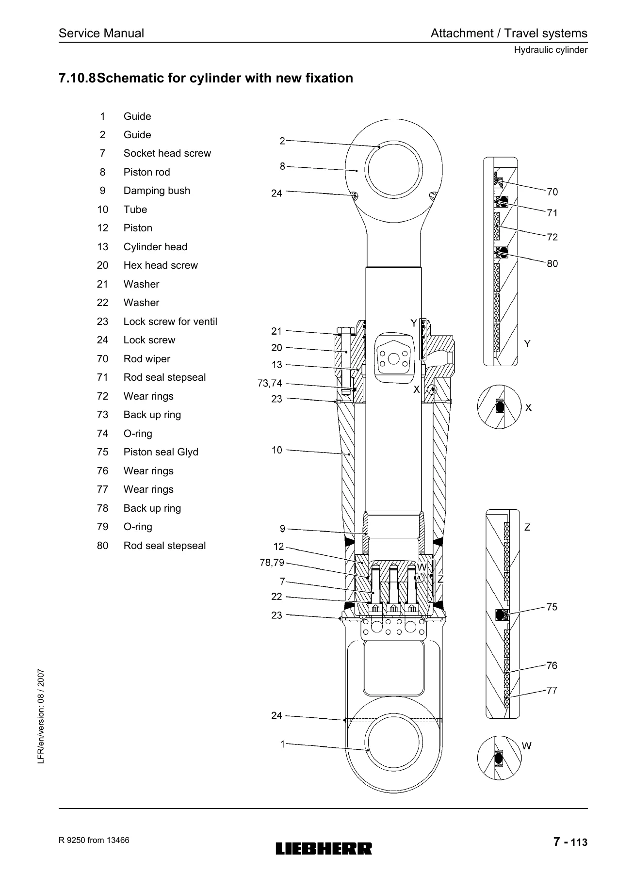
7.10.8 Schematic for cylinder with new fixationp. 379
7.10.9 Schematic for cylinder with old fixationp. 381
7.10.10 Torque values of the mounting screws (new fixation)p. 383
7.10.11 Torque values the piston and the piston nut (old fixation)p. 384
7.11 Primary valve : Pilot operated pressure limiting valvep. 385
7.11.1 Usep. 385
7.11.2 Functionp. 385
7.11.3 Pressure adjustmentp. 385
7.12 Primary valve : Two-stage pilot operated pressure limiting valvep. 387
7.12.1 Usep. 387
7.12.2 Functionp. 387
7.12.2.1 Stage I – Reduced pressurep. 387
7.12.2.2 Stage II – High pressurep. 387
7.12.2.3 Pressure adjustmentp. 387
7.13 Secondary pressure relief valve pilot controlledp. 388
7.13.1 Usep. 388
7.13.2 Functionp. 388
7.13.3 Pressure adjustmentp. 388
7.14 Secondary valve : Two-stage pilot operated pressure limiting valvep. 390
7.14.1 Function of pressure cut offp. 390
7.14.1.1 Stage 2 (normal pressure = high pressure)p. 390
7.14.1.2 Cut off stage or stage 1 (low pressure)p. 390
7.14.1.3 Pressure check and adjustmentp. 390
To check and adjust high pressure (stage 2)p. 390
To check and adjust low pressure (stage 1)p. 391
7.15 Suction valvep. 392
7.15.1 Task and functionp. 392
7.15.1.1 Sealing or closing functionp. 392
7.15.1.2 Suction functionp. 392
7.15.2 Repairsp. 392
7.16 Geared pumpp. 393
7.16.1 Principlep. 393
7.16.2 Maintenance and repairp. 393
7.17 Joystick and pedal transmittersp. 395
7.17.1 Functionp. 395
7.17.2 Shovel flap pedals U20p. 396
7.17.3 Left joystick U21p. 397
7.17.4 Right joystick U22p. 398
7.17.5 Right travel pedal U23p. 399
7.17.6 Left travel pedal U24p. 401
7.17.7 The FSG plate A1020p. 402
7.17.7.1 Characteristic curvesp. 403
7.17.7.2 Adjustmentp. 405
8 Swing Systemp. 409
Technical datap. 409
Hydraulic motorsp. 409
Swing gearsp. 409
Swing ringp. 409
8.1 Schematicp. 410
8.1.1 Electricp. 410
8.1.2 Hydraulicp. 413
8.2 Location of componentsp. 415
8.3 Functional descriptionp. 418
8.3.1 System controlp. 418
8.3.2 Pumpsp. 419
8.3.3 Motorsp. 419
8.3.4 Swing brakep. 419
Optional equipment : swing brake controlled in semi automaticp. 420
8.4 Troubleshootingp. 421
8.5 Adjustmentp. 422
8.5.1 Specificationsp. 422
8.6 Detailed component descriptionp. 423
8.6.1 Swing pumop A4 VG 125p. 423
8.6.1.1 Rotary groupp. 424
8.6.1.2 Pump displacementp. 425
8.6.2 Hydraulic fixed displacement motor FMF with dischargep. 426
8.6.2.1 General datap. 426
8.6.2.2 Descriptionp. 427
8.6.2.3 Function of oil motorp. 427
8.6.2.4 Maintenance and repairsp. 427
8.6.2.5 Function of discharge valves in connector platep. 430
8.6.2.6 Repairs and adjustments on discharge valvesp. 430
8.6.2.7 Variation with integrated impulse transmitterp. 431
9 Cooling Systemp. 435
9.1 Schematicp. 436
9.1.1 Electric schematicp. 436
9.1.2 Hydraulicp. 439
9.2 Location of the componentsp. 441
9.3 Functional descriptionp. 445
9.3.1 Hydraulic pumpsp. 445
9.3.1.1 Descriptionp. 445
9.3.1.2 Regulationp. 446
Pressure regulationp. 446
Flow regulationp. 446
Situation for cold temperaturep. 448
Situation for intermediate temperaturep. 449
Situation for hot temperaturep. 449
9.3.2 Temperature regulationp. 450
9.3.2.1 Hydraulic oilp. 450
9.3.2.2 Engine coolantp. 452
Relation between measured values and PWMp. 453
Pulse Wide Modulated 5%p. 453
Pulse Wide Modulated 95%p. 453
Relation between PWM and IA1019 and IY10.1p. 454
9.4 Troubleshootingp. 455
9.4.1 Overheating in the hydraulic oil cooling circuitp. 455
9.4.2 Overheating in the engine cooling circuitp. 456
9.5 Adjustingp. 458
9.5.1 Specificationsp. 458
9.6 Components descriptionp. 459
9.6.1 Hydraulic pump A11VO75DRXp. 459
9.6.1.1 Construction of variable displacement pump A11VOp. 460
9.6.1.2 Function of hydraulic pumpp. 462
Function of the pump power gearp. 462
Pump displacementp. 462
9.6.1.3 Function of hydraulic pumpp. 463
9.6.2 Hydraulic fixed displacement motor Β«FMFΒ»p. 465
9.6.2.1 Descriptionp. 466
9.6.2.2 Function of oil motor, see diagrammp. 466
9.6.2.3 Maintenance and repairsp. 466
10 Grease systemsp. 471
11 Access ladder and service trapp. 615
The access ladderp. 616
The service trapp. 616
11.1 Schematicsp. 618
11.1.1 Hydraulicp. 618
11.1.2 Electricp. 622
11.2 Location of componentsp. 624
11.3 Functional descriptionp. 630
11.3.1 Electrical partp. 630
11.3.1.1 Ladderp. 630
Ladder up motionp. 630
Ladder in upper positionp. 630
Ladder lockingp. 630
Ladder lockedp. 631
Ladder unlockingp. 631
Ladder unlockedp. 631
Ladder descending motionp. 631
11.3.1.2 Service trapp. 632
Trap unlockingp. 632
Trap unlockedp. 632
Trap descending motionp. 632
Trap up motionp. 632
Trap in upper positionp. 633
Trap lockingp. 633
Trap lockedp. 633
11.3.1.3 Safety measurep. 634
11.3.2 Hydraulic partp. 635
11.4 Troubleshootingp. 637
11.4.1 Ladderp. 637
Problem : the ladder does not go up.p. 637
Problem : the ladder can not be lockedp. 638
Problem : ladder can not be unlockedp. 639
Problem : the ladder does not go down.p. 640
11.4.2 Service trapp. 641
Problem : the service trap can not be unlockedp. 641
Problem : the service trap does not go down.p. 642
Problem : the service trap does not go up.p. 643
Problem : the service trap can not be locked.p. 644
11.5 Adjustment instructionsp. 645
11.5.1 Adjustment of the pressure control valvep. 645
11.6 Detailed component descriptionp. 646
11.6.1 Electro-hydraulic gear pumpp. 646
11.6.1.1 Descriptionp. 646
11.6.1.2 Functionp. 647
11.6.1.3 Maintenance and repairp. 647
11.6.2 Rotating cylinderp. 649
11.6.2.1 Functional descriptionp. 649
11.6.2.2 Cushioning end positionsp. 649
11.6.2.3 Cushioning adjustmentp. 649
11.6.3 Removal of the hydraulic cylinderp. 650
11.6.4 Pressure relief valvep. 651
11.6.4.1 Usep. 651
11.6.4.2 Functionp. 651
11.6.4.3 Pressure adjustmentp. 651
11.6.5 Solenoid-valvep. 652
11.6.5.1 Descriptionp. 652
12 Track tensioning systemp. 655
12.1 Descriptionp. 655
12.2 Fonctionp. 656
12.3 Temperature dependent pressure adjustmentp. 657
12.3.1 Increase in pressurep. 657
12.3.2 To reduce pressurep. 658
13 Electrical systemp. 661
13.1 Main components locationp. 662
13.2 Cabin electricp. 664
13.2.1 Control and cab instrumentationp. 664
13.2.2 Switching box E1005p. 665
13.2.2.1 Platesp. 667
13.2.2.2 Fuses and relaysp. 668
13.2.2.3 Connectorsp. 668
13.2.3 Washer / wipersp. 671
13.2.3.1 Electric schematicp. 671
13.2.3.2 Components locationp. 672
13.2.3.3 Functional descriptionp. 673
Windshield wiperp. 673
Winshield waterp. 673
13.2.3.4 Troubleshootingp. 674
13.2.4 Analog monitoringp. 675
13.2.4.1 Components locationp. 675
13.2.4.2 Functional descriptionp. 677
Clock and volmeterp. 677
The hour meterp. 678
The buzzerp. 680
13.2.4.3 The cigarette lighterp. 681
13.2.4.4 The radiop. 681
13.3 Lightingp. 683
13.3.1 Attachmentp. 684
13.3.1.1 Electric schematicp. 684
13.3.1.2 Component locationp. 686
13.3.1.3 Functional descriptionp. 688
13.3.1.4 Troubleshootingp. 688
13.3.2 Uppercarriagep. 690
13.3.2.1 Electric schematicp. 690
13.3.2.2 Component locationp. 692
13.3.2.3 Functional descriptionp. 694
13.3.2.4 Troubleshootingp. 694
13.3.3 Access ladder lighting, engine and control valvep. 696
13.3.3.1 Schematicp. 696
13.3.3.2 Component locationp. 698
13.3.3.3 Functional descriptionp. 703
13.3.3.4 Troubleshootingp. 704
13.3.4 Cabin lighting – dome lightp. 706
13.3.4.1 Electric schematicp. 706
13.3.4.2 Component locationp. 706
13.3.4.3 Functional descriptionp. 706
13.3.4.4 Troubleshootingp. 707
13.3.5 Electric box lightingp. 708
13.3.5.1 Electric schematicp. 708
13.3.5.2 Components locationp. 708
13.3.5.3 Functional descriptionp. 709
13.3.5.4 Troubleshootingp. 709
13.3.6 Travel alarmp. 711
13.3.6.1 Electric schematicp. 711
13.3.6.2 Component locationp. 711
13.3.6.3 Functional descriptionp. 713
13.4 Power packp. 714
13.4.1 Enginep. 714
13.4.1.1 Start and prelub systemp. 714
Schematicp. 716
Component locationp. 718
Functionp. 722
13.4.1.2 RPM controlp. 724
Schematicp. 724
Component locationp. 726
Functionp. 727
13.4.2 The sensorsp. 728
13.4.2.1 The enginep. 728
13.4.2.2 Splitterbox and pumpsp. 730
13.4.3 Emergency stopp. 733
13.4.3.1 Schematicp. 733
13.4.3.2 Component locationp. 735
13.4.3.3 Functionp. 739
13.4.4 Solenoid valvesp. 740
13.5 Alternator – batteryp. 745
13.5.1 Schematicp. 746
13.5.2 Components locationp. 748
13.5.3 Functionp. 751
13.5.3.1 Batteriesp. 751
13.5.3.2 Alternatorp. 751
13.5.3.3 Groundp. 751
13.5.3.4 The cut off switchesp. 751
13.6 Display / sensorsp. 752
13.6.1 Electric schematicp. 752
13.6.2 Principle schematicp. 753
13.6.3 Component locationp. 754
13.6.4 Displayp. 757
13.6.4.1 Electric schematicp. 757
13.6.4.2 Functional descriptionp. 758
Area A : Diesel engine monitoringp. 759
Area B : Indicator lightsp. 759
Area D : Screen menu controlp. 760
Area C : Screenp. 760
To change the screen contrast:p. 760
To alter the brightness of the main screen :p. 760
Main screenp. 761
Main screen designp. 761
SY fieldp. 761
EC fieldp. 761
INF fieldp. 761
TI fieldp. 761
Menu navigation in the event of an error displayp. 762
Warning symbols in the SY fieldp. 762
Information symbols in the INF fieldp. 765
Getting information from the operator’s menu on the main screenp. 765
Main screen menu selectionp. 765
Reset daily operating hours counter menup. 766
Confirm service interval menup. 767
This menu is used for information on service intervals and to confirm service work which has been carried out.p. 767
Allocation of quantity limitation options to external input I1 menup. 768
Operating hours menup. 768
Status of hydraulic pumps and electrical inputs and outputs menup. 770
Error menu (operating errors and electrical system errors)p. 773
13.6.5 The BSTp. 776
13.6.6 The CAN BUSp. 776
13.6.6.1 Definitionp. 776
13.6.6.2 Principlep. 776
13.6.7 The BBTp. 778
13.6.7.1 Functionp. 778
13.6.7.2 Functional descriptionp. 778
13.7 Componentsp. 782
13.7.1 Alternatorp. 782
13.7.1.1 Hazard definitionsp. 783
CAUTIONp. 783
NOTICEp. 783
13.7.1.2 Table of contentsp. 783
13.7.1.3 Battery Conditionsp. 783
NOTICEp. 783
13.7.1.4 Charge Volt and Amp Valuesp. 783
13.7.1.5 CEN C653A alternator description and operationp. 784
13.7.1.6 Basic troubleshootingp. 785
Tools and Equipment for Jobp. 785
Preliminary Check-outp. 785
Basic troubleshootingp. 786
13.7.1.7 Advanced troubleshootingp. 787
13.7.2 Batteriesp. 789
13.7.2.1 Technical datap. 789
13.7.2.2 Battery maintenancep. 789
14 Pneumatic systemp. 793
14.1 Technical datap. 794
14.2 Pneumatic schematicp. 795
14.3 Component locationp. 796
14.4 Functional descriptionp. 800
14.4.1 Air pressure system function, see also schematicp. 800
14.4.2 Horn valvesp. 800
14.5 Troubleshootingp. 801
14.5.1 Compressor and pressure regulator (insufficient operating pressure)p. 801
14.6 Adjustment instructionsp. 801
14.6.1 Adjustment of operating pressurep. 801
14.7 Component descriptionp. 802
14.7.1 Pressure regulatorp. 802
14.7.1.1 Applicationp. 802
14.7.1.2 Functionp. 802
Cut outp. 803
Cut inp. 803
14.7.2 Air dryerp. 804
14.7.2.1 Applicationp. 804
14.7.2.2 Functionp. 804
Compresssion cyclep. 804
Purge cyclep. 804
14.7.3 Check valvep. 805
14.7.3.1 Applicationp. 805
14.7.3.2 Functionp. 805
14.7.3.3 Maintenancep. 805
15 Uppercarriage – Mechanicalp. 809
15.1 Couplingp. 809
15.1.1 Function / operationp. 809
15.1.1.1 Components locationp. 809
15.1.1.2 Usep. 810
15.2 Splitterboxp. 811
15.2.1 Technical datap. 811
15.3 Swing gearp. 812
15.3.1 Technical datap. 812
15.3.2 Function / operationp. 813
15.3.2.1 Functionp. 813
15.3.2.2 Component locationp. 813
15.3.2.3 Functional descriptionp. 815
15.3.2.4 Function of lubrication systemp. 815
15.3.3 Installation / removalp. 816
15.3.3.1 Installation of swing gearp. 816
15.3.3.2 Removal of swing gearp. 816
15.3.4 Sealing of the swing brakep. 817
15.3.4.1 To seal the gearp. 817
Drivep. 817
Disk brakep. 818
15.3.5 Swing brakep. 819
15.3.5.1 Component locationp. 819
15.3.5.2 Functional descriptionp. 819
15.4 Swing bearingp. 820
15.4.1 Component locationp. 820
15.4.2 General datap. 821
15.4.2.1 Max. axial playp. 821
15.4.2.2 Backlashp. 821
15.4.3 Function / operationp. 822
15.4.3.1 Functional descriptionp. 822
15.4.4 Installation / removalp. 822
15.4.4.1 Installationp. 822
15.4.4.2 Removing the swing ringp. 823
15.4.4.3 Mounting the bolts of the swing ringp. 824
15.4.4.4 Swing ring bolts tensioning procedurep. 824
15.4.5 Inspection / wear reportingp. 825
15.4.5.1 Measuring the clearancesp. 825
Max. clearancep. 825
15.4.5.2 Measuring the radial playp. 825
Measuring the backlashp. 826
15.5 Engine / splitterbox mountingp. 827
15.5.1 Technical datap. 827
15.5.2 Function / operationp. 829
15.5.3 Installation / removalp. 829
15.5.3.1 Removalp. 829
Removal of the powerpackp. 829
Removal of the enginep. 829
Removal of the splitterboxp. 830
15.5.3.2 Installationp. 830
Installation of the powerpackp. 830
Installation of the enginep. 830
Installation of the splitterboxp. 831
15.5.3.3 Component locationp. 832
15.5.4 Inspection wear reportingp. 833
15.5.4.1 Engine and splitterbox mounting screwsp. 833
15.5.4.2 Splitterbox mounting screwsp. 835
15.5.4.3 Elastic bedding of the engine and splitterbox – replacement of the rubber buffersp. 835
15.6 To Preassembled modulesp. 836
15.6.1 Mounting / Dismounting modulesp. 837
15.6.1.1 Rotating deckp. 837
15.6.1.2 Counterweightp. 838
15.6.1.3 Driver’s cabp. 838
15.6.1.4 Powerpacksp. 839
15.6.1.5 Hydraulic tankp. 840
15.6.1.6 Fuel tankp. 841
15.6.1.7 Cab elevationp. 842
15.6.1.8 Left catwalk boxp. 844
15.6.1.9 Right catwalk boxp. 845
21 Schematicsp. 849
21.1 Electrical system – electrical diagrams – chartp. 849
21.2 Hydraulic system – hydraulic schematicsp. 963
05_Tooling_ITH.pdfp. 1
1p. 211
2p. 212
3p. 213
4p. 214
5p. 215
6p. 216
7p. 217
8p. 218
9p. 219
10p. 220
11p. 221
12p. 222
13p. 223
14p. 224
15p. 225
16p. 226
17p. 227
18p. 228
19p. 229
20p. 230
21p. 231
22p. 232
23p. 233
24p. 234
25p. 235
26p. 236
27p. 237
28p. 238
29p. 239
30p. 240
31p. 241
32p. 242
33p. 243
34p. 244
35p. 245
Manual R9250 English.pdfp. 1
R9250
1.3 Schema
CAUTION
4Inspection and maintenance
41A-68608-A05.pdfp. 1
Table of Contentsp. 482
Itemp. 482
Pagep. 482
1Safety Instructionsp. 483
Designationp. 486
2.6Mode of operationp. 486
3Erection and installationp. 486
21A-30001-F03_TB_P203.pdfp. 1
Titlep. 501
Imprintp. 502
Fields of Applications of the QUICKLUB Progressive Central Lubrication Pumpsp. 503
Table of Contentsp. 504
Introductionp. 505
Safety Instructionsp. 506
Installationp. 508
Specifications for the installation of electric equipment for ADR-application in comercial vehiclesp. 508
Mounting of the Pump – Areas of Risk, continuationp. 509
Pump Typesp. 510
Identification Code – Pump Models 203p. 511
Descriptionp. 512
Electric connections for pump 203p. 512
The QUICKLUB 203 central lubrication pumpp. 513
Low-level control (optional)p. 513
Mode of Operationp. 514
Pump elements with fixed lubricant outputp. 514
Suction phasep. 514
Delivery phasep. 514
Check valvep. 515
Arrangement of the pump elementsp. 515
Pump element with adjustable lubricant outputp. 515
Setting of adjustable pump elementsp. 516
Retrofit adjustment of max. lubricant outputp. 516
Adjusting of small lubricant outputsp. 517
Pressure Relief Valvep. 517
Return Line Connectionp. 518
Control Unitp. 518
Low-Level Control (optional)p. 519
Low-level control for greasep. 519
Low-level control for Oilp. 520
Contact protection measuresp. 520
Maintenance, Repair and Testsp. 521
Maintenancep. 521
Pump Fillingp. 521
Repairp. 521
Testsp. 522
Operational Test / Triggering an Additional Lubrication Cyclep. 522
To Check the Safety Valvep. 522
Troubleshootingp. 523
Technical Datap. 524
Torsion torquesp. 524
Weightsp. 524
Connection Diagram – Pump without Control Unitp. 525
Dimensionsp. 526
Lubricantsp. 532
22A-10001-F03_TB SSV.pdfp. 1
Titlep. 564
Imprintp. 565
Table of Contentsp. 566
Introductionp. 567
Explanation of Symbols Usedp. 567
User's Responsibilityp. 567
Environmental Protectionp. 567
Servicep. 567
Safety Instructionsp. 568
Appropriate Usep. 568
General Safety Instructionsp. 568
Regulations for Prevention of Accidentsp. 568
Operation, Repair and Maintenacep. 568
Installationp. 568
Installationp. 569
Tube Fittings, Screw-Typep. 569
Main- and secondary Metering devicesp. 569
Tube Fittings, Push-in Typep. 569
Metering Devicesp. 569
Connection of the High-pressure Plastic Hose and the Pressure Plastic Tubep. 570
Pressure Plastic Tubes and High-pressure Plastic Hosesp. 571
Descriptionp. 572
Progressive Metering Devices Model SSV and SSV Mp. 572
Progressive Plunger Metering Devices – Generalp. 572
Features of a Progressive Metering Devicep. 572
Operationp. 574
Applicationsp. 574
Lubricant Distribution within the metering Devicep. 576
Phase 1+2p. 576
Phase 3+4p. 577
Phase 5p. 577
Monitoring of the Operationp. 578
System-dependent monitoringp. 578
Visual monitoringp. 578
Electrical monitoring (microprocessor control) SSV onlyp. 579
Pressure relief valvep. 579
Determining the Lubricant Output by Combining Outletsp. 580
Tube Fittings, Screw-Typep. 580
Tube Fittings, Push-in-Type (main metering device)p. 581
Tube Fittings, Push-in Type (secondary metering devices)p. 582
Planning and Layoutp. 583
Instructions for QUICKLUB Progressive Systemsp. 583
1. Selecting the pumpp. 583
2. Determining the number of lubrication points to be connectedp. 583
3. Combining the lubrication points into groupsp. 583
4. Determining the lubricant requirement of the combined lubrication pointsp. 584
5. Allocating a metering device with the appropriate number of outlets to each groupp. 584
6. Connecting the metering device outlets with the lubrication points to be connectedp. 584
7. Determining the size of the main metering devicep. 585
8. Dividing the lubricant quantityp. 585
9. Lubricant output of the pumps 203* and 205**p. 586
10. Adjusting the running time (operating time) of the pump (not for pumps with microprocessor control)p. 587
11. Connecting machine bearingsp. 588
12. Connecting a fifth-wheelp. 588
13. Connecting a liftgatep. 588
14. Using a second pump element (2nd lubrication circuit)p. 589
15. Verwendung der Schnellkupplung 504-36804-1p. 589
16. Max. LeitungslΓ€ngenp. 590
17. Pressure lossesp. 590
Troubleshootingp. 592
Technical Datap. 594
Metering Devicesp. 594
Screw-Type and Push-inType Tube Fittingsp. 594
Linesp. 594
Tightening torquesp. 594
Dimensionsp. 595
Metering Devices Model SSV 6 to SSV 22 (Blocks)p. 595
Metering Devices SSV 14 to 22 (assembled)p. 595
Metering Devices Model SSV M 6 to SSV M 12p. 596
Lubricantsp. 596
Recommended grease for QUICKLUB systems down to -25 Β°Cp. 597
Biodegradablep. 597
Lincoln worldwidep. 599
93A-50012-B04.pdfp. 1
Factory setting: Switching point 220 bar, Hysteresis 40 barp. 609
Dimensionsp. 609
Mounting holep. 609
Benutzerinfo 9250.pdfp. 1
R9250p. 472
1.3 Schemap. 475
CAUTIONp. 477
4Inspection and maintenancep. 478

Delivery

IMAGES PREVIEW

Liebherr R9250 Hydraulic Excavator Service Manual 2007 - 10070168 β€” PDF page 1 preview
Liebherr R9250 Hydraulic Excavator Service Manual 2007 - 10070168 β€” PDF page 125 preview
Liebherr R9250 Hydraulic Excavator Service Manual 2007 - 10070168 β€” PDF page 379 preview

The Liebherr R9250 service manual is supplied as an instant PDF download. No shipping, no waiting. Read it on a workshop laptop, a tablet on the machine, or print the sections you need for the job. Every page is exactly as published in the 08/2007 edition.

Reviews

There are no reviews yet.

Be the first to review “Liebherr R9250 Hydraulic Excavator Service Manual 2007 – 10070168”

What Our Customers Say

β˜…β˜…β˜…β˜…β˜… Live reviews from customers
Loading customer reviews...
0
    0
    Your Cart
    Your cart is emptyReturn to Shop
    πŸ›’
    Recently Purchased
    πŸ•’ verified order