
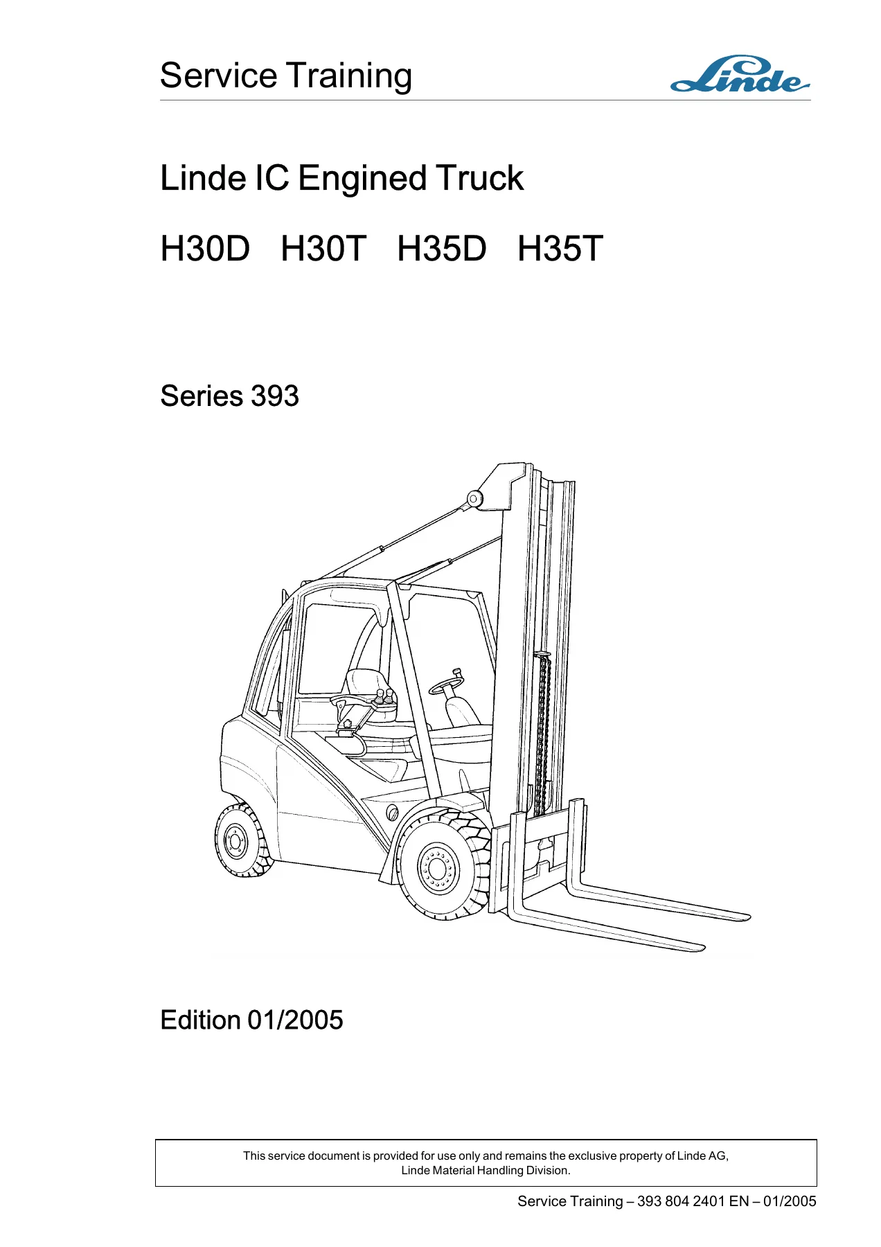
Linde H30D H30T H35D H35T Series 393 Service Training Manual 2005
Original price was: $39.95.$24.95Current price is: $24.95.
Complete Linde Series 393 service training manual for the H30D, H30T, H35D and H35T IC engine trucks – LPG VW BEF and diesel VW BEU engines, hydrostatic travel drive HPV 75-02, working hydraulics, mast and full circuit diagrams.
Description
File Details
- Manual type: Service training manual
- Brand: Linde
- Model: H30D, H30T, H35D, H35T
- Series: 393
- Document number: 393 804 2401
- Edition: 01/2005
- Language: English
- File format: PDF
Chapters Covered
- 0 Product information – the truck, diagnosis, LTC basic structure, LTC traction control codes release 1.0.0, LTC lift control codes, LTC codes of the composite instrument
- 1 Engine – LPG engine VW BEF (technical data, engine block, ribbed V-belt, toothed belt, cylinder head, compression check, hydraulic bucket tappets, cooling, engine electrical system, electronic ignition system, LPG installation, vaporiser, mixer, LPG shut-off valve, catalytic converter with Lambda control) and diesel engine BEU (electronic engine control unit, sensors, preheating system, fuel supply, injection system, injection pump, engine block, cylinder head, valve gear, cooling, engine electrical system, self-test, standardised data blocks)
- 2 Transmission – technical data about travel drive, Linde Truck Control (LTC), travel drive, hydraulic pump control with electronic control, start of delivery of the pump, bypass valve, discharge device, hydraulic fan drive, hydraulic truck diagnosis, HPV 75-02 pressure tests, hydrostatic travel drive check, wheel motor HMF 550 R sealing
- 3 Chassis – chassis and axle suspension
- 4 Undercarriage – steering system functional description, brake system, brake release valve, brake cable adjustment, brake valve, brake system check
- 6 Electrical system / electronic system – central electrical system, interface connectors console-truck, layout of relays and fuses for standard and optional equipment, composite instrument, positions of the working lights
- 7 Hydraulics – working hydraulics, functional description of the control valve, circuit diagram of working hydraulics, hose layouts for pump to control valve, control pressure supply, lifting, tilting, return flow to oil reservoir and auxiliary hydraulics for standard and duplex/triplex masts
- 8 Loading system – mast identification, mast removal and installation, installation of mast type 188, adjustment of roller clearance, removal of slide pads on standard, duplex and triplex masts, lift cylinders, tilt cylinder, tilt angle sensor adjustment, hose reel
- 9 Circuit diagrams – hydraulic circuit diagrams, wiring diagram with brake valves, electrical circuit diagrams for standard equipment, lighting options, truck data management, optional heater, soot filter and wipers
The Linde H30D H30T H35D H35T Series 393 Service Training Manual 2005 is built around numbered main sections that run from product information and diagnosis straight through to the hydraulic and electrical circuit diagrams at the back of the book. Each main section is subdivided into progressively finer subsections, so a technician can move from a system overview down to a single sensor, valve, cylinder or relay without leaving the document. Section 0 sets up the LTC architecture, the CAN bus layout and the fault code families that the composite instrument reports. Section 1 handles both engine families installed in these trucks, treating the LPG VW BEF and the 1.9-litre diesel VW BEU in parallel, including ignition, Lambda control, preheating, injection pump work and the standardised data blocks used for live diagnosis. Section 2 covers the hydrostatic side of the truck in depth, from the HPV 75-02 variable displacement pump and the HMF 550 R wheel motors to the pressure test points and the fault-finding sequence for the travel drive. Sections 7 and 8 deal with the working hydraulics, the control valve blocks and the mast assemblies, and Section 9 closes with the full set of hydraulic and electrical circuit diagrams.
What This Manual Lets You Do
The Linde H30D H30T H35D H35T Series 393 Service Training Manual 2005 is written for the person who has to open the bonnet and actually fix something. Because it covers the LPG and diesel versions of the same truck side by side, you can work on either engine variant without switching documents. Engine work is supported end to end: cylinder head removal and installation with the tightening sequence, compression values and wear limits, hydraulic bucket tappet checking, toothed belt and ribbed V-belt removal, tensioning and routing, water pump and coolant thermostat service, and coolant filling with the recommended mixing ratios.
On the diesel side, the manual walks through the Electronic Diesel Control system, the coolant temperature, engine speed, actual speed, fuel temperature, intake pipe temperature and pressure, needle stroke, height and control sleeve position sensors, the preheating system and the glow plugs, the fuel supply and metering components, the injection pump removal and installation procedure with toothed belt replacement, start of injection checking and dynamic adjustment, and the two-spring nozzle holder. Each sensor section includes a self-test note and a check procedure with resistance values, so you are not guessing at what the reading should be.
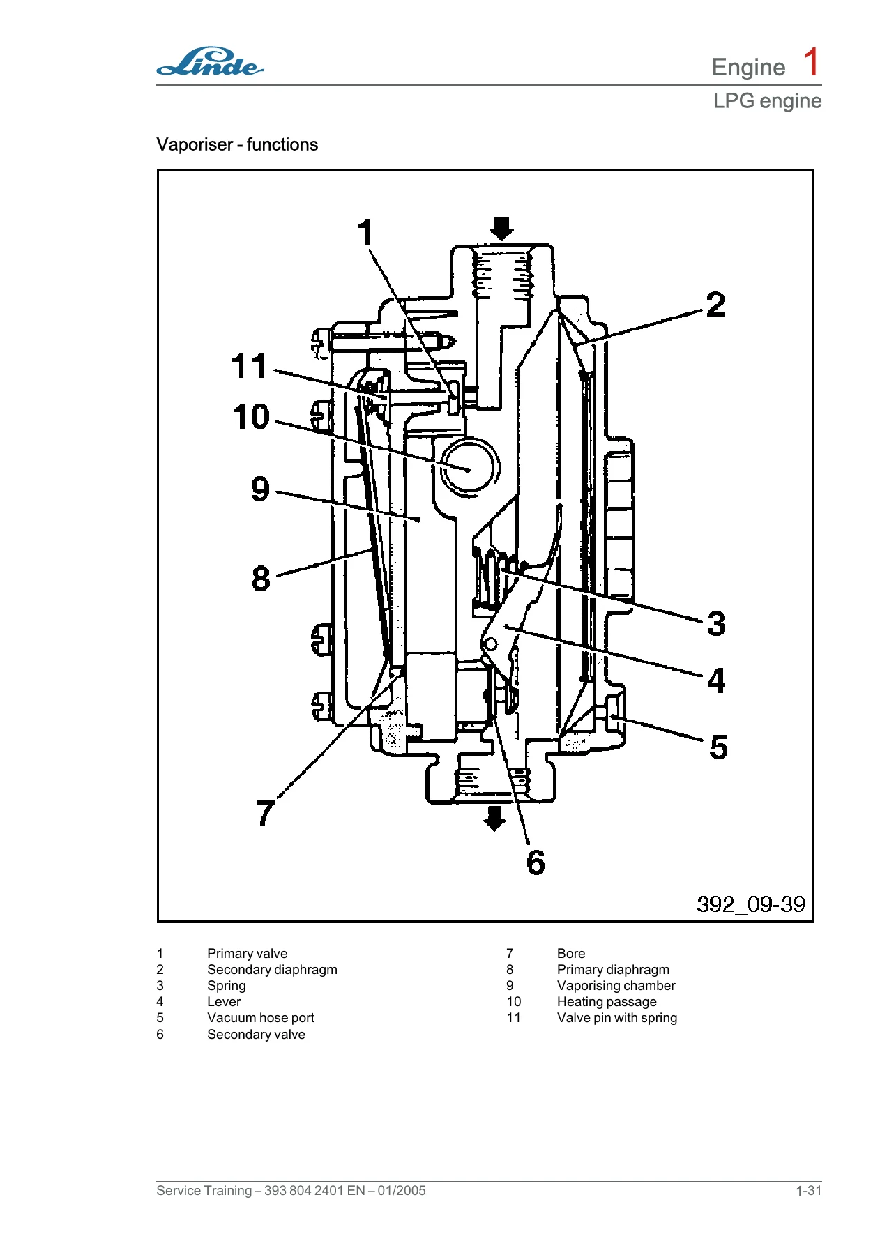
On the LPG side, the VW BEF engine documentation covers the electronic ignition system and control unit, the ignition coil checks by installation date, the throttle plate potentiometer, the phase sensor and the engine speed sensor. The LPG installation itself is covered from the vaporiser and mixer through to the shut-off valve, the catalytic converter with Lambda control, the mixer basic setting, CO content setting at idle and full load, and the calibration of the Lambda control through the service and faults windows. Wiring information for the ignition control unit is included.
Hydrostatic Drive, Hydraulics and Mast
The Linde H30D H30T H35D H35T Series 393 Service Training Manual 2005 spends a large amount of space on the hydrostatic travel drive, and that is where these trucks differ most from a conventional forklift. You get the HPV 75-02 pump control circuit, the release valve and proportional valve behaviour, the start of delivery adjustment, the swash angle adjustment and the hydraulic zero position setting, plus the pressure test point overview and the expected pressures at each test point with the accelerator and brake in different positions. The travel drive fault-finding table walks through boost pressure at the filter, the brake release valve, decoupling the AH 35-03 axle, current readings at the solenoids and the average wheel speed check, then moves on to the high pressure test with the expected 435 bar.
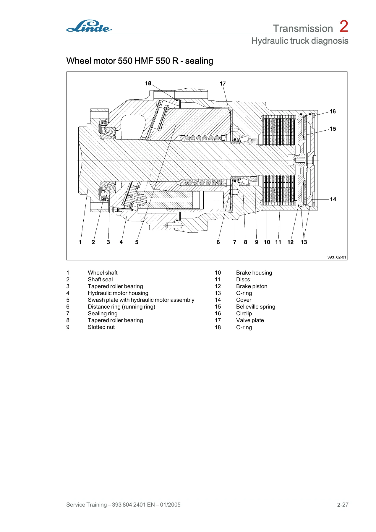
The wheel motor section covers sealing of the HMF 550 R, including the brake housing, brake discs, brake piston, slotted nut torque and the special tools needed for the job. The fan drive, bypass valve, discharge device and switch-over valve are documented with their own functional descriptions.
Working hydraulics coverage includes the LS control valve in monoblock design, the release valve, the balance valve for recirculating oil, the pressure reducing valves, the emergency lowering function, the brake valves for forward and backward tilting and the auxiliary hydraulics. Pressure settings for the control valve are given for the H30 and H35 with standard, duplex and triplex lifting scaffolds. Hose layouts are provided as separate diagrams for each circuit.
The loading system section handles mast identification, mast removal and installation, installation of mast type 188, roller clearance adjustment for the fork carrier and for outer, centre and inner masts, slide pad removal on standard, duplex and triplex masts, lift cylinder removal and sealing, tilt cylinder thread reach tables by lift height and mast type, tilt angle sensor adjustment with the reference point dimensions and the backward and forward tilt tables, and the hose reel removal, hose change, sealing and installation with the preload turns.
Diagnostics, Electrical and Circuit Diagrams
Fault code lists are included for both the traction control and the lift control at release 1.0.0, along with the composite instrument codes, so the codes shown on the display can be matched to a described condition rather than decoded by guesswork. The diesel engine self-test chapter explains how the control unit monitors sensors and actuators, how faults are graded by severity, and how the fault history is read and cleared. Standardised data blocks are laid out with the display groups, desired values and evaluation notes for each, covering engine speed, injection quantity, pump voltage, coolant temperature, exhaust gas recirculation, start of injection, fuel and intake temperatures, mass air flow and cylinder deviation.
Section 6 documents the central electrical system: the interface connectors between console and truck, the relay and fuse layout with ratings, the composite instrument indicators and their possible malfunctions, and the positions of the working lights. Section 9 then supplies the wiring diagrams themselves – standard equipment for LPG and diesel engines, the controlled catalytic converter variants, lighting options, higher lighting, truck data management, optional heater, optional soot filter and optional wipers – plus the hydraulic circuit diagrams including the version with brake valves.
Get the Manual and Start the Job
With this Linde H30D H30T H35D H35T Series 393 Service Training Manual 2005 on hand you can carry out scheduled servicing, diagnose faults reported through the LTC and composite instrument, set pressures and torques to the values the manufacturer specifies, adjust the hydrostatic travel drive, seal lift and tilt cylinders, calibrate the tilt angle sensor and rebuild the wheel motor brake. Correct procedures and correct specifications are what separate a repair that holds from one that comes back, and this document supplies both for the H30D, H30T, H35D and H35T.
IMAGES PREVIEW
Delivery is instant. The manual is a downloadable PDF that arrives as soon as payment is confirmed – no shipping, no waiting for a parcel, no customs delay. Open it on a laptop, tablet or phone in the workshop, print the pages you need for the job at hand, and keep the rest of the file as a permanent reference for the truck. Every section, table and diagram is in the same file, so the whole Series 393 documentation set stays together.
Reviews
There are no reviews yet.