
Lonking CDM856V.001 / CDM856VI.001 / CDM856NI.001 Wheel Loader Spare Parts Manual
Original price was: $24.95.$14.95Current price is: $14.95.
Complete illustrated spare parts manual for Lonking CDM856V.001, CDM856VI.001 and CDM856NI.001 wheel loaders – every system, assembly, part number, specification and quantity per unit in one bilingual Chinese/English PDF.
Description
Lonking CDM856V.001 / CDM856VI.001 / CDM856NI.001 Wheel Loader Spare Parts Manual
This is the full illustrated spare parts manual released by Lonking Holdings Limited for the CDM856V.001, CDM856VI.001 and CDM856NI.001 wheel loaders in standard configuration. Every system, assembly and individual component is documented with a bilingual Chinese/English description, the manufacturer’s part number, specification, quantity per unit and, where applicable, the original drawing reference. Instead of hunting down a single seal or hydraulic hose through dealer microfiche, you can open this manual on any device and jump straight to the exact illustration and line item you need.
The document is written for anyone who maintains, rebuilds or orders parts for these loaders – workshop technicians, fleet maintenance departments, parts counter staff and independent repair shops working on Lonking 856-series machines.
File Details
- Manual type: Spare Parts Manual (illustrated parts catalog)
- Brand: Lonking Holdings Limited
- Models covered: CDM856V.001, CDM856VI.001, CDM856NI.001
- Language: Chinese / English bilingual
- File format: PDF
- Page count: 364 pages
- Document number: 60900003040
- Publication date: October 2015
Chapters Covered
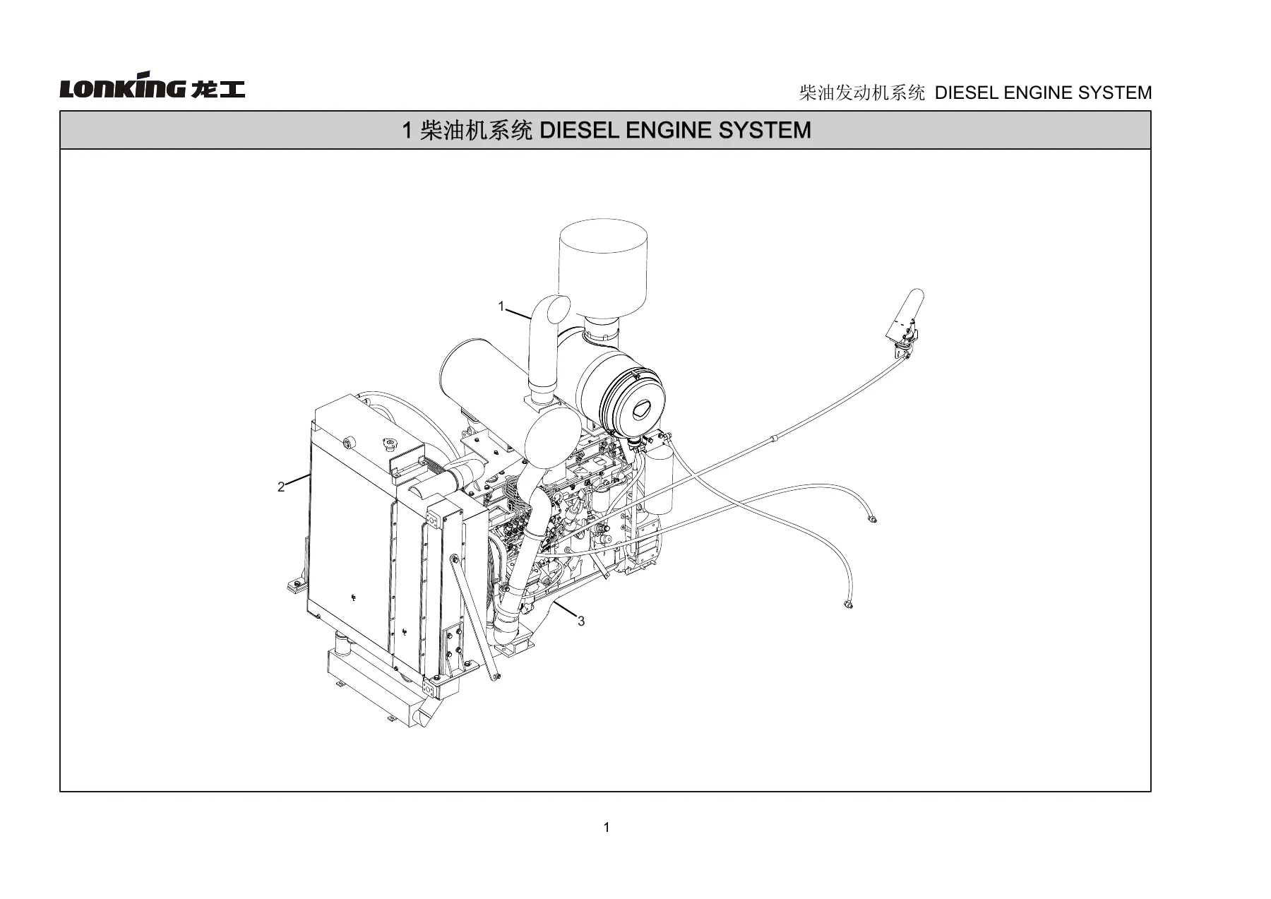
- 1. Diesel Engine System
- 1.1 Air Intake & Exhaust Parts
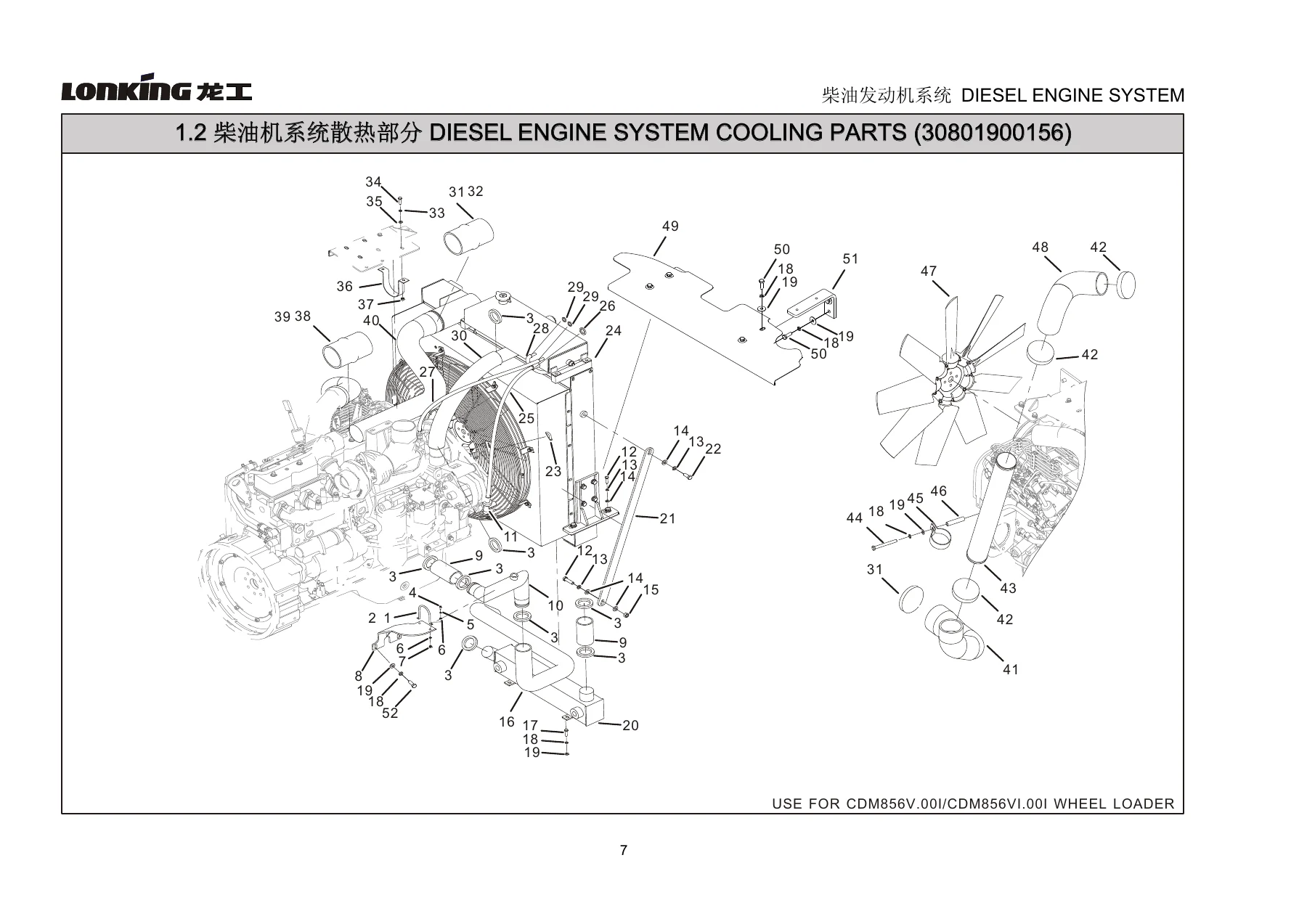
- 1.2 Cooling Parts
- 1.3 Mounts and Accessories Section Parts
- 1.3.1 Throttle Control Assembly
IMAGES PREVIEW

- 2. Torque Converter System
- 3. Transmission System
- 4. Axle System
- 4.1 Front Drive Shaft Assembly
- 4.2 Middle Support
- 4.3 Middle Drive Shaft Assembly
- 4.4 Rear Drive Shaft Assembly
- 5. Control System
- 5.1 Gearbox Control Assembly
- 5. Electrohydraulic Speed Control System
- 6. Hydraulic Steering System
- 6.1 Steering Cylinder Pipeline Installment Assembly
- 6.2 Priority Valve Pipeline Installment Assembly
- 6.3 Steering Pump Pipeline Installment Assembly
- 6.4 Steering Gear Assembly
- 7. Implement Hydraulic System
- 7.1 Working Pump Pipeline Assembly
- 7.2 Multiple Valve Pipeline Assembly
- 7.3 Boom Cylinder Pipeline Assembly
- 7.4 Bucket Cylinder Pipeline Assembly
- 7.5 Pilot Control Assembly
- 7.6 Third Pipeline Assembly
- 7.7 Boom Lift Limit Device Assembly
- 7.8 Automatic Leveling Device Assembly
- 8. Service Brake System
- 8.1 Brake Valve Pipeline Installation Assembly
- 8.2 Front Axle Pipeline Installation Assembly
- 8.3 Rear Axle Pipeline Installation Assembly
- 8.4 Relief Valve Pipeline Installation Assembly
- 8.5 Booster Pump Installation Assembly
- 8.6 Air Cylinder Pipeline Installation Assembly
- 8.7 Air Cylinder Installation Assembly
- 9. Emergency and Parking Brake System
- 10. Frame System
- 11. Implement System
- 12. Cab System
- 13. Out Panel System
- 13.1 Fuel Tank Assembly
- 13.2 Hydraulic Tank Assembly
- 13.3 Counter Weight Assembly
- 13.4 Engine Hood Assembly
- 14. Electrical System
- 14.1 Cabin Electrical Arrangement
- 14.1.1 Air Conditioner System Assembly (Evaporator, Condenser)
- 14.1.2 Front Wiper Assembly
- 14.1.3 Stand-alone IP Assembly
- 14.1.4 Central Control Box
- 14.1.5 Rear Wiper Assembly
- 14.2 Front Frame Electrical Arrangement
- 14.3 Frame Electrical Arrangement
- 14.4 Brake Valve Electrical Arrangement
- 14.5 Oil Tank Electrical Arrangement
- 14.6 Transmission Electrical Arrangement
- 14.7 Counter Weight Electrical Arrangement
- 14.8 Scrubber Electrical Arrangement
- 15. Tool Kit
- Left Steering Cylinder
- Right Steering Cylinder
- Tilt Cylinder
- Lift Cylinder
- Spare Parts Manual for Axle
- Spare Parts Manual for Transmission & Torque Converter
- Greasing Points Indication Layout
- List of Vulnerable Parts of the Engine
- Hydraulic Principle Diagram
Taken as a whole, the manual functions as a complete parts identification system for the entire CDM856 856-series loader. Each chapter opens with a numbered exploded illustration, and the accompanying table lists every callout with its part code, Chinese/English description, specification (including size, thread, grade and standard such as GB/T, AS568 or JB/T where applicable), quantity per unit and the original Lonking drawing number. Fasteners, washers, hose clamps and O-rings are all itemised right down to standard-reference level, which means you can identify the exact bolt grade or seal dimension from the drawing without guessing.
What This Manual Lets You Do
With this Lonking CDM856V.001 / CDM856VI.001 / CDM856NI.001 wheel loader spare parts manual open in front of you, ordering a replacement part stops being a phone call and a guess. You can rebuild the diesel engine intake and exhaust run, the full cooling circuit, torque converter piping, the gearbox control linkage, all four drive shaft assemblies, the middle support, the steering cylinder and priority valve pipework, the working pump and multi-valve hose runs, boom and bucket cylinder plumbing, pilot control, the service brake air circuit and booster pump, the emergency and parking brake system, the articulated frame, the boom/rocker/bucket linkage, the cab and door glass, the fuel and hydraulic tanks, the counterweight and the engine hood, plus the electrical arrangement from the cabin harness to the brake valve and transmission sensors.
Beyond the main assemblies, the appendix sections give you dedicated spare parts manuals for the cylinders (left and right steering cylinders, tilt cylinder and lift cylinder, with seal kits, guide sleeves, piston rods, joint bearings and retaining rings), for the front and rear axle assemblies (wheel-side reducers, main reducers, differentials, axle housings, bearings and seals), and for the transmission and torque converter (torque converter assembly, transmission housing, the 1st/2nd/3rd/4th shaft assemblies, pistons, friction plates and the mechanical parking brake). A greasing points layout and a list of vulnerable engine parts round out the document.
Correct part numbers are the difference between a loader that goes back to work and one that sits waiting for the wrong seal to be returned. Because every line item here carries the specification and quantity per unit, you order the right size, the right grade and the right number the first time. The PDF is delivered instantly to your account after purchase – no shipping, no waiting on a disc, readable on a phone, tablet or laptop in the workshop, and printable page by page if you prefer a paper copy next to the machine.

Reviews
There are no reviews yet.