
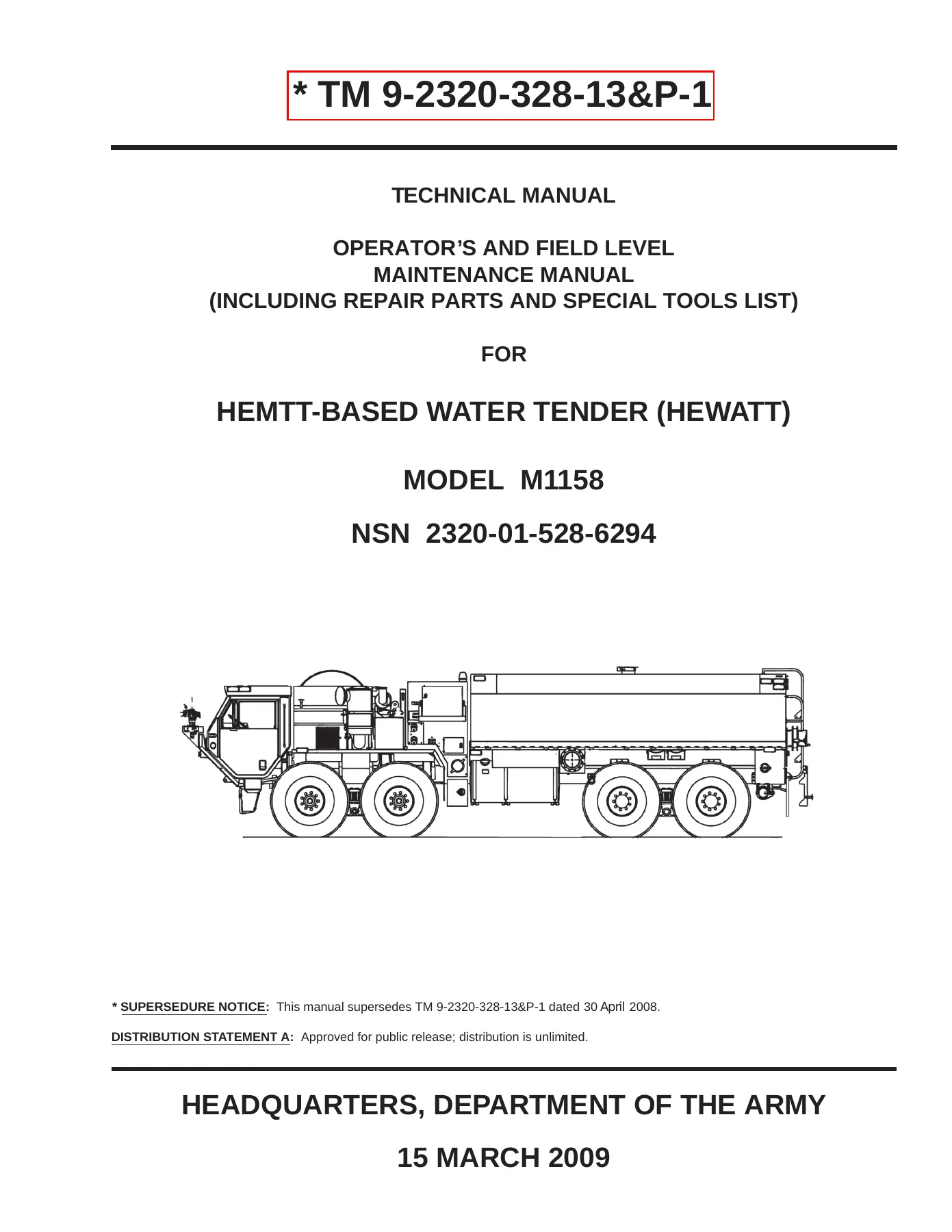
M1158 HEWATT Water Tender Operator and Troubleshooting Manual Volume 1
Original price was: $39.95.$23.95Current price is: $23.95.
Volume 1 of TM 9-2320-328-13&P-1 for the M1158 HEMTT-based water tender: equipment data, pumping, foam operation and fault diagnosis.
Description
M1158 HEWATT Water Tender Operator and Troubleshooting Manual Volume 1
This 1318-page English PDF covers the M1158 HEMTT-Based Water Tender (HEWATT) in Volume 1 of TM 9-2320-328-13&P-1. It combines equipment description and data, operator instructions and a substantial series of operator and field-level troubleshooting work packages. The title page is dated 15 March 2009; internal pages carry DRAFT markings and Change 1 references. This is Volume 1, not the complete multi-volume maintenance and parts set.
The focus is the water-tender installation and its firefighting equipment: pumping, tank filling, foam proportioning, pressure-governor controls, discharge valves, hose reel, bumper turret, under-truck nozzles, indicators and warning lights. The manual explains how these functions are distributed between the cab and pump-operator panels. It also directs the reader to the associated base-vehicle manuals where chassis information or later repair procedures are required.
File Details
- Technical manual: TM 9-2320-328-13&P-1, Volume 1.
- Equipment: M1158 HEMTT-Based Water Tender, HEWATT.
- NSN: 2320-01-528-6294.
- Title-page date: 15 March 2009.
- Edition features: internal DRAFT markings and Change 1 references.
- Language: English.
- Length: 1318 PDF pages.
- Format: PDF.
Chapters Covered
- Chapter 1 – General Information and Data: general information, equipment description and data, theory of operation.
- Chapter 2 – Operator Instructions: controls and indicators, preparation for operation and operational modes.
- Operator Instructions: battery connection, compartment doors, pump-house access, panel covers, ladders and portable water tank.
- Operator Instructions: water-tank filling and draining, water-pump priming and pressure-governor operation.
- Operator Instructions: drafting, pumping from the onboard tank, hydrant supply and relay pumping.
- Operator Instructions: foam-system information, filling, draining, flushing, standby mode and operation.
- Operator Instructions: hose reel, windshield deluge, bumper turret and under-truck nozzles.
- Operator Instructions: pump-and-roll/drive, post-operation procedures, flushing, storage and shipment preparation.
- Unusual Conditions: cold and hot environments, manual hose-reel rewind, manual priming and pumping override.
- Stowage and Data Plate Guide; On-Truck Load Plan.
- Chapter 3 – Troubleshooting Procedures: introduction, operator fault index and field-level fault index.
- Operator Troubleshooting: chargers, foam operation, governor warnings, loss of prime, leakage, lighting and abnormal discharge.
- Field-Level Troubleshooting: fire-pump system, foam proportioner, water-tank assembly and pressure-governor controls.
- Field-Level Troubleshooting: instrument-housing indicators and warning-light assemblies through work package 0112.
- Alphabetical index and metric conversion reference.
The work-package layout allows a reader to move from an observed symptom to the associated tests, inspections and corrective-action references. The operating material explains the normal behavior of the controls first, giving the diagnostic sections a clear system context.
Understand the water supply before tracing a pumping fault
The theory-of-operation chapter describes a single-stage centrifugal water pump driven hydraulically by an engine-PTO-powered hydrostatic pump. A pressure governor controls water-pump output pressure. The cab panel operates the bumper turret and under-truck nozzles, while the pump-operator panel handles side discharges and the hose reel; control interlocks support single-control operation.
Stationary pumping can use the onboard tank or an alternate supply, including a hydrant, remote pumping unit or open-reservoir draft. Pump-and-roll/drive uses the onboard water tank. The automatic direct-fill arrangement is described as maintaining tank level by opening and closing the inlet at the appropriate levels. These distinctions help identify whether a complaint concerns the source, inlet path, pump, discharge or command arrangement.
Separate operating work packages address priming, drafting through the main inlet, pumping from the onboard tank, and pumping from a hydrant or in relay. The pressure-governor material includes both cab and pump-panel displays, pressure and manual modes, preset selection, idle selection and warning or caution screens. A mode change and a supply problem are therefore treated as different operating events rather than the same generic loss of pressure.
Foam proportioning and discharge equipment
The foam system is described as an around-the-pump arrangement using an eductor between discharge and intake manifolds. Metering valves control injection for bumper-turret and under-truck-nozzle operation. The theory section identifies preset proportions of 0.5% for the bumper turret and 1.0% for the under-truck nozzles, while a manual metering valve serves side-discharge and hose-reel operation.
The manual explains that the preset arrangements depend on their intended flow conditions and that manual metering must be adjusted when flow changes. Operating work packages cover foam-agent filling, draining and flushing, standby mode, panel operation and post-use flushing. That gives the reader both the normal sequence and the context needed to understand the later foam-delivery fault charts.
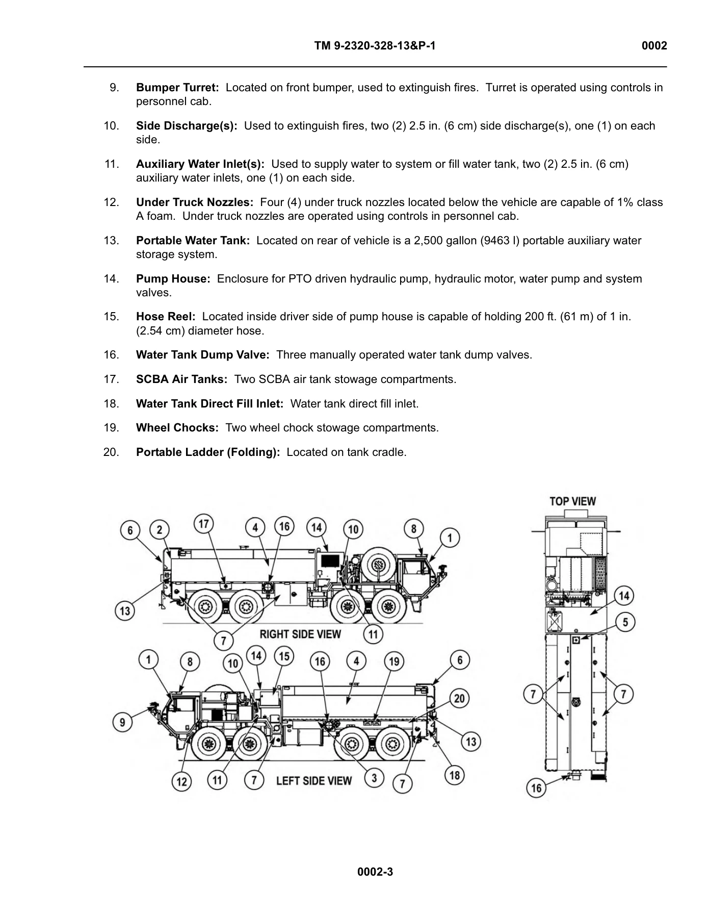
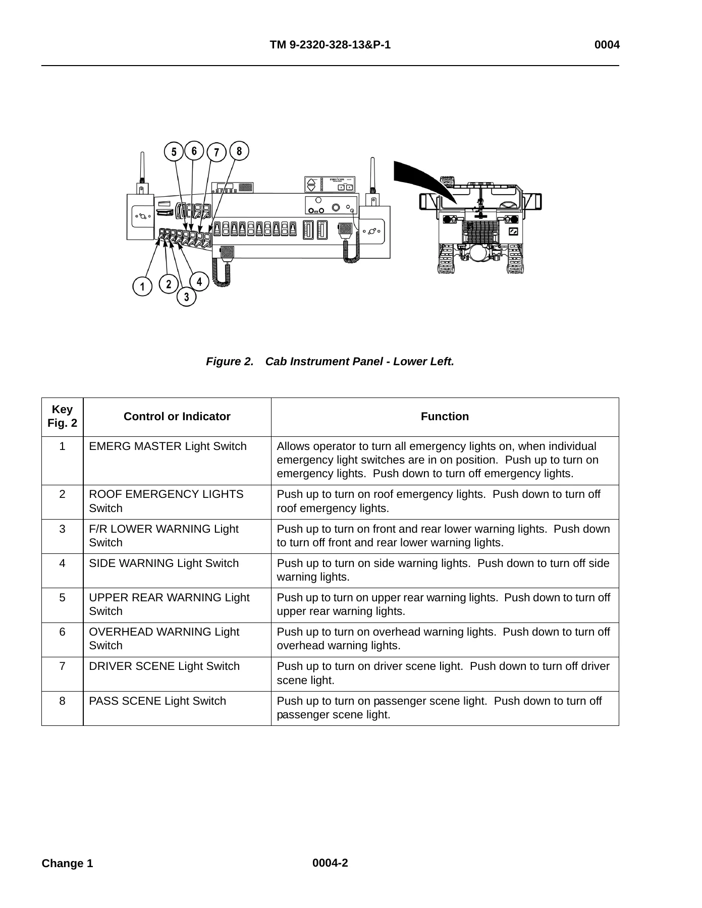
Discharge equipment has its own instructions. The hose reel, windshield deluge, bumper turret and under-truck nozzles are separately identified, along with pump-and-roll/drive procedures. Equipment descriptions locate the tank, pump house, stowage compartments, direct-fill inlet and discharge connections. The illustrated controls-and-indicators section links each switch or gauge to its function at the cab or external panel.
Fault diagnosis organized by the actual complaint
The operator fault index includes a pump that will not prime, loss of prime accompanied by LOW SUPPLY or PRESET NOT MET indications, governor warnings, leakage at drain valves or the main inlet cap, abnormal water streams and lighting or battery-charger problems. These are distinct entry points, allowing the user to begin with the observed behavior instead of guessing which component is defective.
Field-level topics go further into foam delivery from all systems or individual outlets, failure to flush, tank-level indication, direct-fill valve operation, auxiliary inlets, hose-reel rewind and discharge-valve response. Pressure-governor failure and slow response are separately indexed. Other packages address a system that will not build or hold pressure during blow-out, a noisy pump, failure of the pump PTO to engage, pump overheating and low inlet or outlet pressure.
The instrument and warning-light group treats an indicator fault separately from failure of the equipment it represents. Entries cover foam, pump cooler, tank-to-pump, tank drain, nozzle, PTO and direct-fill indications, as well as cab-switch backlighting and warning-light assemblies. Diagnostic pages use the recurring malfunction, test or inspection, and corrective-action format. Connector, wire and component illustrations accompany the relevant checks.
Preparation, shutdown and unusual conditions
The operator section begins with access and preparation tasks: batteries, compartment doors, panel covers, ladders and portable-tank stowage. It continues through water and foam operation to post-operation procedures, flushing and preparation for storage or shipment. The pump and plumbing blow-out procedure is also given its own work package, rather than being buried within a general shutdown paragraph.
Unusual-condition material addresses cold operation, extreme heat, manual hose-reel rewind, manual priming and pumping override. The equipment description states an operating-temperature capability of -25 to 120 degrees F (-32 to 49 degrees C) and describes the winterization arrangement. The instructions for these conditions remain separate from the standard operating sequence, helping the reader select the appropriate procedure.
Stowage information includes a data-plate guide and an on-truck load plan. Cab and external compartment locations are identified in the load tables, while equipment drawings show the placement of major tender components. These references support preparation and equipment identification as well as investigation of an operating complaint.
Know the boundaries of Volume 1
The opening contents also index later volumes, but the body of this PDF runs through the Volume 1 operating and troubleshooting material, ending with work package 0112 before the index and closing pages. Later maintenance and repair-parts chapters listed for other volumes are not part of this Volume 1 file. Corrective actions can refer to those later work packages or to the associated vehicle manuals.
The introductory instructions identify TM 9-2320-422-10 and the TM 9-2320-325-14&P series as companion references. The water-tender theory section likewise refers base M985 systems to the appropriate vehicle publication. Buyers seeking the complete multi-volume maintenance and parts collection should keep this scope distinction in mind; this file provides the substantial operating and troubleshooting volume.
Equipment data tied to named components
The equipment table separates the 2,500-gallon onboard water tank from the 2,500-gallon portable tank and the 50-gallon foam tank. Pump-hydraulic reservoir, hydraulic-pump gear-case, priming-tank and water-pump gear-case quantities each have their own entries. Keeping those names attached to their quantities prevents a capacity from being confused with a different part of the water-tender installation.
The Darley HH500 water pump is identified as a single-stage centrifugal unit with a hydraulic PTO-powered drive package and mechanical seals. Its rated flow is stated together with pressure, while the bumper turret, side discharges, hose reel and under-truck nozzles have separate discharge entries. The table also gives net pump pressure at full rated capacity and at two reduced-capacity points. These are reference operating points, not interchangeable pressure settings for every outlet.
Vehicle information includes overall dimensions, reduced shipping height, wheelbase, wall-to-wall turning circle, ground-clearance exceptions, curb weight and gross vehicle weight rating. The controls and component descriptions add the physical arrangement: the pump house, tanks, hose reel, portable-tank stowage and cab or external control locations. Read together, these sections describe both the tender installation and the operating environment in which its water and foam systems are used.
Keep the HEWATT operating reference accessible
The M1158 HEWATT Water Tender Operator and Troubleshooting Manual Volume 1 supports equipment familiarization, selection of operating procedures and systematic investigation of pumping, foam, control and lighting complaints. Its work-package structure, equipment data and illustrated checks help preserve the correct sequence and reference context. Receive the PDF instantly after payment, without shipping, and consult it on a compatible device or print the operating and diagnostic pages needed for reference.
Reviews
There are no reviews yet.