
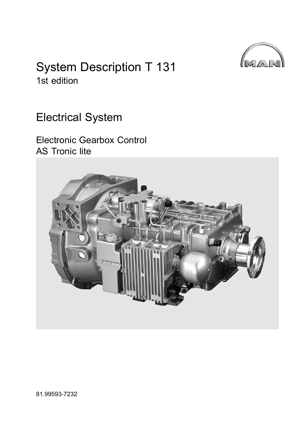
MAN AS Tronic lite Electronic Gearbox Control System Description T 131 – TGL Workshop Manual PDF
Original price was: $43.95.$28.95Current price is: $28.95.
MAN Nutzfahrzeuge AG system description T 131 for the AS Tronic lite electronic gearbox control (EMOS) fitted to the MAN TGL 7.5, TGL 8 and TGL 12. Covers the powerpack, gearbox and clutch actuators, CAN structure, function diagrams, component pinouts and the full SPN fault code list. English, 1st edition, 146-page PDF.
Description
MAN AS Tronic lite Electronic Gearbox Control — System Description T 131
This is the complete English-language system description for the MAN AS Tronic lite electronic gearbox control (EMOS) — the automated manual transmission with an electro-hydraulically shifted synchromesh gearbox and an automated dry clutch, fitted to the light-duty MAN TGL range. Issued by MAN Nutzfahrzeuge AG as document T 131, first edition, copy deadline 12.2009, it explains how the system is built, how it shifts, how each component is wired and pinned out, and how every fault it can report is diagnosed.
File Details
- Manual type: Electrical system — electronic gearbox control system description
- Manufacturer: MAN Nutzfahrzeuge AG, Munich
- Document number: T 131
- Edition: 1st edition, copy deadline 12.2009
- Language: English (English edition of the German Systembeschreibung)
- File format: PDF
- Pages: 146
- Wiring diagram sheets: AS Tronic lite overview sheets, with and without multifunctional steering wheel, and with PTO I and PTO II
Chapters Covered
- Introduction — safety instructions, overview of models, explanatory notes to the wiring diagrams
- Device description — system description, AS Tronic lite design, AS Tronic lite functions, components, CAN databus and system structure
- Functional description — AS Tronic lite gearbox components, Tipmatic lite gearbox system components, function diagram, diagnosis with MAN-cats II
- Component description — control unit, gearbox actuator, clutch actuator, tachograph pulse generator, power take-off, mode switch, steering column stalks
- Diagnosis — general information and the AS Tronic lite SPN fault code list
- Additional wiring diagrams
Introduction
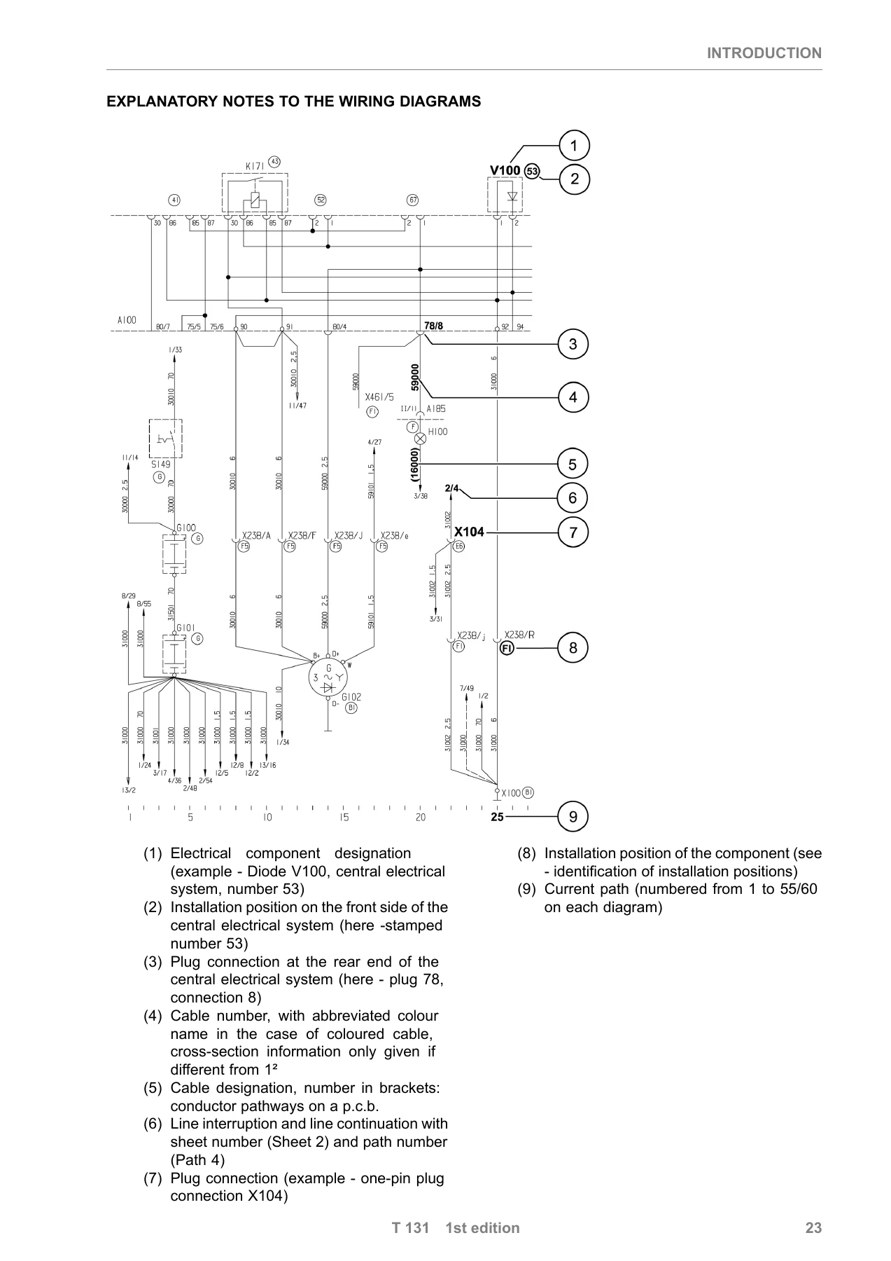
Opens with the safety instructions that govern work on the vehicle electrical system, the brake system, high-pressure lines and the compressed natural gas system, followed by the model overview table that lists exactly which trucks the AS Tronic lite system description applies to. The wiring-diagram key then explains how component designations, installation positions, plug connections, cable numbers, conductor pathways and sheet/path cross-references are read on every diagram in the book.
Device Description
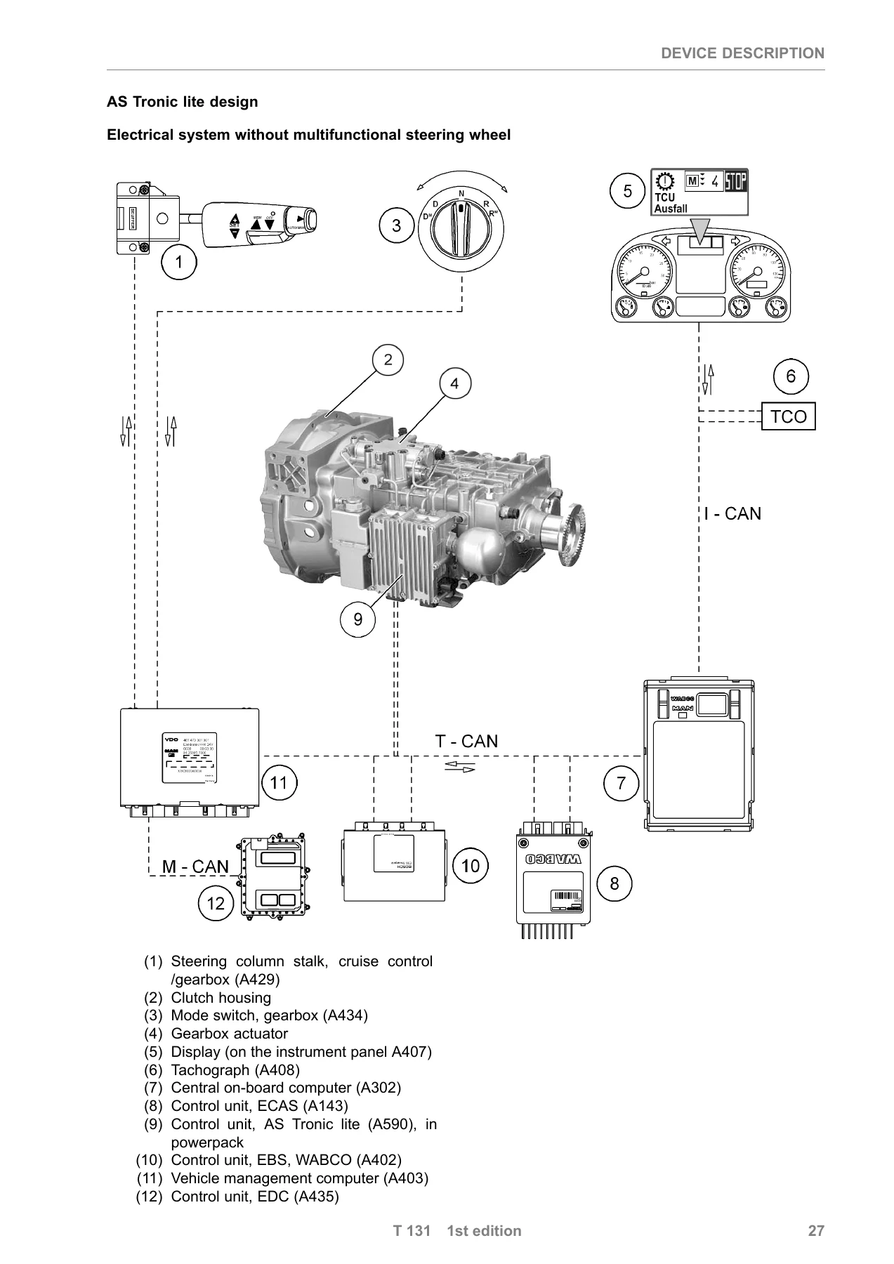
Explains why automated gearboxes moved into the light commercial vehicle segment and how the AS Tronic lite system is assembled. The AS Tronic lite design is shown twice — with and without a multifunctional steering wheel — alongside the hydraulic system layout. The CAN databus and system structure section maps how the gearbox control unit (A590), the vehicle management computer (A403), EBS, ECAS, EDC, instrumentation and the tachograph are networked across T-CAN, I-CAN, M-CAN, H-CAN and A-CAN.
Functional Description
Covers the shift mechanism, engine overspeed protection, starting off, manoeuvring (RM/DM), the starter interlock and the clutch control strategy, including how the clutch is slipped and the engine torque influenced through the EDC interface. The upshift and downshift function diagrams trace, over a common time axis, the gearbox input speed, engine speed, clutch state, gear engaged/disengaged, synchronisation and select signal, so the complete sequence can be followed step by step. The Tipmatic lite gearbox system components — powerpack, gearbox actuator, clutch actuator and the ZF gearbox wiring harness — are described together with their connector pin assignments.
Component Description
Each major component gets its own section with a design photograph, its installation position on the vehicle and, where relevant, its pinout and technical data. Covered components include the AS Tronic lite control unit (A590) with its 21-pin vehicle connector X1, 15-pin gearbox add-on connector X3 and 2-pin high-current connector X29; the gearbox actuator with its blocking pieces, selector finger, shift and select position sensors; the clutch actuator with its integrated PLCD position sensor; the tachograph pulse generator (B110), also known as the KITAS sensor; the power take-off; the mode switch (A434) with its D, DM, N, R and RM positions; the cruise control/gearbox steering column stalk (A429); and the retarder/gearbox steering column stalk (A942).
Diagnosis
The diagnosis chapter sets out how faults are detected, prioritised, displayed and stored. It documents the full SPN fault code list for the AS Tronic lite, giving each code its plain-text description, FMI status indicator, priority, fault display behaviour, effect of fault, cause and remedy. Codes run from SPN 00070 (parking brake defective signal) through to SPN 04186 (vehicle speed signals), covering speed and torque signals, accelerator and brake signals, CAN timeouts and busoff faults, the clutch and gearbox controllers, the main shut-off relays, the hydraulic valves, the pressure and temperature sensors, and the internal powerpack checks. The diagnostic priorities, the behaviour of the central warning light (H111) and the gearbox check lamp (H179), the display layout on both Baseline and Highline Stoneridge instrumentation, and the MAN-cats II menu tree are all described. Troubleshooting guidance for resistance and voltage measurement is included, with the T-CAN expected at 60 ohms.
Additional Wiring Diagrams
The closing section provides the AS Tronic lite wiring diagrams as overview sheets — without multifunctional steering wheel, with multifunctional steering wheel, and with PTO I and PTO II — showing the control unit, fuses, plug connections and the CAN lines running out to the rest of the vehicle.
Hydraulic and Electrical Detail You Can Work From
The system description does not stop at block diagrams. It gives you the numbers you need to test and repair the AS Tronic lite with confidence. The diaphragm reservoir runs at a system pressure of between 60 and 80 bar; the electric motor driving the gear pump is deactivated at 80 bar and reactivated at 60 bar. The reservoir takes Pentosin hydraulic fluid CHF 11S and carries an integrated fill level sensor. The powerpack carries the control unit, the hydraulic block with its solenoid valves, the excess pressure valve, the non-return valve, the pressure sensor, the pump motor and the diaphragm reservoir, and it connects to the gearbox actuator through four hydraulic lines.
The gearbox actuator itself has four hydraulic connections and two contactless position sensors that measure the select and shift cylinders on the plunger coil principle. The clutch actuator is an externally mounted positioning cylinder with an internal master-slave piston system, so the maximum clutch release travel stays constant regardless of clutch wear — cup spring damage is prevented even if a fault occurs. Its release travel is measured by a permanent-magnetic linear contactless displacement sensor.
Who This MAN AS Tronic lite Manual Is For
This is the document a workshop reaches for when an AS Tronic lite equipped TGL will not select a gear, when a clutch fault code appears on the display, when the gearbox check lamp comes on, or when a CAN timeout has to be tracked down between the gearbox control unit and the vehicle management computer. Because the T 131 system description ties the electrical, hydraulic and diagnostic sides of the gearbox together in one document, it supports component-level diagnosis rather than parts swapping — you can read the valve control signals, the sensor positions, the switch logic of the mode switch and steering column stalk, and the SPN fault text before you touch the vehicle.
The SPN fault code list is the strongest part of the book for everyday repair work. Each entry gives the priority the fault carries, whether the display shows a yellow warning or a red STOP, what the control unit does when the fault is active, what causes it, and which test steps to work through. That structure applies right across the list, from signal-level faults such as the accelerator pedal angle or the gearbox input speed, through the clutch and shift controllers, to the internal main shut-off relays and the hydraulic valve diagnostics inside the powerpack.
IMAGES PREVIEW
Instant PDF Delivery
The MAN AS Tronic lite Electronic Gearbox Control System Description T 131 is delivered as a PDF download immediately after checkout — no shipping, no waiting, no physical binder. Read it on a laptop or tablet in the workshop, print the pages you need for the job in hand, or keep it on a phone for a quick look at a pinout or a fault code. Whether you are servicing a TGL 7.5, an 8-tonner or a TGL 12, this 146-page English edition gives you the manufacturer’s own system description for the AS Tronic lite gearbox control, with the wiring diagrams, function traces, component pinouts and fault code list in one file.
Reviews
There are no reviews yet.