

Mitsubishi Fuso FP FV FS Body Equipment Mounting Directives 2013 Australia/New Zealand Technical Manual PDF
Original price was: $34.95.$19.95Current price is: $19.95.
Body/equipment mounting directives for Mitsubishi Fuso FP, FV and FS trucks in Australia/New Zealand. Covers technical sections, chassis modifications, body construction, electrics, brake systems, fuel tank and battery mounting, and more.
Description
This Mitsubishi Fuso FP FV FS Body Equipment Mounting Directives 2013 Australia/New Zealand PDF is the technical reference for body builders, converters and workshops working on Fuso FP, FV and FS truck chassis. Issued by Mitsubishi Fuso Truck & Bus Corporation, the document gives the dimensional, structural, electrical and safety information needed to plan and mount bodies, equipment and auxiliary components without compromising the vehicle. It is arranged in ten linked chapters, with detailed technical data for the Australia/New Zealand market.
File Details
- Manual type: Body/equipment mounting directives
- Brand: Mitsubishi Fuso
- Model series: FP, FV, FS
- Covered engines: OM457, 6M70T3, 6M70T4
- Market: Australia/New Zealand
- Language: English
- Page count: 155 pages
- File format: PDF
- Edition/revision: Revised Jan 2013
- Document number: BH1201
Chapters Covered
- 1 Introduction
- 2 General
- 3 Planning of bodies
- 4 Technical threshold values for planning
- 5 Damage prevention
- 6 Modifications to the basic vehicle
- 7 Construction of bodies
- 8 Electrics/electronics
- 9 Calculations
- 10 Technical data
- 10.1 Model line-up
- 10.2 Specifications
- 10.3 Performance curve
- 10.4 Weight distribution table
- 10.5 Chassis cab drawings
- 10.6 Frame structure
- 10.7 Spring characteristics
- 10.8 Propeller shaft layout
- 10.9 Power take-offs
- 10.10 Exhaust system layout
- 10.11 Battery mounting layout
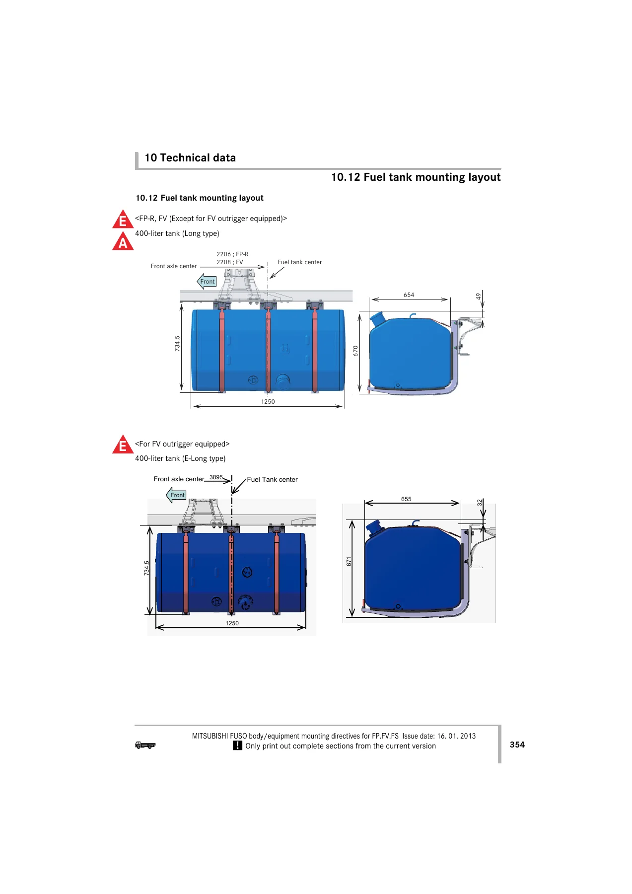
- 10.12 Fuel tank mounting layout
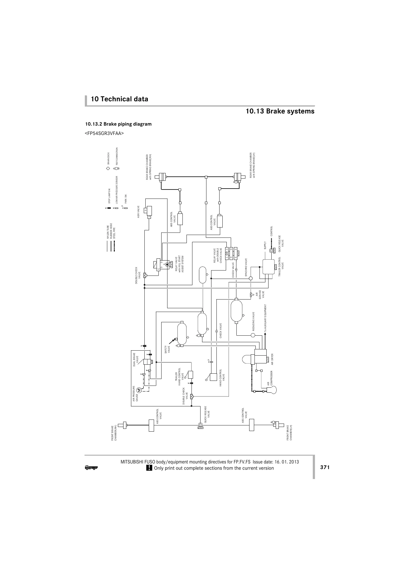
- 10.13 Brake systems
- 10.14 Electrical systems
- 10.15 Other equipment
Across these chapters, the Mitsubishi Fuso FP FV FS Body Equipment Mounting Directives 2013 Australia/New Zealand manual explains how to select the chassis, assess weight distribution and centre of gravity, allow for steerability and clearance, and protect brake hoses, wiring, fuel lines and chassis components during body installation. It also covers modifications to the basic vehicle, including chassis frame drilling and welding, reinforcements, wheelbase changes, power take-offs, propeller shafts, brake systems, exhaust and fuel systems. The body construction section deals with mounting frames, attachment methods and general body-building practice, while the electrical chapters explain wiring, power supply, charging balance, electric welding precautions, lighting and mobile communications systems. The technical data chapter provides model specifications, performance curves, chassis cab drawings, frame structure details, spring characteristics, battery and fuel tank mounting layouts, brake system information and electrical system data. This makes the PDF a practical reference for planning, fabricating and installing bodies and equipment on Fuso FP, FV and FS trucks.
What This Manual Helps You Do
With the Mitsubishi Fuso FP FV FS Body Equipment Mounting Directives 2013 Australia/New Zealand PDF, body builders and technicians can work from the manufacturer’s mounting requirements rather than guesswork. It supports tasks such as checking permissible overhang and wheelbase, calculating axle loads, verifying body incline limits, positioning mounting frames, avoiding damaging welding or drilling practices, and routing electrical and air systems correctly. The brake system chapters help with air tank layout and braking performance calculation, while the fuel tank and battery mounting sections give dimensions and mounting positions. The electrical system diagrams and fuse box layouts help diagnose and add circuits safely, including PTO, lighting, trailer and communication equipment. For workshops that convert or repair Fuso FP, FV and FS trucks, this body equipment mounting manual provides the technical thresholds and installation details needed to keep the vehicle safe, stable and within specification.
Why Correct Mounting Information Matters
Body and equipment mounting affects vehicle stability, load distribution, braking, handling and electrical reliability. Using incorrect dimensions, unsupported chassis modifications or improper welding and drilling can create safety hazards, premature component failure or compliance problems. This Mitsubishi Fuso body mounting directives PDF gives the correct procedures, clearances, weight limits, torque references and system layouts for FP, FV and FS models, so body builders can avoid damage to the chassis, brake system, fuel system and electrical network. It is especially useful when installing cranes, tippers, mixer bodies, semi-trailer equipment, outrigger-equipped bodies or other special-purpose equipment where mounting points and reinforcement details matter.
IMAGES PREVIEW
Instant PDF Delivery
The Mitsubishi Fuso FP FV FS Body Equipment Mounting Directives 2013 Australia/New Zealand technical manual is delivered as an instant PDF download after payment. There is no shipping and no waiting for a physical book. You can open it on a computer, tablet or smartphone, print the pages you need for the workshop, and keep the file on hand for future body-building or repair projects. Whether you are a professional body manufacturer, fleet workshop or independent technician, this PDF gives you immediate access to the mounting directives for Fuso FP, FV and FS trucks.
Get the Mitsubishi Fuso FP FV FS Body Equipment Mounting Directives 2013 Australia/New Zealand PDF today and work with the correct chassis, body, electrical and brake system information for these Fuso truck models. Instant download, printable, and ready for your next body or equipment installation job.



Reviews
There are no reviews yet.