
Isuzu C-Series E-Series 2010 Body Builders Guide PDF – Australia NZ South Africa Truck Manual
Original price was: $39.95.$23.95Current price is: $23.95.
Official Isuzu Body Builders Guide for C-Series and E-Series cab chassis and tractor models sold in Australia, New Zealand and South Africa. Covers rear body mounting, chassis modification, weight distribution, PTO, electrical systems, spring data and full chassis frame drawings.
Description
File Details
- Manual type: Body Builders Guide (rear body mounting and chassis modification reference)
- Brand: Isuzu
- Model lines covered: C-Series and E-Series cab chassis and semi tractor
- Markets: Australia, New Zealand, South Africa
- Language: English
- Format: PDF
- Pages: 529
- Edition/date: February 2010, with an additional C-Series for Australia version dated October 2011 (document reference FR0-BBG-2011-0041)
- Issued by: Isuzu Motors Japan Limited / Isuzu Australia Limited
Chapters Covered
- 1-1 Introduction
- 1-2 Identifying a Cab Chassis — ID plate, certifications, ID code components, VIN, location of ID numbers, vehicle model code chart
- 2-1 Principal Specifications of the Cab Chassis for Australia
- 2-2 Principal Specifications of the Cab Chassis for New Zealand
- 2-3 Principal Specifications of the Cab Chassis for South Africa
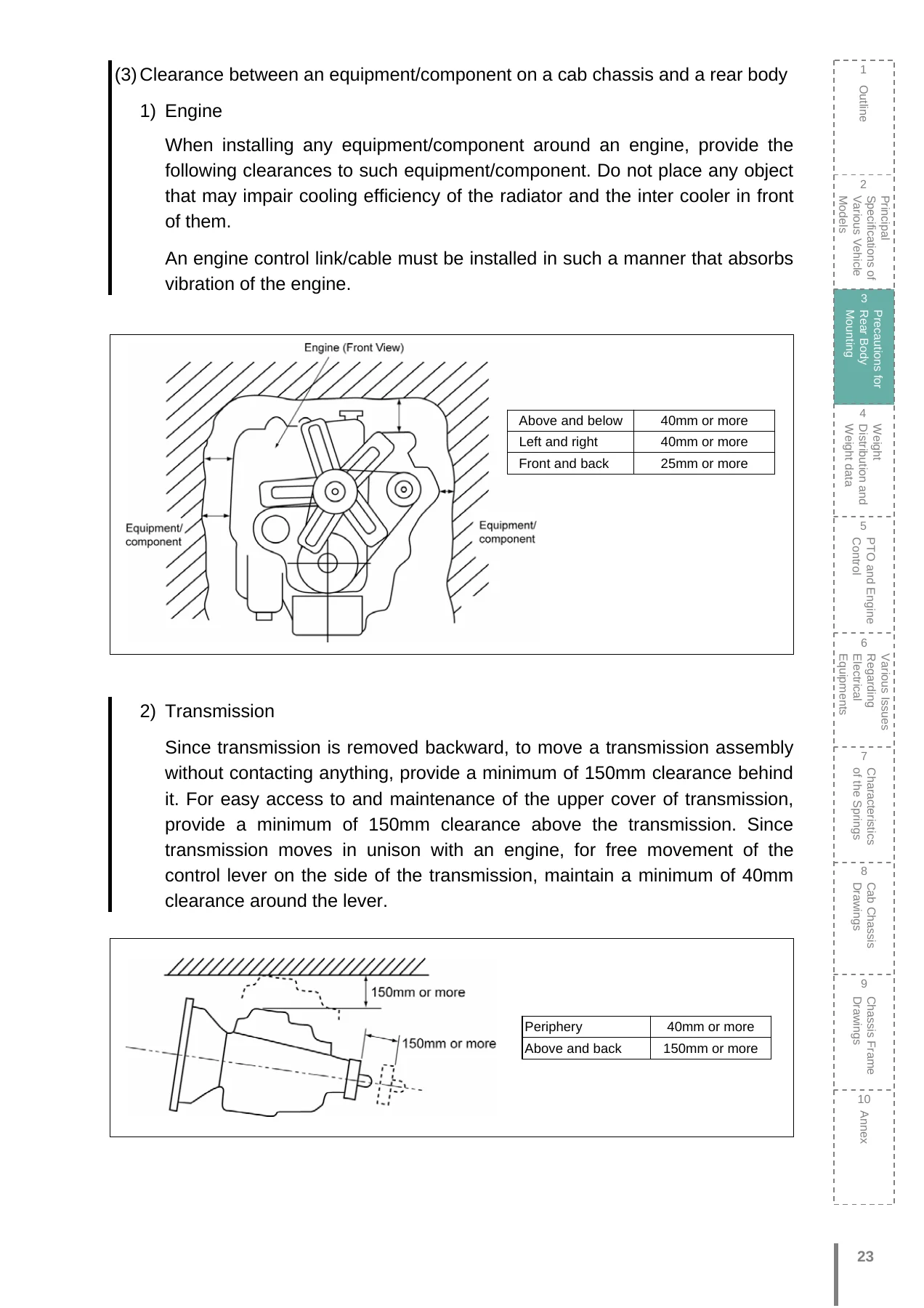
- 3-1 General Precautions — prohibited modification, maintainability, clearance to engine, transmission, propeller shafts, exhaust system, brake hoses and suspension, SRS airbag, DPD, rear view mirror and rear body width, air suspension chassis, painting disc wheels
- 3-2 Precautions for Mounting of a Rear Body — fixing bolts, sub frame design and fitting, areas free of fixing bolts, U-bolt and double-ended bracket fitting, fenders and rubber mud guards
- 3-3 Precautions for Modification of a Chassis Frame — load on side member, drilling or welding, reinforcing, modifying rear overhang, rivet plate
- 3-4 Precautions for Modification of Chassis Components — exhaust system, fueling system, AMT installation, V-rod projection
- 3-5 General Precautions for Brake-Related Components — ABS and EBS, LSPV, brake and clutch pipe, hydraulic and air steel pipes, nylon air tube and push-in connector, APU air inlet/outlet and brake chamber paint-free areas, air extraction, retarder
- 3-6 Precautions for Cab Modification — modification or addition to a cab, equipment on a roof, roof load limits, through holes for harnesses or antenna cable, cab roof panel work
- 3-7 Precautions for Cab Painting — top coat, paint boundaries, paint drying, removing control units with built-in computers, laminated glass, emblems and decals, rust prevention
- 4 Weight Distribution and Weight Data — weight distribution, weight data, weight distribution calculation, allowable front axle load, allowable load on axles and tires
- 5 PTO and Engine Control — PTO variation, transmission side PTO (medium and high capacity), PTO control, governor characteristics curves
- 6 Electrical Equipments — AC generator working voltage and output, precautions for electrical modification, electric wiring, fuses, relays, adding power sources, adjusting lamp positions, circuit diagram symbols, circuit diagrams
- 7 Characteristics of the Springs — spring specifications, formula for calculating chassis frame top surface ground height, margin for axle and tire movement, maximum projection of sliding-type rear axle spring
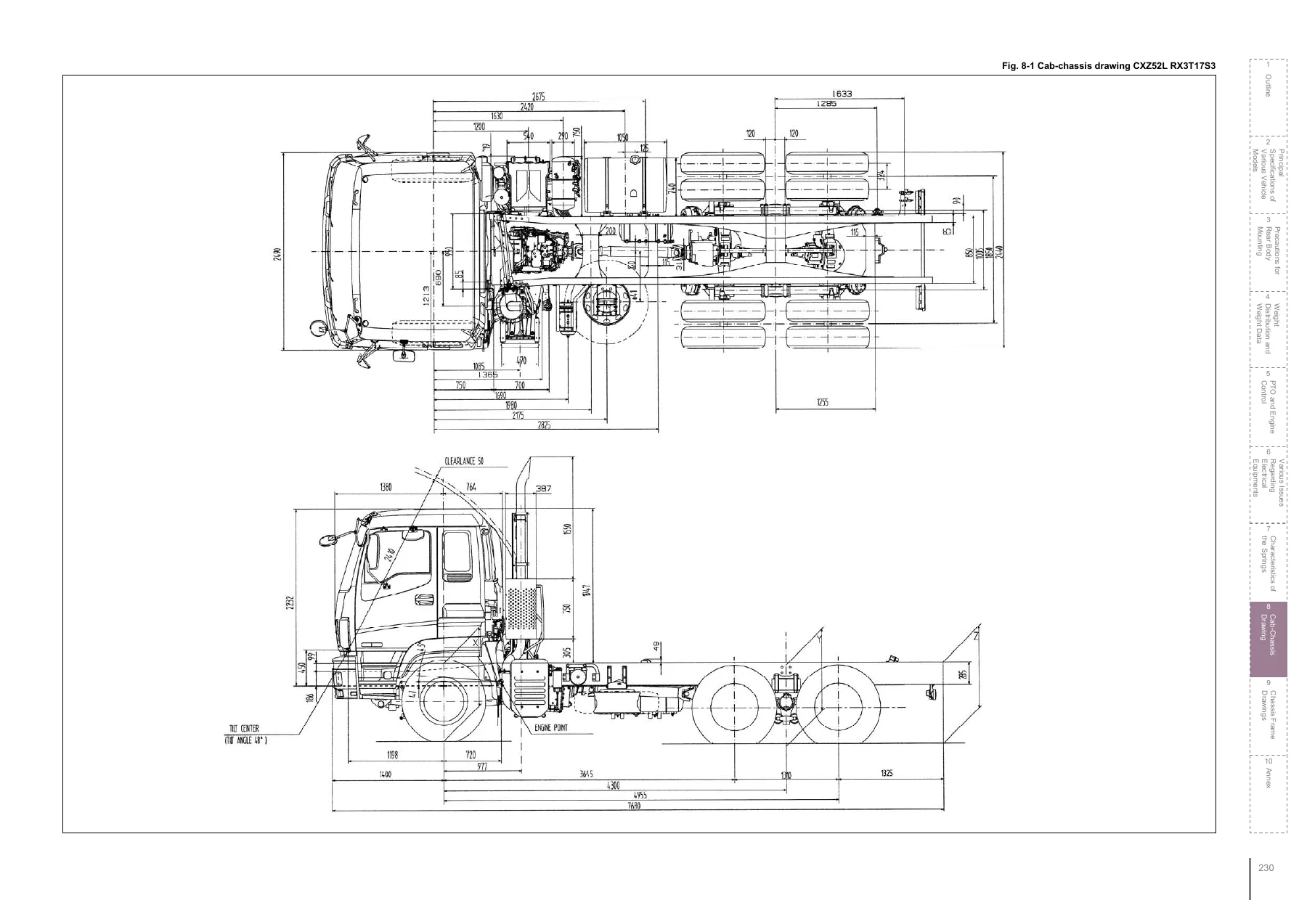
- 8 Cab Chassis Drawings
- 9 Chassis Frame Drawings — including detailed cross member drawings
- 10 Annex — piping diagrams, location of fuel tank, battery, air tank complex, APU and purge tank, spare tire and carrier, exhaust silencer and tail pipe
This Body Builders Guide is the reference document Isuzu supplies to the body builders who complete the final stage of vehicle manufacture by mounting rear bodies on Isuzu cab chassis. It is written for the workshop that has to make the rear body, sub frame, wiring, piping and PTO systems fit and function correctly on a C-Series or E-Series chassis sold in Australia, New Zealand or South Africa. Every clearance figure, torque requirement, prohibited modification area, sub frame end shape, U-bolt spacing rule and weight distribution formula in the guide is presented so the completed vehicle keeps its ADR compliance, safety, durability and warranty intact.
What You Can Do With This Guide
The value of this manual is that it tells you what Isuzu permits and what it forbids — and it gives the actual numbers behind each rule. Instead of guessing whether a hole can be drilled in a chassis frame flange, how far a sub frame end should sit behind the cab mount, how much clearance an exhaust silencer needs from a wooden body, or where a body builder is allowed to tap into the factory air supply, the guide states the limit and shows the geometry.
You can use it to design a sub frame that follows the correct front end shapes for flat bed, aluminum van or special equipment bodies, to position the first fixing bolts correctly relative to the kick-up point, and to space the remaining bolts within Isuzu’s limits. You can use it to check that any proposed chassis frame modification — a hole, a reinforcement, a rivet plate or a rear overhang extension — falls inside the permitted maximum hole diameter, work-prohibited zone and minimum distance rules for heavy, medium and light duty frames.
The guide also walks through the modifications that are simply not allowed: cutting the chassis frame, welding on flanges, relocating or modifying the exhaust front pipe and silencer (including the DPD on Australian models), altering brake or clutch pipes, changing air suspension control harnesses, modifying ABS or EBS wiring, and painting the air inlet or outlet of APU and brake chambers. If a modification has to happen, the guide explains how to do it correctly — which welding rod to use on HT540 or JSH440 frame steel, how to ground the welder, which components to disconnect first, and what to re-apply afterwards.
Weight Distribution, PTO and Electrical Content
One of the most practical parts of the manual is the weight distribution chapter. It provides the basic formulas for working out how a completed C-Series or E-Series vehicle will sit on its front and rear axles once the rear body and cargo are added, including the equations used for CXZ, CXY, CYZ, CYJ, CYH, EXD, EXY and EXZ layouts, the unsprung load values for each axle configuration, and the accepted front axle load percentage range. The weight data tables list cab chassis weight by model so you can run the calculation before committing to a body build.
PTO and engine control is covered in detail. The guide lists which transmission models accept a medium-capacity or high-capacity transmission side PTO, gives the output torque, gear ratio, output shaft rotating direction, mounting dimensions, flange drawings and gear tooth data for the MJX12P and MJX16P units, and explains external engine control — the switching conditions between running governor characteristic and rear body operation governor characteristic, the PTO switch circuits, and how to add a surge-absorbing diode when fitting a non-Isuzu magnetic valve.
The electrical chapter covers AC generator working voltage and output by model, fuses (blade and slow-blow, with their ratings and the equipment each one protects), relays and where they sit inside the cab, how to add power sources for marker lamps, stop lamps, back-up lamps and general service power, and how to connect a large-load equipment directly to the positive battery terminal with the correct fuse placement and grounding practice.
Drawings and Diagrams Included
The guide closes with the cab chassis drawings, chassis frame drawings, detailed cross member drawings and piping diagrams. These are the layout references you need when positioning a body, routing new pipework, checking the frame section modulus along the wheelbase, or confirming where the factory air tanks, fuel tank, battery, APU, spare tire carrier, exhaust silencer and tail pipe are located on each model. Component location drawings are provided per model and per market so the numbers match the truck in front of you.
Why This Matters for a Completed Vehicle
Rear body mounting and chassis modification on a heavy truck is not a job where a close-enough figure works. A sub frame end that is shaped wrongly, a fixing bolt placed inside a prohibited zone, a heat source left too close to a resin or rubber component, or a wiring splice made in the wrong place can lead to cracked chassis frame members, heat damage, brake or fuel system failure, or a vehicle that no longer complies with its ADR approval. The Isuzu Body Builders Guide is written to stop those failures happening before the body is fitted, with clear numerical limits instead of general advice.
Because the guide also covers the country-specific requirements — Australian Design Rules for rear lamps, wheel guards and rear registration plate provision; equivalent New Zealand and South African standards; and the DPD system fitted to Australian models — it is directly usable for a vehicle being completed in any of the three markets. Body builders, fleet engineers and workshop supervisors who need to sign off on a C-Series or E-Series rear body installation get the correct procedure and the correct figure in one document.
Delivery
IMAGES PREVIEW
The Isuzu C-Series and E-Series Body Builders Guide is supplied as an instant-download PDF. There is no shipping, no waiting for a physical binder, and no regional restriction. The file opens on any laptop, tablet or phone, can be printed for the workshop floor, and can be kept on a shared drive so the whole fitting team works from the same reference. Buy once and use it on every cab chassis job where a body is going onto an Isuzu C-Series or E-Series truck.


Reviews
There are no reviews yet.