
Iveco S-Way MY2023 Diesel Electrical Schematics Manual – Complete Wiring Diagrams PDF
Original price was: $52.95.$34.95Current price is: $34.95.
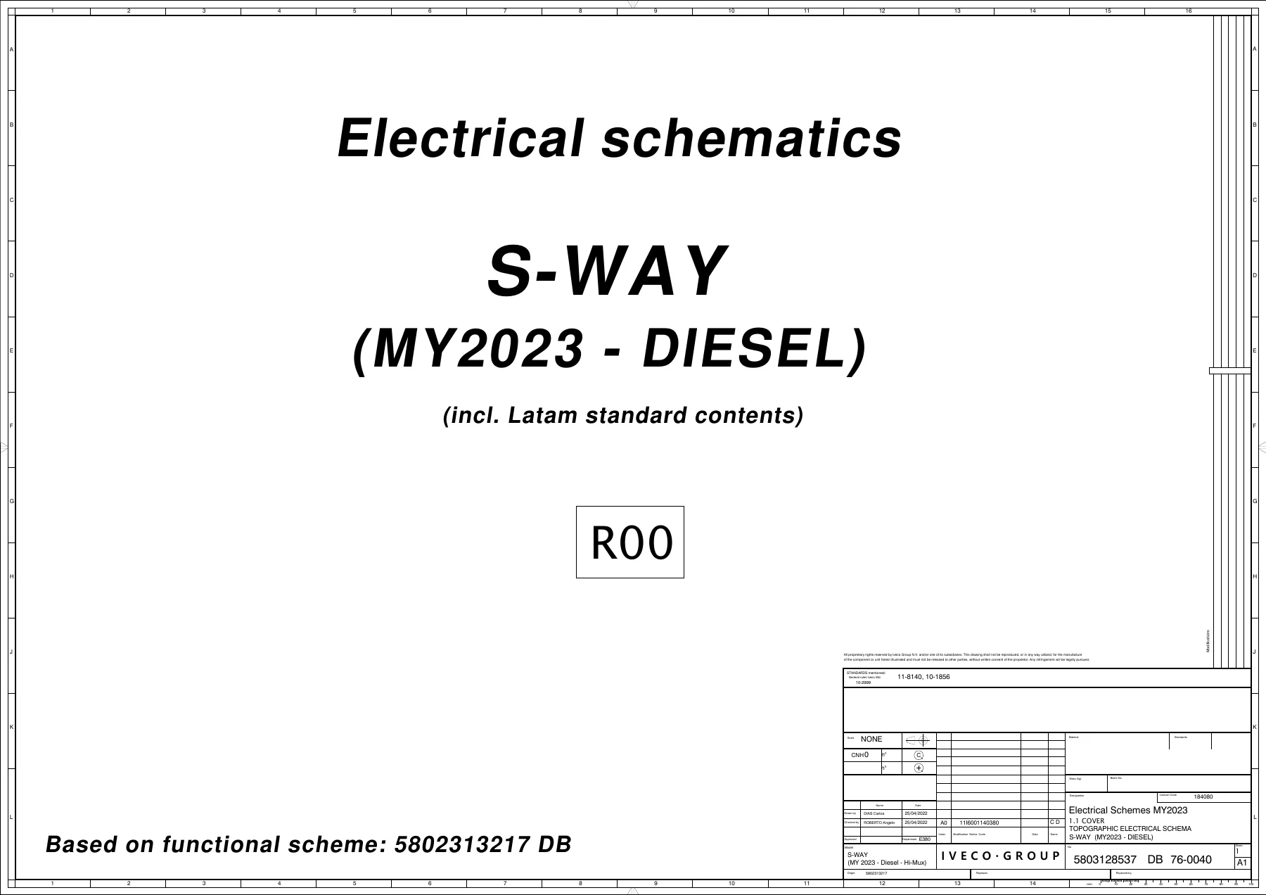
Complete Iveco S-Way MY2023 Diesel Electrical Schematics Manual (R00, doc 5803128537 DB 76-0040). Full topographic wiring diagrams, circuit schematics, fuse layouts, connector pinouts, CAN bus networks, and module contents for the S-Way Diesel with Hi-Mux electrical system.
Description
Iveco S-Way MY2023 Diesel Electrical Schematics Manual
This is the complete Iveco S-Way MY2023 Diesel Electrical Schematics Manual (document 5803128537 DB 76-0040, revision R00), the same topographic electrical schema used by Iveco technicians to trace circuits, diagnose faults, and understand the full electrical architecture of the S-Way truck with Hi-Mux electrical system. Whether you are troubleshooting a no-start condition, repairing damaged harness sections, installing bodybuilder equipment, or performing complex module diagnostics, this Iveco S-Way wiring diagram PDF gives you the complete circuit-level view of the vehicle’s electrical system.
File Details
- Manual type: Topographic Electrical Schematics (Wiring Diagrams)
- Brand: Iveco
- Model: S-Way (MY2023 – Diesel)
- Document number: 5803128537 DB 76-0040
- Revision: R00
- Language: English
- Page count: 126 pages
- File format: PDF
- Standards referenced: 11-8140, 10-1856
Chapters Covered
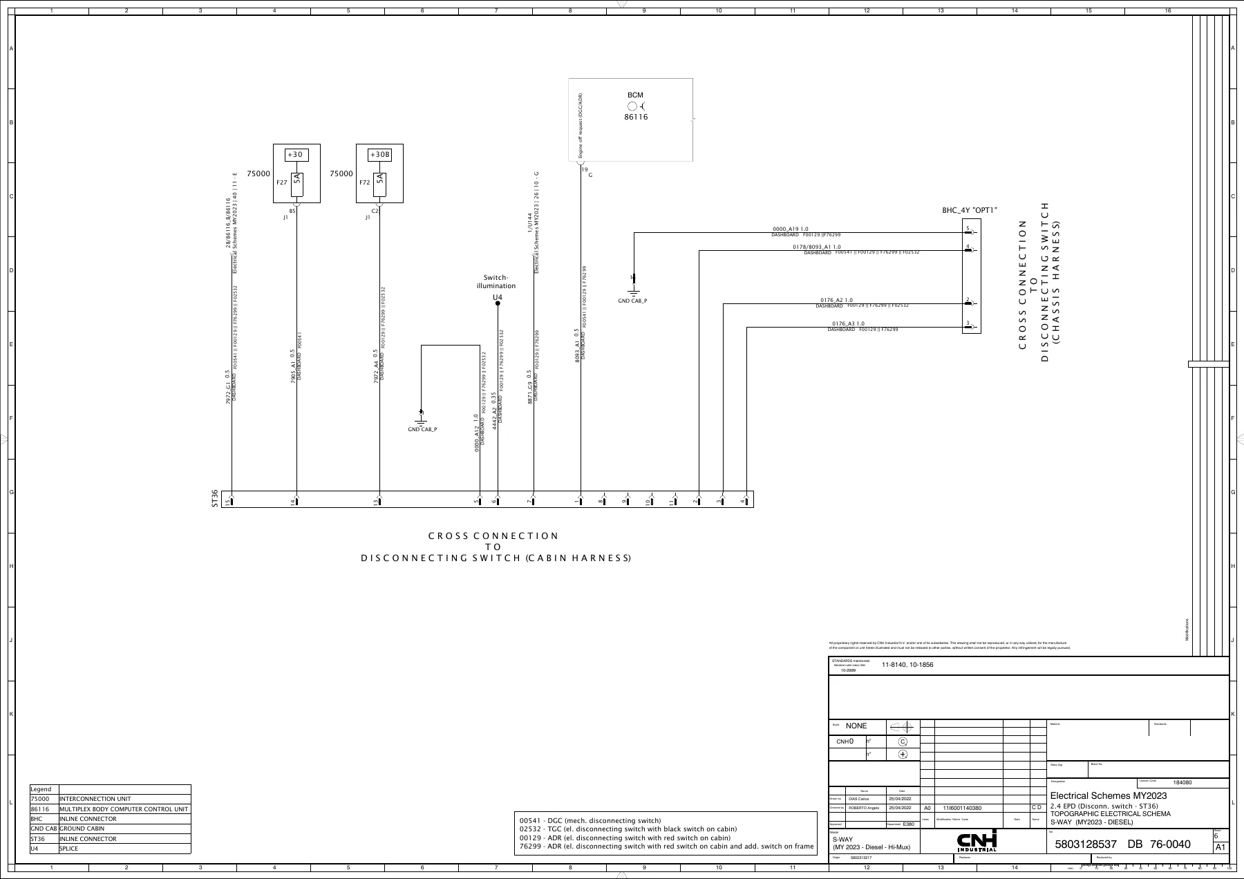
- EPD – Electrical Power Distribution (CFB, K15 Relay, Battery / Charging Socket / IBS, Starter / Alternator, Disconnecting switches)
- EDC – Engine Diesel Control (MD1 – E3/E5/E6)
- VCM – Vehicle Control Module
- OBD-BB – On-Board Diagnostics / Body Builder Connectors
- Steering Column (SWI, CS)
- IC-TACHO – Instrument Cluster / Tachograph
- BCM – Body Control Module
- FCM – Front Control Module
- Brake Systems (EBS3, ABS E8, EABS/ACC)
- Axle Function
- Gearbox (Traxon, Intarder, eHorizon)
- NIS / FMS / P&CM / Radio
- ECAS – Electronically Controlled Air Suspension
- CLIMA – Climate Control
- CAB – Cabin Electrical Systems
- EM – Expansion Module
- TOLL COLLECT
- LDWS – Lane Departure Warning System
- TAIL LIFT
- Adapter Cables
- Connectors / Splices
- CAN BUS Networks
- Bulkhead Connectors
- EPD Contents (Fuse/Relay assignments, module contents)
EPD – Electrical Power Distribution
The EPD chapter covers the complete power distribution architecture of the S-Way, including the CFB (Central Fuse Box), K15 relay circuits, battery and charging socket wiring, IBS (Intelligent Battery Sensor), starter and alternator circuits, and the various disconnecting switch configurations for ST36, CAB, Chassis DGC/TGC, and Chassis ADR. You get full pinout data for the EPD unit, fuse assignments for all +30, +K15, and +30B circuits, and relay module contents across the complexity and variant configurations. This section is essential for diagnosing parasitic draws, tracing power supply faults, and understanding how the vehicle’s electrical loads are protected and distributed.
EDC – Engine Diesel Control
The EDC section provides complete schematics for the MD1 engine management system across E3, E5, and E6 emission configurations. It covers ECU supply, sensor wiring, actuator circuits, and the specific pinout data for the engine control unit. Whether you are diagnosing a sensor fault code or tracing a wiring issue to the engine harness, these diagrams give you the exact connector views and wire routing you need.
VCM – Vehicle Control Module
The VCM chapter details the vehicle control module wiring, including inputs from the accelerator pedal, brake switches, PTO switches, and output signals to the engine ECU and other vehicle systems. It covers the VCM connectors, splices, and the specific circuits for the gearbox interface and Intarder communication. This is critical for understanding how the vehicle’s central control module interacts with driveline and body systems.
OBD, Steering Column, and Instrument Cluster
This group of chapters covers the diagnostic connector (OBD-BB) wiring for both CAB and body builder connectors, the steering column switches (SWI) and clockspring (CS), and the instrument cluster and tachograph (IC-TACHO) circuits. You get pinout data for the OBD connectors, steering wheel switch signals, and the complete wiring for the instrument cluster including speed signal, battery voltage, and ignition feeds. These sections are indispensable when diagnosing driver interface faults, warning lamp issues, or communication problems with diagnostic tools.
BCM – Body Control Module
The BCM chapter is one of the most extensive in this manual, covering all body control functions across 27 sub-sections. It includes internal light switches, supply circuits with polyswitch protection, sensor and switch inputs, cluster switches, bumper wiring, window lifter and door lock circuits, wiper and pump controls, differential lock switches, PTO-N90 switch, horn circuits, mirror heating (LHD), door speakers, additional door components, external light switches, working lights, seat wiring, power supply circuits, Power Packer, rear warning buzzer, beam level, immobase station, and the LIN BUS network. Each sub-section provides connector views, wire colors, and circuit routing for accurate diagnosis and repair of any body electrical fault.
FCM – Front Control Module
The FCM section covers rear lights, APU sensors and pressure switches, rear tank sensors, trailer connectors for both tractor and truck configurations, SML, fuel sensor and tank heater, and differential lock circuits. These diagrams are essential for diagnosing lighting faults, trailer connection issues, and fuel system electrical problems.
Brake Systems
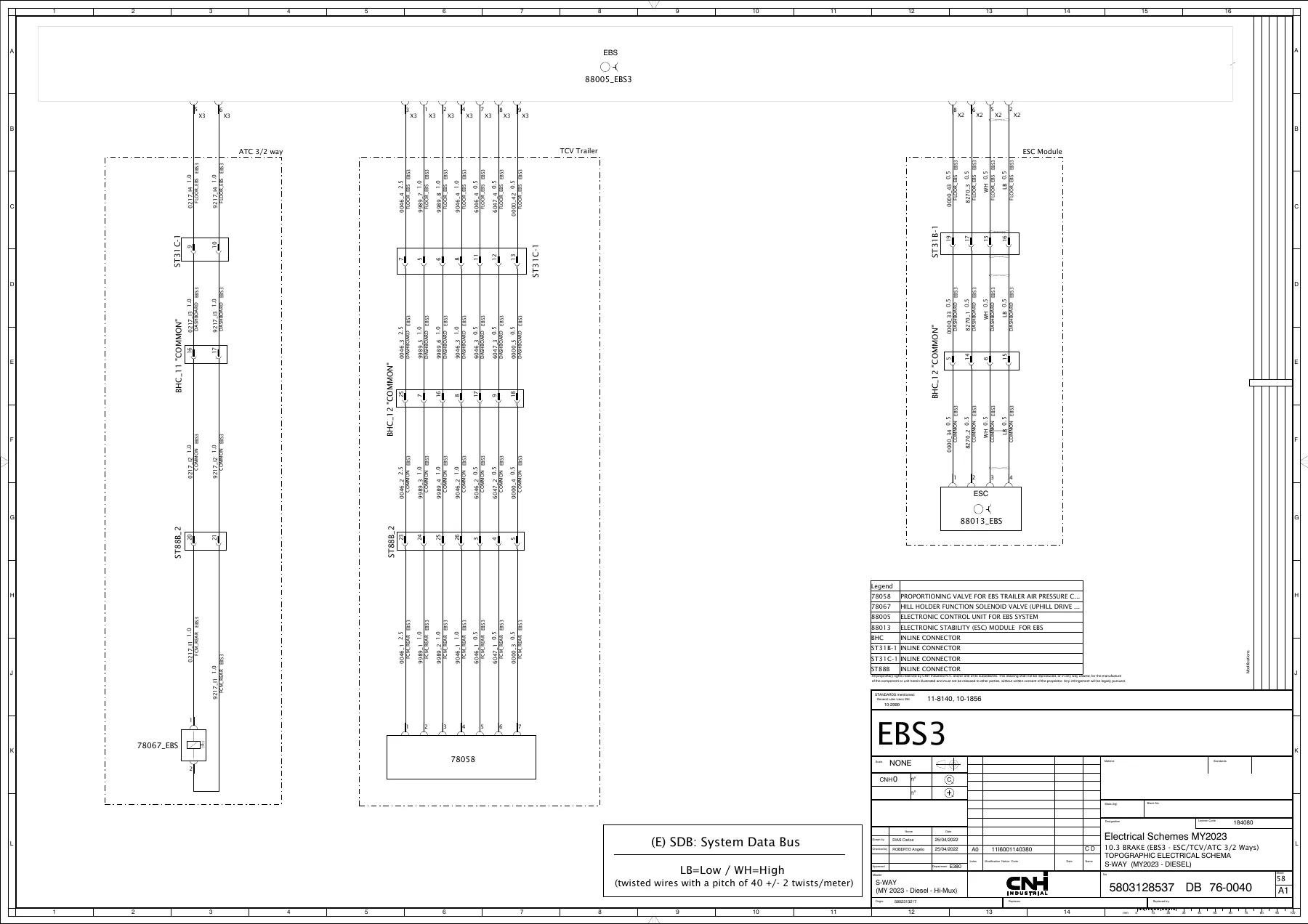
The brake system schematics cover EBS3 and ABS E8 configurations in detail, including supply, sensors, axle modulators, ESC/TVC/ATC 3/2 way valves, pressure sensors, trailer modulator circuits, and EABS/ACC systems. You get full connector pinouts for the EBS ECU, ABS ECU, and all associated sensors and modulators. This is critical for safe diagnosis and repair of the vehicle’s braking and stability control systems.
Gearbox and Axle Functions
The gearbox chapter covers Traxon, Intarder, and eHorizon systems with complete wiring for the gearbox ECU, retarder, and GPS-based predictive cruise control module. The axle function section covers SPUNTO and 3rd axle lifting circuits. These diagrams are essential for driveline diagnostics and repair.
NIS, FMS, P&CM, and Radio Systems
This group covers the NIS (Infotainment System), FMS (Fleet Management System), P&CM (Powertrain and Chassis Management), and radio systems across multiple cab configurations. It includes ST40, ST45, and 12V CB radio wiring, FMS and antenna ground circuits, P&CM connectors, NIS and USB wiring, radio power supplies for both 12V and 24V systems, tweeter wiring, and two antenna overview pages. This is invaluable for diagnosing infotainment, telematics, and communication faults.
ECAS – Electronically Controlled Air Suspension
The ECAS chapter covers cabin and chassis air suspension wiring across multiple configurations (Cabin, Cabin/Chassis, Chassis_1, Chassis_3). It includes sensor wiring, solenoid valve circuits, and ECU pinouts for the air suspension control module. These diagrams are essential for diagnosing ride height, leveling, and suspension fault codes.
CLIMA – Climate Control
The climate control chapter covers ST20/ST21 systems, parking cooler with NTAC, manual AC, and automatic AC configurations. It includes wiring for the climate control panel, blower motor, compressor clutch, sensors, and actuator motors. This section supports diagnosis of heating, ventilation, and air conditioning faults.
CAB and EM – Cabin Electrical Systems
The CAB chapter covers rear cab wiring, DC/DC converter circuits, additional cabin lights, 12V/24V sockets, identification lights, and power USB sockets in the bed zone. The EM (Expansion Module) chapter covers ST48, PTO switches, CAB connections, and chassis connections. These sections support bodybuilder installations and cabin electrical accessory diagnostics.
TOLL COLLECT, LDWS, and TAIL LIFT
This group covers the toll collection system, lane departure warning system, and tail lift circuits for ST32/LCS-LCS configurations. These diagrams support the diagnosis and repair of these specialized vehicle systems.
Adapter Cables, Connectors, and Splices
This section provides comprehensive documentation of adapter cables, all inline connectors and splices with their ST descriptions, connector pinouts, and splice locations. It is an essential reference for harness repair and modification work.
CAN BUS Networks
The CAN BUS chapter covers all vehicle CAN networks including A-BCB-LHD, B-VDB-LHD, F-ECB, K-ECC-LHD (E6 only), G-FMS/SGW, and a complete CAN overview. Each network section shows the topology, terminating resistors, and module connections. This is critical for diagnosing communication faults and understanding the vehicle’s network architecture.
Bulkhead Connectors and EPD Contents
The bulkhead chapter provides complete pinout tables for all bulkhead connectors (1X through 14), including the overview page showing connector locations. The EPD contents section provides the EPD unit contents, module contents by complexity and variant, EPD overview, CFB overview, fuse and relay part numbers, and BCM polyswitch assignments. This reference material is essential for understanding the vehicle’s electrical configuration and ordering correct replacement components.
Why This Iveco S-Way Electrical Schematics Manual Is Essential
Electrical faults on modern commercial vehicles like the Iveco S-Way can be among the most challenging and time-consuming to diagnose. Without accurate wiring diagrams, technicians resort to guesswork, replacing parts unnecessarily, and spending hours tracing circuits manually. This Iveco S-Way MY2023 Diesel Electrical Schematics Manual eliminates that guesswork by providing the complete circuit-level documentation you need to diagnose faults accurately and efficiently.
Whether you are a fleet maintenance technician, independent workshop owner, or bodybuilder installing auxiliary equipment, this manual gives you the exact connector views, wire colors, pin assignments, and circuit routing for every electrical system on the vehicle. From the engine management system to the body control module, from the brake ECU to the infotainment system, every circuit is documented with the precision that professional diagnostics demand.
The manual is particularly valuable for bodybuilder applications, with dedicated sections covering the body builder connectors (OBD-BB), EM expansion module, bulkhead connectors, and adapter cables. If you are installing a tail lift, crane, refrigeration unit, or any other auxiliary equipment, these sections show you exactly where to interface with the vehicle’s electrical system safely and correctly.
For technicians diagnosing complex faults involving multiple modules and networks, the CAN BUS section is indispensable. It shows the complete network topology, including which modules communicate on which bus, where the terminating resistors are located, and how the networks are structured. This makes it possible to diagnose communication faults systematically rather than by trial and error.
The fuse and relay documentation in this manual is equally comprehensive. With complete fuse assignments for +30, +K15, and +30B circuits, relay module contents across all complexity and variant configurations, and part numbers for all fuses, relays, diodes, and polyswitches, you have everything needed to diagnose power supply faults and order correct replacement components.
IMAGES PREVIEW
This Iveco S-Way electrical wiring diagrams PDF is delivered as an instant download after payment. There is no shipping, no waiting for a physical book, and no risk of damage or loss. The PDF format means you can access the manual on any device – laptop, tablet, or smartphone – in the workshop, at the roadside, or in the office. You can print individual pages or entire sections as needed, and you can zoom in on complex schematics for detailed viewing.
If you work on Iveco S-Way trucks, this Iveco S-Way MY2023 Diesel Electrical Schematics Manual is not just a useful reference – it is an essential tool that will pay for itself many times over in accurate diagnostics, efficient repairs, and avoided parts replacement. Download your copy today and have the complete electrical documentation for the S-Way at your fingertips.

Reviews
There are no reviews yet.